Voltage Frequency Controller for Linear,
Non-Linear Load
Prof. N.A.Gore1, Prof. R.S.Gadekar2
1
Electrical Engineering Department, Bhivarabai Sawant COE, Narhe, Pune-411046, Maharastra, INDIA.
2
Electronics & Telecommunication Engineering Department, Bhivarabai Sawant COE,, Narhe, Pune-411046, Maharastra, INDIA.
Abstract: This paper deals with voltage and frequency controller for wind generating system with linear, nonlinear, dynamic load and we will see the result for varying wind speed also. The proposed system is modelled and simulated in MATLAB R2009 using Simulink. The controller that controls both voltage and frequency of an asynchronous generator along with its improvement of power quality. The proposed controller has bidirectional active and reactive power flow capability along with battery energy storage system by which it controls the system voltage and frequency with variation of consumer load. Given system is also beneficial for harmonic elimination as well as load balancing also.
By using the simulation techniques as well as some mathematical modelling we have some results of different loads at different condition in tabular form.
Index Terms: Battery energy storage system, Excitation capacitor, Isolated Asynchronous generator, linear, on linear dynamic load, voltage and frequency controller, wind energy conversion system.
I. INTRODUCTION
Due to rapid increase in the population and standard of living, we are faced with energy crisis. Conventional sources of energy are increasingly depleted. Hence, Non-Conventional Energy Sources have emerged as potential source of energy in India and world at large.
Among the various non-conventional energy sources, wind energy is emerging as the potential major source of energy for growth. The three phase induction machine with a squirrel cage rotor work as three phase induction generator operated in self-excitation power generation mode with an excitation capacitor bank. Induction machine has many advantageous characteristics such as robustness, reliability and low cost. The induction machine may use as motor or generator. Self-excited induction generator (SEIG) is useful for wind power electricity generation in remote Areas, because they do not required any external power supplies to produce excitation magnetic fields [4].The excitation can be provided by a capacitor bank connected to the stator windings of the induction generator.
When three phase induction generator feeds unbalanced, nonlinear or dynamic load system becomes unbalanced or disturbed with some current and voltage harmonics which creates the power losses. This type of problems can be solved by using IGBT based VSC which having capability of harmonics elimination and load balancing.
II. CONFIGURATION OF ISOLATED WIND ENERGY SYSTEM.
As shown in Fig.1.system is isolated from grid which we considered as stand-alone system with three phase asynchronous generator, wind turbine, excitation capacitor linear/nonlinear/dynamic ,balanced/unbalanced load and voltage and frequency controller. With a specified controller which have three phase insulated gate bipolar junction transistor with a battery at its DC link, with some interfacing inductor. The proposed controller is having bidirectional flow capability of active and r e active powers because of which it can control the magnitude and demand. Accordingly the principle of frequency regulation for generating constant frequency at fixed speed, the total generated power should be consumed by the applied load additional generated power might best oredin the revolving component of the
Machine and it increases the machine speed which in turns increases the system frequency. On the other hand when there is variation In wind speed sand corresponding variation in the machine speed, the battery and consumer loads absorb such amount of power by which desired frequency of the generated voltage can be achieved.
In proposed control scheme, the frequency controller isused for extracting active component of the source current. When there is deficiency in the generated power, the battery supplies the additional required load. The battery supplies the additional required load demand through process of discharging and maintains the constant frequency along with providing the functions of load balancing [3] . While there is an excess generated power it starts charging and consumes additional generated power which is not consumed by the consumer load.
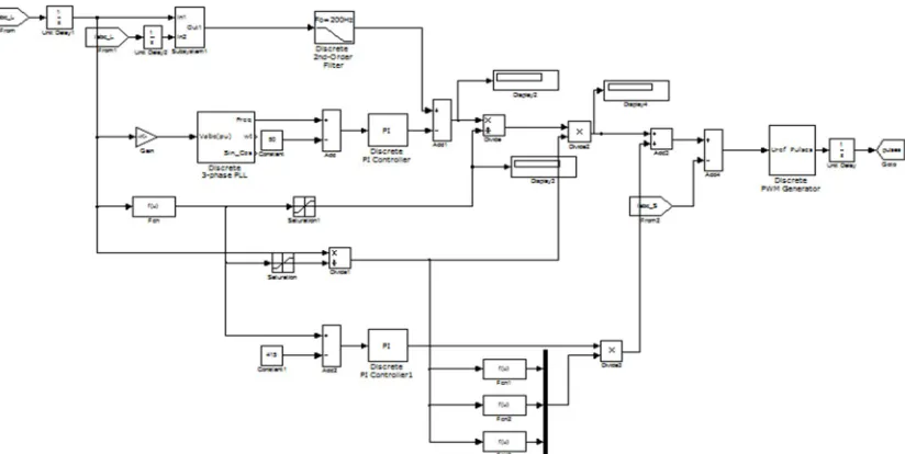
Fig.2.Control strategy for an isolated wind energy conversion system
A. Control Scheme
Given control scheme is totally based on generation of reference source current (irsa,irsb,irsc),.Reference source currents are having two components one is active and other is reactive component. Active component for regulating the frequency of generated voltage and reactive component for regulating the magnitude of generated voltage. The amplitude of active power component of source current is given by dividing the difference of filtered load power and output of PI frequency controller to the amplitude of the terminal voltage.
B. Control Scheme Modelling
Some control scheme equations are given here.
C. Derivation of active component of source current
The active component of reference source current (Idm) Is given by,
Idm = [2(PL filter – Pc)/ 3Vtm] (1)
In above equation(Pc) is output of PI frequency controller which is given by, Pc(n)=Pc(n-1)+Kpf{fer(n)-fer(n-1)}+Kif*fer(n) (2)
Vtmis terminal voltage which is given by, Vtm = {(2/3)(Vla2+ Vlb2+ Vlc2)}1/2 (3)
And finlly PL filter is filtered instantaneous load power .PL is load power (instantaneous active power) with following equation with three phase to two phase transform, PL =( Vα*iα+V β*i β) (4)
Vα= (√2/3)( Vla – 1/2 Vlb-1/2 Vlc) (5)
V β = (√2/3)(√3/2Vlb-√3/2Vlc) (6)
iα= (√2/3)( ila – 1/2 ilb-1/2 ilc) (7)
i β = (√2/3)( √3/2ilb-√3/2ilc) (8)
The instantaneous line voltages at the terminals of an asynchronous generator (Vla,Vlb and Vlc) are considered sinusoidal with their amplitude as Vtm.. The unity amplitude templates are having instantaneous value is given as da = Vla/ Vtm. , db = Vlb/ Vtm , dc = Vlc/ Vtm (9)
Instantaneous values of in phase components of reference source currents are given by irda = Idm* ida , ,irdb = Idm* idb , ,irdc = Idm* idc (10)
D. Derivation of Reactive Component of Reference Source Current. Tha ac voltage error at the nth sampling instant as Ver(n) = Vtmref(n) – Vtm(n (11)
The output of PI controller (Iqm(n)) for maintaining constant ac terminal voltage at the nth sampling instant is given as Iqm(n) = (Iqm(n-1) + Kpa{ Ver(n) - Ver(n-1)+Kia * Ver(n)}) (12)
Where Kpa and Kia are the proportional and integral gain constant of the voltage proportional integral (PI) controller. The instantaneous quadrature component of reference source current are given by, irqa = Iqm* iqa , ,irqb = Iqm* iqb , ,irqc = Iqm* iqc (13)
where qa, qb, qc are the another set of unit vectors having a phase shift of 90deg leading the corresponding unit vectors are derived as ,qa= -db /√3 +dc/ /√3 (14)
qb = √3da/2 +(db-dc)/2√3 (15)
qc=−√3da/2 +(db-dc)/2√3 (16)
E. Computation of Reference Source Current Total reference source current are sum of in phase and quadrature component of the reference source currents as, irsa=irqa+ irda (17)
irsbirqb+ irdb (18)
irsc=irqc+ irdc (19)
F. PWM Signal Generation Reference source currents are compared with sensed sourced current .The current error are computed as, isaerr = irsa – isa (20)
isber = irsb – isb (21)
These current errors are amplified with a gain (K) and the amplified signals are compared with fixed frequency (10 kHz) triangular carrier wave of amplitude to generate gating signals for IGBTs of VSC of the controller.
III. MODELLING OF PROPOSED SCHEME
Modelling of the proposed scheme including asynchronous generator, wind turbine and controller is carried out in MATLAB R2009.
A. Mechanical System
Principle of energy conversion,
Wind mills or turbines works on the principle of converting kinetic energy of the wind in to mechanical energy. The power generated by wind turbine can be generated by,
P = 0.5A ρ CpVw3 (23)
To generate constant frequency the additional generated power with increased wind speed is stored into battery and the speed of the generator is maintained constant [1]. The wind machine is mainly affected by wind speed, area swept by rotor, density of air, rotational speed of machine, and radius of rotor and no of blade.
Tip speed ratio, λ = R Ω / Vw
R = Rotor radius (m), Ω = rotational speed of the rotor (rad/s)
Solidity, σ = blade area / A = (average chord x blade length x number of blades) / A
Cp is coefficient of performance which is calculated as,
Cp = C1{(C2 / λi) – C3β – C4)}e-(C/ λi)+C6 λ (24) Where pitch angle β is 0deg.
B. Modelling Of Electrical System
The electrical system consists of asynchronous generator with excitation capacitor. Capacitor bank is connected in delta to generate the rated voltage at no load while additional demand of reactive power is met by the controller.
C. Modelling Of The Voltage Frequency Controller
The controller consists of current controlled voltage source converter (CC-VSC) with the battery at its DC link. As per the requirement the given battery model is developed. The terminal voltage of the equivalent battery (Vb) is calculated as[5],
Vb> (2√2/√3)VLL (25)
Battery is a energy storage unit, its energy is represented in kWh when a capacitor is used to model the battery model having capacitance (CB).
D. Modelling of The Consumer Load.
Linear, non-linear and dynamic loads are modelled as per the given system. With some resistive, reactive components, with three phase diode rectifier and L-C filter with resistive element.
IV. RESULTS AND ANALYSIS
Here the system performance is described with proper simulation diagram and its simulated results for different load condition and for varying wind speed.
We have some nomenclature for different electrical quantities, generator voltage (Vabc_L), generator current(iabc_S), load current(iabc_L), capacitor current(ia_CC), controller current(iabc_C), terminal voltage(Vtm), frequency (F),wind speed(Vw), battery current(ib), battery voltage(Vb), instantaneous active load power (PL) , filtered load power (PLfilter), speed of dynamic load(ὠm) and load torque(TL).
A. Performance of Controller With Static Load
Fig .3 Matlab Simulation of different types of load.
Fig .4 Matlab Simulation of control strategy.
For nonlinear load at 1.5 sec a three phase nonlinear load is applied and voltage and frequency remain constant with less harmonic distortion. At 1.65 sec one phase is opened then also the controller maintains voltage and frequency remains constant as per fig 6.
B. Performance for Dynamic Load.
Dynamic load performance is shown in fig 7.At 1.5sec direct on line starting of an dynamic load is performed .Due to high starting current a deep discharge of the battery is also observed to regulate the frequency .At 1.75 sec a load torque is applied and then the motor load current is increased but the controller performs and it maintains the magnitude and frequency of generated voltage constant.
V. CONCLUSION
[image:6.612.105.517.315.522.2]Fig.5.Balanced/unbalanced load with fixed wind speed.
Fig.5.Balanced/unbalanced load with fixed wind speed.
Fig.7.waveform for dynamic load with fixed wind speed.
Fig.7.waveform for dynamic load with fixed wind speed.
REFERENCES
[1] B.Singh ,S.S.Murthy and S.Gupta,”A Voltage and frequency controller for self-excited induction generator,”Elect.PowerCompon.Syst.,vol.34,pp.141-157,Feb.200
[2] B.Singh ,S.S.Murthy and S.Gupta,”Analysis and design of electronic load controller for self-excited induction generator,”IEEETrans.Energy Conversion,vol.21,no.1,pp.285-93,Mar.2006
[3] M.Ceraola,”New dynamic models of lead –acid batteries,” IEEE Trans.Power Syst.,vol.15,no.4,pp.1184-1190,Nov.
[4] M.M.Neam,F.F.M.EI-Sousy,M.A.Ghazy,and M.A.Abo-Adma,”The dynamic performance of an isolated self-excited induction generator driven by a variable speed wind turbine,”inProcInt.Conf.Clean Elect . Power(ICCEP’07),May 21-23,2007,pp.536-543.