АВТОМАТИЗОВАНІ
СИСТЕМИ
УПРАВЛІННЯ
НА
ТРАНСПОРТІ
UDC 656.256.3:621.316.91
K. I. YASHCHUK
1*1*Dep. «Automation, Remote Control and Communication», Dnipropetrovsk National University of Railway Transport named after Academician V. Lazaryan, Lazaryan St., 2, Dnipro, Ukraine, 49010, tel. +38 (066) 647 54 89,
e-mail [email protected], ORCID 0000-0002-8606-5790
POTENTIALS RAILWISE PROPAGATION STUDY
Purpose. The article deals with conducting the study of the potentials and currents propagation along the rails to evaluate the potential difference and the current asymmetry in the rails that may have an impact on the work of rail-way automatics and supervisory systems. Methodology. To compass the purpose, the author applies methods of analysis and synthesis of track circuit electrical engineering calculations, mathematical modeling and methods of homogeneous and heterogeneous ladder circuits. Findings. The conducted theoretical studies indicate that in the mountainous sections of DC traction railways there are very high-level currents, whereby even at nominal asymme-try ratio the asymmeasymme-try current will be unacceptably high. The re-equipment of running line with the automatic blocking system with tonal rail circuits resulted in reduction of the number of impedance bonds, the equalizing func-tions of which required further advanced research, that allowed obtaining the potential railwise propagation curves when installing the impedance bonds every 6 and 5 km. The resulting potential difference was too high for railway automation systems, so the potential propagation study was conducted with impedance bonds placed every 3 and 3.5 km, which greatly improved the operation conditions of track circuits. Originality. The proposed method for calculating the propagation of potentials and currents in the rail network of DC traction line is characterized by the representation of the common ladder circuit of each rail as a series of T-shaped four-poles connected in cascade, taking into account the grounding of the contact-line supports on the nearer rail. It has allowed estimating the levels of asymmetry currents that branch into the equipment of track circuits and have a negative impact on their operation.
Practical value. The obtained results can be used in designing and re-equipping the running lines with new railway automatics and supervisory systems, as well as for evaluating the influence of high asymmetry currents on the rail-way automation systems operation.
Keywords:traction currents; track circuits; impedance bond; asymmetry current; potentials propagation
Introduction
Traction current has a significant impact on the operation of automatic block systems (AB) [1]. There are rail sections where it reaches very high levels, resulting in melting of track choke cables. Such are the mountain sections of railways with electric drive of direct current. In this way, the problem of railwise propagation of potentials caused by traction current becomes actual, the study of which will allow to estimate the difference between the derived potentials and the negative impact on the equipment of the track circuits (TC), in particular, the tonal ones (TTC).
Purpose
The purpose of the work is to study the propa-gation of potentials along the rails in order to eval-uate the impact of traction current on TTC opera-tion. This will enable us to take a number of neces-sary technical measures to combat asymmetry, as well as to investigate their effectiveness in ad-vance.
Methodology
ex-plained by the presence of steep climbs, to over-come which the locomotive requires large traction effort, provided by 2-3 electric locomotives. The work examined the mountainous section with DC electric traction of Lavochne – Beskid – Skotar-skoye of Lviv Railways. As a result of the carried out researches it was established that traction cur-rents reach 7000 A on this site and it is expedient to re-equip the section AB with 50 Hz frequency TC onto the ABTK system, which uses TTC with-out isolating joints [2], resulting in reduced number of impedance bonds (IB), as in fact, in the case of TTC, they are installed only for the potential alignment in the rails, while the IBs pass less cur-rent. This greatly facilitates the operation of the track circuits on the running line because the im-pedance bond is a weak point in the TC, especially in the presence of large traction currents [3].
If we take into account such an important pa-rameter as the asymmetry ratio, then its limiting value according to the technical conditions is equal to ka0.12. In this case, the difference in rail currents will be equal to ΔI = 432А. In practice, the asymmetry ratio can reach 0.2. As a result of the high traction currents flow, normal operation of IBs is violated due to their inadmissible heating and magnetization [4]. As a result of thermal over-heating, IB may even break down. The common occurrence is the IB core saturation, resulting in a decrease in the IB input impedance to signal cur-rent, which may lead to the voltage reduction on the track receiver up to the voltage value of non-attraction of relay armature. Consequently, the asymmetry current increase can cause a parametric failure of the TC.
Since the rails are not isolated, part of the re-verse traction current flows through the ground. This fact has a significant impact on a number of phenomena, in particular, the traction network re-sistance and TC operation [5]. The earth leakage current from rails depends on the potential differ-ence between the rails and the ground and the re-sistance of the circuit through which this current flows. The circuit consists of two consecutive parts. The first part is the resistance of the transi-tion point of the current from the rails to the sleep-ers and ballast; the second part is the resistance of the ground itself on the path of leakage current.
For the analysis of the spread of traction current along the rails, regardless of the train situation and
the section complexity, it is necessary to determine the load of the substations [6]. To simplify the cal-culation, we can accept some assumptions that will not make a tangible error. With good insulation of rails from the ground in the absence of earth leak-age, the train loads can be distributed between sub-stations in the usual way – inversely proportional to distances to the neighbouring substations (with constant area of the section of the overhead wires and the same voltage of traction substations). If the transition resistance from the rails to the ground will be minimal, then a significant part of the cur-rent will flow on the ground and, in the distribution of loads between the substations, one can neglect the resistance of the earth return [7] (rails shunted to earth), since it is much less than the resistance of the overhead wires. The latter will mostly deter-mine the current distribution. It can be assumed that wandering currents do not significantly affect the current distribution between substations [8].
Before carrying out the research it is necessary to determine the load of the traction substations [9]. The current of the first substation – I1, the second one – I3, the current of the locomotive –
2
I . The distances from the substation to the loco-motive are known. Then the load of the traction substations (their currents) can be found, based on the distances from the locomotive to each of the substations. Thus, the traction current of the first substation is determined by:
2 1
1 2
2
4 200А
l l I I
l
. Traction current of the
second substation: 1
3 2
2
2 800А
l I I
l
.
Once the load of all substations has been de-termined, we can go to the calculation circuit. In the calculations the following resistances play a great role: rt – resistance of 1 km of track, Ohm·km; rT – transient resistance from rails to earth at a length of 1 km, Ohm/km; re – earth re-sistance.
certain current. The calculation circuit contains one load when the earthing connector is infinitely dis-tant. At the same time, all loads are considered in turn, taking into account the currents of substa-tions.
The basis for analytical study of the distribution of constant voltages and currents along the rail line (RL), which is an electric long line, are differential equations of the Helmholtz type [10]. At the line input there is a source of reverse traction current leakage, herewith the expressions for the distribu-tion of voltage and current along the line have the
form,
0
dU Z I
dx , 0
dI U
dx . Solutions of these
equations lead to the following equations:
2 2
2 0
d U U dx ,
2 2
2 0
d I I
dx , (1)
Where 0 R Y0 0 , (Np km ); – RL propagation coefficient at constant current;
0, 0
R Y – specific rail resistance (Ohm km ) and isolation conductivity (Cm km ) of element of the line x.
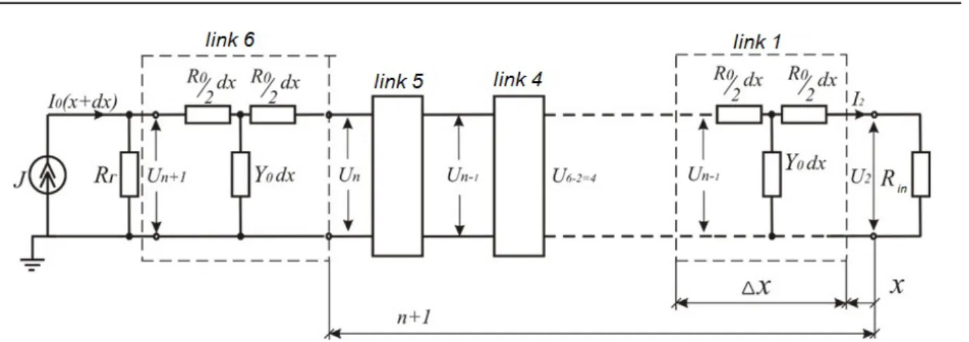
Each track is replaced by two two-wire homo-geneous ladder circuits (HLC) «rail-earth» [11] and is presented by T-shaped four-poles sequen-tially connected in a cascade (Fig. 1). The esti-mated area of the RL can be taken of any length, we conditionally take l=3 km, it will contain N=6 identical segments of the line of 0.5 km (the quan-tization scale can be varied, it is determined by the line simulation accuracy).
If we neglect the resistance of IB to direct current, then both of the HLCs of the line «rail – earth» are shorted, providing alignment of the potentials of both rails with each other.
During circuit design it is taken into account that the parameters of the equivalent network (СЗ EN) of the lines can vary widely, and with the relatively low isolation resistance, the input/output resistance of HLC 1, 2 are equal to characteristic ones. Then, the traction current load of each line at the boundary of the block sections is the resistance of the IB half-coils ( 0.006 Ohm ), indicating the operation of each of these HLC lines in the short-circuit mode (SC).
General solutions for equation (1) can be writ-ten for a symmetric four-pole in x coordinate sys-tem and in A-parameters. We consider the voltage
1
п
U and current I1 at HLC input (x l ) as given. Then the equation of the four-pole for the entire circuit can be written as follows:
2 1 0 c
2 1 1
c
chГ shГ ;
shГ
chГ .
U U N I R N N
I U I N R
(2)
The equations (2) correspond to the equations of symmetrical four-poles in A-parameters, if adopted:
11 12 c
21 22
c
chГ ; shГ ; shГ
; chГ .
A N A R N N
A A N
R
For one link HLC can be recorded
Г Г
1 ; 1 ,
п п п п U I е е U I
Whence Г ln n 1 ln n 1
n n U I U I
– transfer
constant (weakening) of the link (in long lines it is the analogue of l), herewith
, 1 1 n n
U I – voltage and current at the input of 1
n -th link; U In, n – voltage and current at the
input of n-th link; 0 c
0
R R
Y
– characteristic
re-sistance of the line.
Permanent transfer of the entire HLC is charac-terized by the ratio of voltages at the beginning and at the end of the HLC:
1.2 1
1
1.2 2.3 2
c ln (U )(U )...(Un )
Г U U U
,
where Un, Un1 – voltage at the input of the link
Fig. 1. Homogeneous circuit «rail-earth» with T-links
Consequently, the transfer constant Гc Г N. The calculated parameters of the T-shaped circuit «rail-earth» of the HLC-1 track are R0 and Y0. The resistance of the rail loop to direct current is 0.1 Ohm km (with copper rail bonds or steel du-plicated ones) then the resistance of one rail is0.05 Ohm km . Herewith, the resistance of the rail of the (butting) link track consists of two com-ponents. As the practice of operation shows, both of these components are random variables and de-pend on a number of random factors such as ambi-ent temperature, specific resistance of the steel, bond resistance, which depends on the quality of weld, the number of torn wire ropes, etc. The cal-culations adopt the regulatory values of the pa-rameter R0. The rail insulation conductivity Y0 is also a parameter that depends on many random factors: ballast material (crushed stone, sand), type of sleepers and term of their operation, humidity and ambient temperature, foreign impurities clog-ging the ballast section (mineral salts, coal, etc.). The operation experience shows that Y0 can vary from 10 to 0.02 Cm km.
When connecting any types of grounding de-vices to the rails in double rail track circuits, in order to prevent the shunting of the latter, all grounding devices must be connected to one rail line [12]. In the case of connection of grounding devices to the rail with two conductors, the dis-tance between their connections should be minimal and should not exceed 200 mm. The last require-ment is determined by the fact that the continuity fault of the rail line between the conductor connec-tion points is not controlled. The connecconnec-tion of
grounding devices to one rail line of double rail circuits creates a transverse asymmetry of the rail line [13]. Parameters for calculating HLC-2 (of the second rail) are selected taking into account the ground of the contact line supports (3). Conductiv-ity and resistance of general rail ground:
02 0 sp
і sp 32
і sp ,
G = Y Y R R R
R R
(3)
where Y Rsp, sp – conductivity and resistance of the support ground.
At the same time, the conductivity Y0 during the year to a lesser extent depends on the tempera-ture, since the depth of landing in the soil is more than 3 m. In the summer, the conductivity of the supports can reach 0.3–0.4 cm, due to unsatisfac-tory maintenance of the spark gaps IPM-62. Also, the analysis of operating experience and calcula-tions shows that the most unfavourable period of the rail line operation is winter, because then the potentials and currents can reach the highest value.
Consequently, according to the proposed meth-od, each rail is considered separately as an HLC consisting of a certain number of T-shaped four-poles. Output parameters of one of the HLC are selected taking into account the grounding of the contact line supports. The use of the given meth-odology resulted in writing the program in Maple programming environment [14, 15], which allows to obtain the diagrams of the propagation of cur-rents and potentials along the rails.
poten-tial of one pole will be input for the next four-pole. While the greater the number of four-poles, the greater the accuracy of the data received.
The number of four-poles is given in the output data. The received curves of the propagation of currents and potentials along each of the rails give an opportunity to evaluate the asymmetry currents in the rails.
Findings
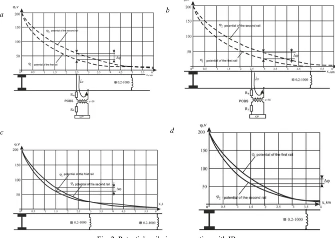
As can be seen from the obtained dependencies (Fig. 2, a, b), the potential levels for each of the rails will be different. Their difference will fall near the IBs, which align the potentials on the rails. It should be noted that the potential difference () in the middle of the section between the IB connection and the train will be maximal [16].
Fig. 2. Potentials railwise propagation with IB:
а – installed every 5 km; b – installed every 6 km; c – installed every 3 km; d – installed every 3,5 km
For example, in Figure 2, a, which shows the potentials railwise propagation with IB installed every 5 km = 34 V. This indicator is quite high, since it will have a negative impact on the opera-tion of RC equipment. When installing IB every 6 km (Fig. 2, b) will be 37 V.
In order to reduce the potential difference, it was proposed to set equalizing IB with a smaller interval. Figures 2, c, d present the curves of poten-tials railwise propagation when IB installed every 3 km and 3.5 km, which show that at a distance of 1.5 km will be maximum and will equal 14 V. This indicator is completely satisfactory for the
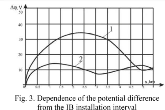
operation of railway automation devices [17]. Figure 3 shows the dependence of the potential difference from the IB installation interval. Curve 1 shows the change in the potential difference with IB installed every 5 km, curve 2 – with IB installed every 3 km. This graph confirms the expediency of the proposed reduction in the IB installation inter-val, because the maximum values between the two curves vary significantly.
а b
Fig. 3. Dependence of the potential difference from the IB installation interval
Originality and practical value
The proposed method for calculating the prop-agation of potentials and currents in the rail net-work of DC traction line is characterized by the representation of the common ladder circuit of each rail as four-poles, taking into account the grounding of the contact-line supports on the near-er rail. It has allowed estimating the levels of asymmetry currents that branch into the RC equipment. The obtained results can be used in designing and re-equipping the running lines with new railway automatics and supervisory systems (RAS), as well as for evaluating the influence of
high asymmetry currents on RAS systems opera-tion.
Conclusions
The study of impact of high levels of traction currents on the equipment of AB systems was car-ried out. The method for calculating the propaga-tion of potentials and currents along the rails for the railway sections with DC electric traction was improved. It consists in the study of propagation of of each individual rail, which is represented as HLC «rail-earth» and presented as a series of T-shaped four-poles connected in cascade, taking into account the grounding of the contact-line sup-ports on the end rail.
The proposed method allowed carrying out the potentials railwise propagation study with IB in-stalled every 6 and 5 km (Fig. 2, a, b). The poten-tial difference was too large for uninterrupted func-tioning of RAS equipment. Therefore, it was pro-posed to shorten the IB installation interval to 3 and 3.5 km [18]. As shown in the received dia-grams and in the resulting comparative graph in Figure 3, the proposed solution is appropriate.
LIST OF REFERENCE LINKS
1. Аркатов, В. С. Рельсовые цепи. Анализ работы и техническое обслуживание / В. С. Аркатов,
Ю. А. Кравцов, Б. М. Степенский. – Москва : Транспорт, 1990. – 295 с.
2. Атабеков, Г. И. Теоретическиеосновыэлектротехники / Г. И. Атабеков. – Москва : Энергия, 1978. – 591 с.
3. Гаврилюк, В. И. Испытанияновыхтипов подвижногосоставанаэлектромагнитнуюсовместимость с устройствамисигнализацииисвязи / В. И. Гаврилюк, В. И. Щека, В. В. Мелешко // Наукатапрогрес транспорту. – 2015. – № 5 (59). – С. 7–15. doi: 10.15802/stp2015/55352.
4. Дыдышко, П. И. Земляноеполотножелезнодорожногопути : справочник / П. И. Дыдышко. – Москва :
Интекст, 2014. – 416 с.
5. Дьяконов, В. П. Maple 10/11/12/13/14 вматематическихрасчетах / В. П. Дьяконов. – Москва : ДМК Пресс, 2014. – 800 с.
6. Каганов, З. Г. Электрическиецеписраспределеннымипараметрамиицепныесхемы / З. Г. Каганов. –
Москва : Энергоатомиздат, 1990. – 247 с.
7. Марквардт, К. Г. Электроснабжение электрифицированных железных дорог : учеб. для вузов ж.-д.
трансп. / К. Г. Марквардт. – 4-еизд., перераб. идоп. – Москва : Транспорт, 1982. – 528 с.
8. Разгонов, А. П. Дослідженняроботирейковихкілтасистемиавтоблокуваннянаперевальнихділянкахз крутимпрофілем / А. П. Разгонов, К. І. Ящук // Вісн. Дніпропетр. нац. ун-ту залізн. трансп. ім. акад.
В. Лазаряна. – Дніпропетровськ, 2011. – Вип. 37. – С. 186–190.
9. Разгонов, А. П. Оцінка впливу асиметрії тягового струму на роботу перегінних рейкових кіл /
А. П. Разгонов, К. І. Ящук // Безпекатаелектромагнітна сумісністьназалізн. трансп. (S&EMC) : тези
VII Міжнар. наук.-практ. конф. / Дніпропетр. нац. ун-тзалізн. трансп. ім. акад. В. Лазаряна. – Дніпро, 2016. – С. 60.
10. Разгонов, А. П. Профилактическоеобслуживаниерельсовыхцепей / А. П. Разгонов. – Москва : Транс
11. Щека, В. І. Дослідженнявпливузворотноготяговогострумунарежимироботитональнихрейковихкіл
/ В. І. Щека, І. О. Романцев, К. І. Ящук // Вісн. Дніпропетр. нац. ун-тузалізн. трансп. ім. акад. В. Лаза
-ряна. – Дніпропетровськ, 2012. – Вип. 42. – С. 24–28.
12. Щека, В. І. Дослідженнямеханізміввпливуконтактноїмережінарейковікола / В. І. Щека // Науката прогрестранспорту. – 2015. – № 3 (57). – С. 27–35. doi: 10.15802/stp2015/46036.
13. Budnik, K. Potential of the electric flow field produced in the earth by stray currents from D.C. traction of complex geometry / K. Budnik, W. Machczyński, J. Szymenderski // Poznan University of Technology Aca-demic Journals. Electrical Engineering. – 2016. – No. 85. – P. 29–40.
14. Gander, W. Scientific Computing: An Introduction using Maple and MATLAB / W. Gander, M. J. Gander, F. Kwok. – Berlin : Springer-Verlag, 2014. – 905 p.
15. Lucca, G. Estimating stray currents interference from DC traction lines on buried pipelines by means a Monte Carlo algorithm / G. Lucca // Electrical Engineering. – 2015. – Vol. 97. – Iss. 4. – P. 277–286. doi:10.1007/s00202-015-0333-6.
16. Mariscotti, A. Distribution of the traction return current in AC and DC electric railway systems / A. Mariscotti // IEEE Transactions on Power Delivery. – 2003. – Vol. 18. – Iss. 4. – P. 1422–1432. doi: 10.1109/tpwrd.2003.817786.
17. Modelling of earthing and return current systems of electric railways / A. Zynovchenko, G. George, S. Körner, A. Stephan // Elektrische Bahnen. – 2014. – No. Spec. 1. – P. 132–136.
18. Verbert, K. Fault diagnosis using spatial and temporal information with application to railway track circuits / K. Verbert, B. De Schutter, R. Babuška // Engineering Applications of Artificial Intelligence. – 2016. – Vol. 56. – P. 200–211. doi: 10.1016/j.engappai.2016.08.016.
К
.
І
.
ЯЩУК
1*1*Каф. «Автоматика, телемеханікатазв’язок», Дніпропетровськийнаціональнийуніверситетзалізничноготранспорту
іменіакадемікаВ. Лазаряна, вул. Лазаряна, 2, Дніпро, Україна, 49010, тел. +38 (066) 647 54 89,
ел. пошта [email protected], ORCID 0000-0002-8606-5790
ДОСЛІДЖЕННЯ
РОЗПОВСЮДЖЕННЯ
ПОТЕНЦІАЛІВ
УЗДОВЖ
РЕЙОК
Мета. Унауковійроботіпередбачаєтьсяпроведеннядослідженнярозповсюдженняпотенціалівтастру
-мівуздовжрейокізметоюоцінкирізниціпотенціалів іструмуасиметріїурейках, якіможутьздійснювати впливна роботу систем залізничної автоматики та телемеханіки. Методика. Длядосягнення поставленої метизастосованіметодианалізутасинтезуелектротехнічнихрозрахунківсхемрейковихкіл, математичного моделювання, методи однорідних та неоднорідних ланцюгових схем. Результати. Проведені теоретичні дослідження свідчать про те, що на гірських ділянках залізниць з електричноютягою постійного струму протікаютьструмидужевисокихрівнів, заякихнавітьприномінальномукоефіцієнтіасиметріїструмаси
-метріїбуденедопустимовеликим. Урезультатіпереобладнанняперегонусистемоюавтоблокуваннязтона
-льнимирейковими колами скоротилася кількість дросель-трансформаторів, вирівнюючи функції яких по
-требувалиподальшогодосконалогодослідження. Булиотриманіепюрирозповсюдженняпотенціалівуздовж рейокпривстановленнівирівнюючихдросель-трансформаторівкожні 6 та 5 км. Отриманірізниціпотенціа
-лів виявилися зависокими для роботи систем залізничної автоматики, тому було проведено дослідження розповсюдження потенціалів при інтервалі розташування дросель-трансформаторів кожні 3 та 3,5 км, що значнопокращилоумовироботирейковихкіл. Науковановизна. Запропонованийметодрозрахункурозпо
-всюдженняпотенціалівтаструмівурейковіймережіперегонуелектричноїтягипостійногострумувідрізня
-ється представленням загальної цепної схеми кожної рейки у вигляді послідовно з’єднаних в каскад
Т-подібнихчотириполюсниківізурахуваннямзаземленняопорконтактноїмережінаближнюрейку. Цедо
-зволилооцінитирівніструмівасиметрії, яківідгалужуютьсявапаратурурейковихкілта здійснюютьнега
-тивнийвпливна їхроботу. Практичназначимість. Отримані результатиможуть використовуватися при проектуваннітапереобладнанніперегонівновимисистемамизалізничноїавтоматикитателемеханіки, ата
-кождляоцінкивпливувисокихструмівасиметріїнароботусистемзалізничноїавтоматики.
Е
.
И
.
ЯЩУК
1*1*Каф. «Автоматика, телемеханикаисвязь», Днепропетровскийнациональныйуниверситетжелезнодорожноготранс
-портаимениакадемикаВ. Лазаряна, ул. Лазаряна, 2, Днипро, Украина, 49010, тел. +38 (066) 647 54 89,
эл. почта [email protected], ORCID 0000-0002-8606-5790
ИССЛЕДОВАНИЕ
РАСПРОСТРАНЕНИЯ
ПОТЕНЦИАЛОВ
ВДОЛЬ
РЕЛЬСОВ
Цель. Внаучнойработепредполагаетсяпроведениеисследованияраспространенияпотенциаловитоков вдольрельсовсцельюоценкиразностипотенциаловитокаасимметрииврельсах, которыемогутоказывать влияние на работу систем железнодорожной автоматики и телемеханики. Методика. Для достижения
поставленнойцелипримененыметодыанализаисинтезаэлектротехническихрасчетовсхемрельсовых це
-пей, математического моделирования, методы однородных и неоднородных цепных схем.
Результаты. Проведенныетеоретическиеисследованиясвидетельствуютотом, чтонагорныхучасткахже
-лезныхдорогсэлектрическойтягойпостоянноготокапротекаюттокиоченьвысокихуровней, прикоторых даже при номинальном коэффициенте асимметрии ток асимметрии будет недопустимо большим.
Врезультате переоборудования перегона системойавтоблокировки стональнымирельсовыми цепями со
-кратилоськоличестводроссель-трансформаторов, выравнивающиефункциикоторыхтребовалидальнейше
-годосконального исследования. Были получены эпюры распространения потенциалов вдоль рельсов при установкеуравнивающих дроссель-трансформаторовкаждые 6 и 5 км. Полученныеразности потенциалов оказались слишкомвысокими для работы системжелезнодорожной автоматики, поэтому было проведено исследование распространенияпотенциалов приинтервалерасположения дроссель-трансформаторовкаж
-дые 3 и 3,5 км, чтозначительноулучшилоусловияработырельсовыхцепей. Научнаяновизна. Предложен
-ныйметодрасчетараспространенияпотенциаловитоковврельсовойсетиперегонаэлектрическойтягипо
-стоянного тока отличаетсяпредставлением общей цепной схемыкаждого рельса в виде последовательно соединенныхвкаскадТ-образныхчетырехполюсниковсучетомзаземленияопорконтактнойсетинаближ
-нийрельс. Этопозволилооценитьуровнитоковасимметрии, которыеответвляютсяваппаратурурельсовых цепейиоказываютнегативноевлияниенаихработу. Практическаязначимость.Полученныерезультаты могут использоваться припроектировании и переоборудовании перегонов новыми системами железнодо
-рожнойавтоматикиителемеханики, атакжедляоценкивлияниявысокихтоковасимметриинаработусис
-темжелезнодорожнойавтоматики.
Ключевыеслова:тяговыетоки; рельсовые цепи; дроссель-трансформатор; ток асимметрии; распростра
-нениепотенциалов
REFERENCES
1. Arkatov, V. S., Kravtsov, Y. A., & Stepenskiy, B. M. (1990). Relsovyye tsepi. Analiz raboty i tekhnicheskoye obsluzhivaniye. Moscow: Transport.
2. Atabekov, G. I. (1978). Teoreticheskiye osnovy elektrotekhniki. Moscow: Energiya.
3. Havrilyuk, V. I., Shcheka, V. I., & Meleshko, V. V. (2015). Testing new types of rolling stock for electromag-netic compatibility with signaling and communication devices. Science and Transport Progress, 5 (59), 7-15. doi:10.15802/stp2015/55352
4. Dydyshko, P. I. (2014). Zemlyanoye polotno zheleznodorozhnogo puti [Manual]. Moscow: Intekst. 5. Dyakonov, V. P. (2014). Maple 10/11/12/13/14 v matematicheskikh raschetakh. Moscow: DMK Press.
6. Kaganov, Z. G. (1990). Elektricheskiye tsepi s raspredelennymi parametrami i tsepnyye skhemy. Moscow: Energoatomizdat.
7. Markvardt, K. G. (1982). Elektrosnabzheniye elektrifitsirovannykh zheleznykh dorog [Guide]. Moscow: Transport.
10. Razgonov, A. P. (1980). Profilakticheskoye obsluzhivaniye relsovykh tsepey. Moscow: Transport.
11. Sсheka, V. I., Romancev, I. O., & Jasсhuk, E. I. (2012). The investigation of reverse traction current influence on tone track circuit modes. Bulletin of Dnipropetrovsk National University of Railway Transport, 42, 24-28. 12. Shcheka, V. I. (2015). Impact mechanisms research in the contact network on rail track circuits. Science and
Transport Progress, 3 (57), 27-35. doi:10.15802/stp2015/46036
13. Budnik, K., Machczyński, W., & Szymenderski, J. (2016). Potential of the electric flow field produced in the earth by stray currents from D.C. traction of complex geometry. Poznan University of Technology Academic Journals Electrical Engineering, 85, 29-40.
14. Gander, W., Gander, M. J., & Kwok, F. (2014). Scientific Computing: An Introduction using Maple and MATLAB. Berlin: Springer-Verlag.
15. Lucca, G. (2015). Estimating stray currents interference from DC traction lines on buried pipelines by means a Monte Carlo algorithm. Electrical Engineering, 97 (4), 277-286. doi:10.1007/s00202-015-0333-6
16. Mariscotti, A. (2003). Distribution of the traction return current in AC and DC electric railway systems. IEEE Transactions on Power Delivery, 18 (4), 1422-1432. doi:10.1109/tpwrd.2003.817786
17. Zynovchenko, A., George, G., Körner, S., & Stephan, A. (2014). Modelling of earthing and return current sys-tems of electric railways. Elektrische Bahnen, Special 1, 132-136.
18. Verbert, K., De Schutter, B., & Babuška, R. (2016). Fault diagnosis using spatial and temporal information with application to railway track circuits. Engineering Applications of Artificial Intelligence, 56, 200-211. doi:10.1016/j.engappai.2016.08.016
Prof. A. P. Razghonov, D. Sc. (Tech.), (Ukraine); Prof. O. I. Stasiuk, D. Sc. (Tech.), (Ukraine) recommended this article to be published