TECHNICAL UNIVERSITY OF CLUJ-NAPOCA
ACTA TECHNICA NAPOCENSIS
Series: Applied Mathematics, Mechanics, and Engineering Vol. 60, Issue III, September, 2017
COMPARATIVE STUDY ON THE DYNAMIC AXLE LOADS AND ON THE
DYNAMIC WHEELS LOADS OF DIFFERENT CLASSES CARS
Nicolae CORDOŞ, Adrian TODORUŢ, Mihai-Dan BURDEA, Monica BĂLCĂU
Abstract: Determination of the dynamic axle loads and wheels loads of the passenger cars is necessary due
to their influences on the gripping forces, the conditions at which the stability of the car can be lost, as well at the design stage of the passenger cars, with influence on the braking system, on the axles, but also on their suspension. By comparing the dynamic loads on different classes of the passenger cars, it aims to highlight the parameters which influence the dynamic loads and parameters that influence the maximum grip force.
The study of the paper includes: the choice of three different classes of passenger cars and one representative passenger cars for each class considered, in order to determine their dynamic loads; performing the experimental measurements on the determination of the static normal loads on the wheels/axles of the three cars under consideration in order to determine the position of the center of gravity for each of them; the development of numerical modeling to result in dynamic loads, the maximum grip force and the dynamic coefficients for the three passenger cars in different operating situations (starting, braking and in cornering) and for different natures and conditions of the road, respectively different longitudinal and transverse inclination of the road, as well as the comparison of the obtained results with the emphasis of the parameters that have an influence on them. The results are interpreted graphics, enabling a comparative study of them.
Key words: passenger car, driving axle, dynamic load, numerical modeling, cornering
1. INTRODUCTION
The static loads of the car axles/wheels are influenced by their static weight distribution on axles/wheels, the position of the center of gravity, and the longitudinal or transverse inclination of the road.
The dynamic loads of the vehicle axles/wheels are given by redistributing their static loads when they are in motion. The redistribution of the static loads on the axles/ wheels of the moving vehicles occurs due to the additional forces and moments that arise during their movement, resulting in the dynamic loads of the car axles/wheels.
Aspects regarding the influences of the dynamic loads of the vehicle axles/wheels on their dynamics are addressed in the literature [1, 2, 3, 4, 6, 7, 8], in which are highlighted the factors of influence on the redistribution of the normal static load on axles/wheels, when the
vehicles are in moving, respectively, the influence of normal reactions on the axles/wheels of the vehicles on the grip forces and on the braking forces or on their stability.
The driving conditions of the vehicle, their design parameters, the geometry, the nature and condition of the road, but also various travel modes (start-up, braking, cornering performance), etc., are [1, 2, 3, 6, 7, 8] the main factors of influence on the dynamic loads of motor vehicle ales/wheels.
normal reaction of the road to the axle/wheel cars during their movement.
During the vehicle start-up, regardless of the position of the driving axle, the coefficient of dynamic change on the front axle will have a sub-unit value, and at the rear axle it will have a supra-unit value, which means that the front axle will disengage dynamically, while the rear axle will dynamically load [1, 2, 3, 6, 7, 8]. Because of this, the cars with both driving axles or rear driving axle will have greater grip force than the cars with front driving axle because the grip force is given by the grip coefficient and the dynamic load of the driving axle.
During the vehicle braking, the front axle will load dynamically while the rear axle will unload dynamically, therefore the coefficient of dynamic change of the front axle will be overunit and at the rear axle will be subunit [1, 2, 3, 6, 7, 8].
In the case of the cars in cornering, the outside wheels of the curve will load dynamically, while the wheels inside the curve will unload dynamically [1, 2, 3, 6, 7, 8].
Certain features of vehicle classes, depending on the technical data and endowments of different car brands of different classes are caught in [5].
2. EXPERIMENTAL MEASUREMENTS
In order to develop a calculation model that would allow the determination of the dynamic loads of the cars and the comparison of the results for different classes of cars, the data obtained from experimental measurements should be used for three cars of different classes
(VW Polo - small class, Ford Focus II - compact class, VW Passat - medium class).
The dynamic loads of the car axles/wheels are influenced by the longitudinal and transverse inclination of the road, as well as by the vehicle's constructive parameters such as weight, wheelbase, track width, longitudinal transverse and height coordinates of the center of gravity. Their study takes into account these infuence parameters.
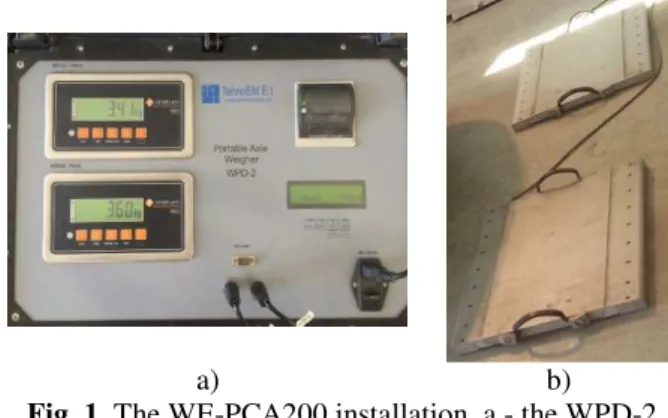
The measurements for determining the weights on the cars axle/wheels were carried
with WE-PCA200 road axle weighing equipment (Figure 1) from the Romanian Automotive Register (Salaj).
a) b)
Fig. 1. The WE-PCA200 installation, a - the WPD-2 summation indicator; B - weighing platforms. We have chosen the WE-PCA200 because it allows the measurement of each static load on each wheel. Thus, weighing the front and rear axles, in addition to the weight of the whole deck, will result the weight on each wheel, so we can calculate the position of the center of gravity not only in the longitudinal plane but also in the transverse plane.
The WPD-2 summation indicator contains two mass indicators, each of which has two measuring ranges: the first range up to 1000 kg with a weighing division of 1 kg and a second range from 1000 kg to 10000 kg with the division of weighing by 5 kg.
The load is displayed for each wheel and the amount of wheel load on axle indicates the load on that axle.
The dimensional parameters of the passenger cars under study were taken from [10, 11] their technical data (Table 1).
Table 1 Technical specifications
of the considered passenger cars Passenger cars
Parameter
VW Polo
Ford Focus
VW Passat
Total length, [m] 3.715 4.472 4.703 Total width, [m] 1.655 1.840 1.746 Total height, [m] 1.420 1.501 1.462 Wheelbase, [m] 2.400 2.640 2.703 Front track width, [m] 1.351 1.535 1.515 Rear track width, [m] 1.384 1.531 1.515
Tire size 175/65
R 13
195/65 R 15
The measurements consisted of weighing the passenger cars to find the static loads on each wheel/axle and the own mass of the passenger cars.
The measurements were made at a constant tire pressure of 0.22 MPa for each of the passenger cars under study. The results obtained from the measurements are shown in Table 2.
Table 2
Results on the normal static load distribution on wheels and axles Passenger
car
Front axle weight, [kg] Rear axle weight, [kg] Total weight, [kg]
Left Right Total Left Right Total
VW Polo 360 341 701 219 203 422 1123
Ford Focus 434 436 870 310 299 609 1479
Vw Passat 512 492 1004 284 286 570 1574
3. NOTATIONS USED IN THE NUMERIC CALCULATION MODEL
The numerical computational algorithm, developed in the MathCAD software, takes into account the constructive parameters of the passenger cars, different displacement regimes of the passenger cars (starting, braking, cornering), geometry, nature and state of the road, etc. and is based on the results of the normal static load distribution on the wheels and on the axles, experimentally obtained in the situation without additional load of the cars (see Table 2). The connection between the external environment and the system is achieved through the use of system parameters that characterize their input/output relationship [9].
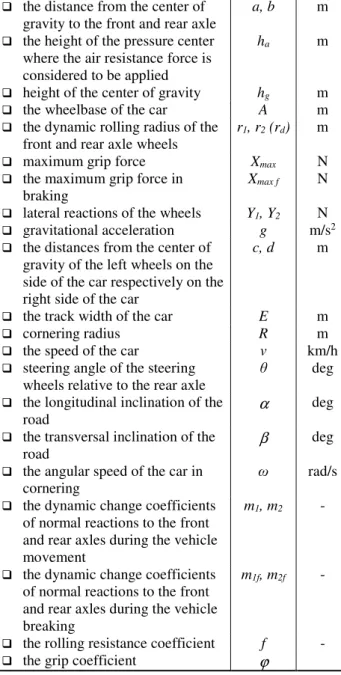
Thus, the main notations used are found in Table 3 [6].
Table 3 The main notations used in the calculation algorithm
Parameter Notation U.M.
tangential reactions at the front and rear axles
X1, X2 N
normal reactions at the front and rear axles
Z1, Z2 N
the sum of dynamic reactions to the left wheels of the car and to the right wheels of the car
Zs, Zd N
air resistance force Fa N
start-up resistance force Fd N
the weight of the car Ga N
the static loads of the axle, when the car is stopped on the
horizontally road
G1, G2 N
the distance from the center of gravity to the front and rear axle
a, b m
the height of the pressure center where the air resistance force is considered to be applied
ha m
height of the center of gravity hg m
the wheelbase of the car A m the dynamic rolling radius of the
front and rear axle wheels
r1, r2 (rd) m
maximum grip force Xmax N
the maximum grip force in braking
Xmax f N
lateral reactions of the wheels Y1, Y2 N
gravitational acceleration g m/s2
the distances from the center of gravity of the left wheels on the side of the car respectively on the right side of the car
c, d m
the track width of the car E m
cornering radius R m
the speed of the car v km/h
steering angle of the steering wheels relative to the rear axle
θ deg
the longitudinal inclination of the road
α deg
the transversal inclination of the road
β deg
the angular speed of the car in cornering
ω rad/s the dynamic change coefficients
of normal reactions to the front and rear axles during the vehicle movement
m1, m2 -
the dynamic change coefficients of normal reactions to the front and rear axles during the vehicle breaking
m1f, m2f -
4. THE METHOD OF NUMERICAL EVALUATION
4.1. Assessment of the center of gravity position for the passenger cars and their
dynamic radius
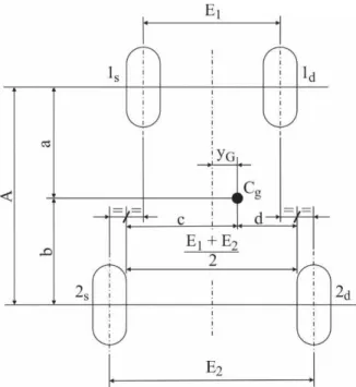
Based on the obtained results by weighing, the calculation model allows the determination of the center of gravity position for each passenger car (Figure 2) [4], depending on the weight distribution on their wheels.
The symbols used in Figure 2 refer to: A - the wheelbase; a, b - the distances from the center of gravity to the front axle (1) respectively to the rear axle (2); c, d - the distances from the center of gravity to the longitudinal planes of the left (s) respectively of the right (d); E1 - front track;
E2 - rear track; yG - distance from the
longitudinal plane of symmetry to the center of gravity; Cg - center of gravity.
Fig. 2. Coordinates of the center of gravity.
The obtained results with respect to the position of the center of gravity are shown in Table 4.
The dynamic radius were determined taking into account tire size, inflation pressure and tire deformation coefficient (λ = 0.93364) [4, 7, 8], obtaining the results shown in Table 5.
The height of the passenger cars center of gravity was determined taking into account the case of unladen cars, the ratio hg/A is
0.160...0.260 [4, 7, 8].
Table 4 Coordinates of the center of gravity for the
considered passenger cars
Passenger cars
Coordinates of the weight center, [m] In the
longitudinal plane
In the transversal
plane
a b c d
VW Polo 0.902 1.498 0.662 0.705 Ford Focus 1.087 1.553 0.762 0.771 Vw Passat 0.979 1.724 0.749 0.766
Table 5 Dynamic radius of the passenger cars
Passenger car Dynamic radius, [m]
VW Polo 0.260346
Ford Focus 0.296197 Vw Passat 0.296197
4.2. Evaluation of the dynamic axle loads of the passenger cars on the longitudinal plane
Taking into account that the cars under study are organized with the driving front axle, the numerical calculation model for determining the longitudinal dynamic loads is developed for this situation as well as for the passenger cars with both braked axles. Also,it is considered [6] that the rolling radius of the wheels are the same for all, and also the rolling resistance coefficient and the grip are the same for all wheels.
Taking into account of the weight of the cars and of their center of gravity positions, is determined the dynamic reactions, the maximum grip force and the dynamic change coefficients for different longitudinal inclination of the road (α = 0°, 3°, 6°), and for its various natures and conditions of the road (asphalt or concrete road in good condition, earth road, snowy road) [6].
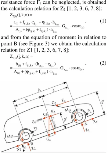
Considering the dynamic model (Figure 3) from the equation of moment in relation to point A and considering that the height of the center of gravity hg is approximately equal to the height of
the pressure center ha and that at the speed at
resistance force Fa can be neglected, is obtained
the calculation relation for Z2 [1, 2, 3, 6, 7, 8]:
) n ( a g ) k , j ( ) k , j ( ) i ( g ) k , j ( d ) k , j ( ) i ( ) i ( 2 cos G h ) f ( A h r f a ) n , k , j ( Z ) i ( ) i ( ) i ( ) i ( α ⋅ ⋅ ⋅ + ϕ + ⋅ ϕ + ⋅ + = =
, (1)
and from the equation of moment in relation to point B (see Figure 3) we obtain the calculation relation for Z1 [1, 2, 3, 6, 7, 8]:
) n ( a g ) k , j ( ) k , j ( ) i ( d g ) k , j ( ) i ( ) i ( 1 cos G h ) f ( A ) r h ( f b ) n , k , j ( Z ) i ( ) i ( ) i ( ) i ( α ⋅ ⋅ ⋅ + ϕ + − ⋅ + = =
. (2)
Fig. 3. The scheme of the forces, moments and reactions that act on a moving passenger car.
In Figure 3, with Mr1 and Mr2 were noted the
moment of the rolling resistance for the front and rear axle, the rest of the sizes being found in Table 3.
Because the cars are provided with front driven axle, the maximum grip force will be [1, 2, 3, 6, 7, 8]:
) n , k , j ( Z ) n , k , j (
Xmax(i) =ϕ(j,k)⋅ 1(i) . (3)
In the developed calculation model, the variable (i) takes values from 1 to 3 and refers to the classes respectively to the cars under study (1 - small class, VW Polo, 2 - compact class, Ford Focus II; 3 - medium class, VW Passat), and the significance of the three variables (j, k, n) is [6]: 1 to 3 and refers to the three natures and conditions of the road (1 - good road or asphalt road, 2 - earth road, 3 - snowy road) and k take values from 0 to 20 and refers to the number of values in which is divided the interval between the minimum and maximum for a certain nature and the condition of the road and n takes values
from 1 to 3 and it refers to the three longitudinal inclination of the road (0°; 3°; 6°).
For each of the cars under consideration, for each operating situation considered, the coefficients of dynamic change of normal responses to the front and rear axles are given by the ratio between the normal dynamic reaction and the static load of one axle [1, 2, 3, 6, 7, 8]:
) i ( ) i ( a ) i ( 1 1 ) i ( 1 ) i ( 1 b A G ) n , k , j ( Z G ) n , k , j ( Z ) n , k , j ( m ) i ( ) i ( ⋅ == =
, (4)
) i ( ) i ( a ) i ( 2 2 ) i ( 2 ) i ( 2 a A G ) n , k , j ( Z G ) n , k , j ( Z ) n , k , j ( m ) i ( ) i ( ⋅ = = =
. (5)
The results on the variation of the dynamic responses, maximum grip force, and the dynamic change coefficients according to the nature and geometry of the road for the passenger cars under study are shown in Figures 4, 5 and 6.
Figure 4 shows that with the the increase of the grip coefficient, regardless of the nature and condition of the road, in the case of the starting vehicle, the dynamic load of the front axle decreases while the dynamic load of the rear axle will increase for all three cars under study. It can also be noticed that the dynamic loads of the cars are directly influenced by the dimensions of the passenger cars as well as by their static loads.
Fig. 4. Variation of the dynamic loads depending on the nature of the road in the case of the considered passenger
cars. 4000 5000 6000 7000 8000 9000 10000
0.1 0.2 0.3 0.4 0.5 0.6 0.7 0.8
D y n am ic l oa d, [ N ]
The grip coefficient, φ
Fig. 5. Variation of the maximum grip force depending on the nature of the road in the case of the considered
passenger cars.
The results in Figure 5 show that with the increase of the grip coefficient, the maximum grip force for each car will increase. It can also be observed that the grip force is influenced by the dynamic load of the car, so the maximum grip force will be higher for the car that has the highest dynamic load on the driving axle. In this case, the medium class car, followed by the compact class car, and the lowest grip force of the car will have the small class car.
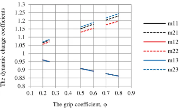
Fig. 6. Variation of dynamic change coefficients depending on the nature of the road in the case of the
considered passenger cars.
The results shown in Figure 6 show that the value of the dynamic change coefficient for the front axle is subunit, and the dynamic change coefficient for the rear axle is superunit, which means that at the vehicle start-up, with increasing the grip, the front axle will have a more dynamic unloaded while the rear axle will have a stronger dynamic load. It can be seen that the coefficient of dynamic change of the front axle is approximately equal for all three cars.
The influence of the coefficient of adhesion on the loads, respectively the dynamic unloaded of the considered car axles, can be seen in Figures 7, 8 and 9. Thus, from the obtained results in the case of a horizontal road, there is a dynamic unload of the front axle and a dynamic load of the rear axle, for all considered cars (Figure 7, the road asphalt or concrete in good condition, Figure 8, earth road, Figure 9, snow-covered road).
Fig. 7. Unloading/loading of the front/rear axle, φ = 0.75.
Fig. 8. Unloading/loading of the front/rear axle, φ = 0.55. From the results shown in Figures 7, 8 and 9, it can be seen that the front axle is unloaded dynamically as against the static loading, by about 13%, in the case of asphalt or concrete road in good condition (see Figure 7), with about 10% in the case of an earth road (see Figure 8) and about with 4% in the case of a snow-covered road (see Figure 9), and the rear axle will dynamically load as against the static load, with approximately 20% for asphalt or concrete road
1000 2000 3000 4000 5000 6000 7000
0.1 0.2 0.3 0.4 0.5 0.6 0.7 0.8 0.9
T
h
e
m
ax
im
um
g
ri
p
for
ce
,
[N
]
The grip coefficient, φ
Xmax1
Xmax2
Xmax3
0.8 0.85 0.9 0.95 1 1.05 1.1 1.15 1.2 1.25 1.3
0.1 0.2 0.3 0.4 0.5 0.6 0.7 0.8 0.9
T
h
e
dy
n
am
ic
c
h
an
g
e
coe
ff
ic
ie
nt
s
The grip coefficient, φ
m11
m21
m12
m22
m13
m23
-25 -15 -5 5 15 25
VW Polo Ford Focus VW Passat
Unloading/loading of the front/rear axle, [%]
Unloading of the front axle, [%] Loading of the front axle, [%]
-20 -10 0 10 20
VW Polo Ford Focus VW Passat
Unloading/loading of the front/rear axle, [%]
in good condition (see Figure 7), with about 15% in the case of an earth road (see Figure 8) and about 8% in the case of a road covered with snow (see Figure 9).
Fig. 9. Unloading/loading of the front/rear axle, φ=0.225.
4.3. Evaluation of the dynamic loads of the passenger car axles in the braking situation
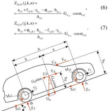
The dynamic reactions in this case are determined from the equations of moments as against to points A and B (Figure 10) [1, 2, 3, 6, 7, 8]: ) n ( a ) i ( g ) k , j ( d ) k , j ( ) i ( f ) i ( 2 cos G A h r f a ) n , k , j ( Z ) i ( ) i ( ) i ( α ⋅ ⋅ ⋅ ϕ − ⋅ + = =
, (6)
) n ( a ) i ( d ) k , j ( g ) k , j ( ) i ( f ) i ( 1 cos G A r f h b ) n , k , j ( Z ) i ( ) i ( ) i ( α ⋅ ⋅ ⋅ − ⋅ ϕ + = =
. (7)
Fig. 10. The scheme of the forces, the moments and the reaction that occur on the vehicle with two axles during
the breaking process.
In the case of braking, the coefficients of dynamic change of the normal reactions to the car axles are given by the relations [6, 7, 8]:
) i ( 1 f ) i ( 1 f ) i ( 1 G ) n , k , j ( Z ) n , k , j (
m = , (8)
) i ( 2 f ) i ( 2 f ) i ( 2 G ) n , k , j ( Z ) n , k , j (
m = . (9)
The maximum grip force in braking will be [1, 2, 3, 6, 7, 8]:
(
Z (j,k,n) Z (j,k,n))
) n , k , j ( X f ) i ( 2 f ) i ( 1 ) k , j ( f ) i max( + ⋅ ϕ = = . (10)Also in this case, the calculation relations are written in the form Z1 (i) f (j, k, n), where f refers
to the brakes, the rest are the same meanings as in the relations (1) and (2).
In the situation of the vehicle braking, results regarding to the variation of the dynamic reactions, maximum grip force and the dynamic change coefficients depending on the nature and geometry of the road are shown in Figures 11, 12 and 13.
Fig. 11. Variation of the dynamic loads of the car axles, in the case of braking, depending on the nature and
condition of the road, on horizontal road.
Fig. 12. Variation of maximum grip force, in the case of braking, depending on the nature and condition of the
road, on horizontal road.
-10 -5 0 5 10
VW Polo Ford Focus VW Passat
Unloading/loading of the front/rear axle, [%]
Unloading of the front axle, [%] Loading of the front axle, [%]
0 2000 4000 6000 8000 10000 12000 14000
0.1 0.2 0.3 0.4 0.5 0.6 0.7 0.8 0.9
D y n am ic l oa d, [ N ]
The grip coefficient, φ
Z11f Z21f Z12f Z22f Z13f Z23f 1000 3000 5000 7000 9000 11000 13000
0.1 0.2 0.3 0.4 0.5 0.6 0.7 0.8 0.9
T h e m ax im um g ri p for ce , [N ]
The grip coefficient, φ
Xmax1f
Xmax2f
Fig. 13. Variation of the dynamic change factors, in the case of braking, depending on the nature of the road, in
the case of the considered passenger cars. For each vehicle braked on both axles, with the increase of the grip coefficient, the dynamic load on the front axle also increases, while the dynamic rear axle load decreases (see Figure 11) and the maximum grip force increases with the increase the grip coefficient (see Figure 12). The maximum grip force is influenced by the weight of the car, so for the three cars under study, the maximum grip force will be higher for the car with the higher dynamic load. Thus, the average class car will have the highest grip force, followed by the compact class car, and the lowest grip force of the car will have the small car. In such situations, the value of the dynamic change coefficient of the front axle is superunit, and the dynamic change coefficient at the rear axle is subunit (see Figure 13), which means that during the braking, the front axle will load dynamically in time and the rear axle will unload dynamically.
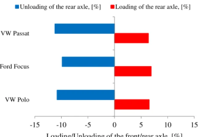
The influence of the grip coefficient on the unloading respectively on the dynamic loads of the brakes of the braked cars can be seen in Figures 14, 15 and 16. Thus, from the obtained results, on the horizontal road, there is a dynamic load at the front axle and a dynamic unload at the rear axle for all considered cars (Figure 7, asphalt or concrete road in good condition, Figure 8, earth road, Figure 9, snow-covered road).
From the results shown in Figures 14, 15 and 16, it can be seen that during the braking, the front axle is dynamically loaded as against to the static load with about 25% in the case of a good asphalt or concrete road (see Figure 14), with approximately 16% in the case of an earth road
(see Figure 15) and about 7% in the case of a snow-covered road (see Figure 16), and the rear axle will be dynamically unloaded from the static load, with about 40% for an asphalt or concrete road in good condition (see Figure 14), about 30% for an earth road (see Figure 15) and about 12% for a road covered with snow (see Figure 16).
Fig. 14. Unloading/loading of the front/rear axle, φ=0.75.
Fig. 15. Unloading/loading of the front/rear axle, φ=0.55.
Fig. 16. Unloading/loading of the front/rear axle,
φ=0.225.
0.5 0.6 0.7 0.8 0.9 1 1.1 1.2 1.3 1.4
0.1 0.2 0.3 0.4 0.5 0.6 0.7 0.8 0.9
T
h
e
dy
n
am
ic
c
h
an
g
e
coe
ff
ic
ie
nt
s
The grip coefficient, φ
m11f
m21f
m12f
m22f
m13f
m23f
-50 -30 -10 10 30 50
VW Polo Ford Focus VW Passat
Loading/Unloading of the front/rear axle, [%]
Unloading of the rear axle, [%] Loading of the rear axle, [%]
-35 -25 -15 -5 5 15 25 35
VW Polo Ford Focus VW Passat
Loading/Unloading of the front/rear axle, [%]
Unloading of the rear axle, [%] Loading of the rear axle, [%]
-15 -10 -5 0 5 10 15
VW Polo Ford Focus VW Passat
Loading/Unloading of the front/rear axle, [%]
4.4. Evaluation of the dynamic load of the cars whees on transversal plane on inclined road and in cornering
Determination of the dynamic reactions in the transverse plane is made when the vehicle is traveling on a transverse inclination road, while executing a turn to the right. The forces and the moments that acting in cornering are shown in Figure 17 [2, 4, 6, 8].
Fig. 17. The forces and the moments that act on the car in cornering.
The notations in Figure 17 refer to: Cg - center
of gravity; Fiy - the force of transversal inertia;
Fix - the force of longitudinal inertia; Miz - yaw
moment resistance; Y1 and Y2 - lateral wheel
reactions; R - turning radius; θ - the steering angle of the steering wheels relative to the rear axle; ω - the angular speed in cornering.
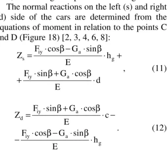
The normal reactions on the left (s) and right (d) side of the cars are determined from the equations of moment in relation to the points C and D (Figure 18) [2, 3, 4, 6, 8]:
d E
cos G sin F
h E
sin G cos F Z
a iy
g a
iy s
⋅ β ⋅ + β ⋅ +
+ ⋅ β ⋅ − β ⋅ =
, (11)
g a
iy
a iy
d
h E
sin G cos F
c E
cos G sin F Z
⋅ β ⋅ − β ⋅ −
− ⋅ β ⋅ + β ⋅ =
. (12)
in which, for v = ct. and R = ct., the inertia force Fiy, is given by the relation [4, 6]:
R g
v G F
2 a iy
⋅ ⋅
= . (13)
Fig. 18. The forces and the moments that act on the cornering car on a road with transversal inclination.
In the calculation model, the calculation relations are written in the form of Zs(i)(hv,lr,nt),
in which s signifies the left wheel reaction, (i) refers to the class of the considered cars and the variables (hv, lr, nt) have the following specifications: hv values from 1 to 6 and refers to the speed of the car, 1 - the speed of 50 km/h, and 6 - the speed of 100 km/h, the speed increasing from 10 to 10 km/h; lr have values from 1 to 5 and refers to the radius of the curve which increases from 100 to 500 m from 100 in 100 m and nt have value from 1 to 3 and refers to the transverse angle b of the road; 1 - corresponds to the angle of 0°, 2 - for β = 3°, and 3 - for β = 6° [6].
Figure 19 shows the variations of the dynamic load on the left and on the right wheels of the cars, depending on their travel speed, on right cornering with curve radius of 500 m, and with no transverse inclination of the road, from which it can be seen that the dynamic loads of the left wheels for all three cars will increase with the increase of the driving speed, while the dynamic unloaded of the right wheels becomes more pronounced.
travel speed of 50 km/h, from which it can be seen that for a constant speed, with the increase of the curve radius, the redistribution of the static normal load is no longer so pronounced.
Fig. 19. The variation of the dynamic loading depending on the vehicle speed, in the case of a 500 m radius of
curve.
Fig. 20. The variation of the dynamic load depending on the radius of the curve at a travel speed of 50 km/h.
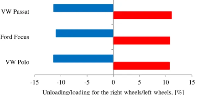
The dynamic load on the left and on the right wheel for the three considered cars are presented as a percentage for a speed of 100 km/h on a constant curve radius of 200 m, with no transverse inclination of the road (Figure 21) and for a 6° transverse inclination angle (Figure 22). If the radius of the curve becomes 500 m and the speed remains 100 km/h, the dynamic load of the left wheels, respectively the dynamic unloaded wheel to the right, are shown as percentage in Figure 23 for the 0° inclination angle of the road and in Figure 24 for the 6° transverse inclination angle, where it can be seen that the left wheels will be dynamically loaded (approximately 11% in the case of a non-transverse tilt road and
4…5% in the case of a 6° transverse inclination) while the right wheel will dynamically unload (approximately 13% for a non-transverse inclination of the road and with 3…5% for a 6° transverse inclination).
Fig. 21. Unloading/loading of the right/left wheels in cornering, β = 0°, v = 100 km/h, and R = 200 m.
Fig. 22. Unloading/loading of the right/left wheels in cornering, β = 6°, v = 100 km/h, and R = 200 m.
Fig. 23. Unloading/loading of the right/left wheels in cornering, β = 0°, v = 100 km/h, and R = 500 m.
4000 5000 6000 7000 8000 9000
40 60 80 100
D
y
n
am
ic
l
oa
d,
[
N
]
Speed, [km/h]
Zs1
Zd1
Zs2
Zd2
Zs3
Zd3
4000 5000 6000 7000 8000 9000 10000
0 100 200 300 400 500 600
D
y
n
am
ic
l
oa
d,
[
N
]
Curve radius, [m]
Zs1
Zd1
Zs2
Zd2
Zs3
Zd3
-35 -30 -25 -20 -15 -10 -5 0 5 10 15 20 25 30 35
VW Polo Ford Focus VW Passat
Unloading/loading for the right wheels/left wheels, [%]
Unloading of the right wheels, [%] Loading of the left wheels, [%]
-25 -20 -15 -10 -5 0 5 10 15 20 25
VW Polo Ford Focus VW Passat
Unloading/loading for the right wheels/left wheels, [%]
Unloading of the right wheels, [%] Loading of the left wheels, [%]
-15 -10 -5 0 5 10 15
VW Polo Ford Focus VW Passat
Unloading/loading for the right wheels/left wheels, [%]
Fig. 24. Unloading/loading of the right/left wheels in cornering, β = 6°, v = 100 km/h, and R = 500 m.
5. CONCLUSIONS
The dynamic loads of the car axles/wheels are influenced by their constructive parameters, which differ from one class of cars to another, as well as the nature and condition of the road, its longitudinal or transverse inclination, and the position and number of driving axles or the mode of operation of the passenger cars (starting, braking or cornering).
The dimensional difference for the passenger cars under study influences the dynamic loads of their axles/wheels, both in the case of the movement on longitudinal, transient regime, uniform motion accelerated or decelerated, as well as in the situation of the cars movement on the road with transversal inclination.
The dynamic change coefficients of the reactions have about the same values, indifferent of the class of the car.
For any type of car in any class, the maximum grip force is influenced by the nature and condition of the road, the static load of the car, and the position and the number of driving axles. The calculation model is developed so that it can be applied to various other types of vehicles that are in a uniform accelerated motion on the longitudinally inclined road, uphill or downhill, in transient regime or braking on both axles, taking into account the different natures and road conditions, different loading cases, and various angles of longitudinal inclination, allowing for graphical results.
Among the possibilities for the continuation of these studies, we can mention:
− extension of the theoretical research in order to evaluate all the influence parameters for determination the operating limit conditions for each class of cars;
− performing the computer simulations to determine the dynamic loads of the axles/wheels for different classes cars, in different operating situations;
− expanding the experimental research to confirm the correctness of the obtained results by analytical and by computer simulation.
6. REFERENCES
[1] Andreescu, C., Dinamica autovehiculelor
pe roţi. Vol.1. Bucureşti, Editura Politehnica Press, 2010.
[2] Macarie, T.N., Automobile. Dinamica. Piteşti, Editura Universităţii din Piteşti, 2003.
[3] Tabacu, Şt.; ş.a., Dinamica autovehiculelor.
Îndrumar de proiectare. Piteşti, Editura Universităţii din Piteşti, 2004.
[4] Todoruţ, A., Bazele dinamicii
autovehicu-lelor. Algoritmi de calcul, teste, aplicaţii. Cluj-Napoca, Editura Sincron, 2005. [5] Todoruţ, I.-A.; Barabás, I.; Burnete, N.,
Siguranţa autovehiculelor şi securitatea în
transporturi rutiere. Cluj-Napoca, Editura U.T.PRESS, 2012.
[6] Todoruţ, A.; Cordoş, N.; Burdea, M.-D.; Bălcău, Monica, The evaluation of normal
load redistribution on the static axles and on the wheels, when the vehicle is in motion. Cluj-Napoca, Buletinul Ştiinţific al UTC-N,
Acta Technica Napocensis, Series: Applied
Mathematics, Mechanics, and Engineering,
Vol. 58, Issue III, September, 2015, pg. 349-360, Editura U.T.PRESS, ISSN
1221-5872,
http://www.atna-mam.utcluj.ro/index.php/Acta/article/view/ 695.
[7] Untaru, M.; ş.a., Dinamica autovehiculelor
pe roți. Bucureşti, Editura Didactică şi Pedagogică, 1981.
[8] Untaru, M.; ş.a., Dinamica autovehiculelor. Braşov, Universitatea Transilvania din Braşov, sectorul Reprografie U02, 1988.
-5 -3 -1 1 3 5
VW Polo Ford Focus VW Passat
Unloading/loading for the right wheels/left wheels, [%]
[9] Varga, B. O., & Iclodean, C. Advanced
research methods of hybrid electric vehicles' performances. Cluj-Napoca, Acta Electrotehnica Journal, Volume 56, Number 1-2, 2015, pg. 111-116, ISSN 2344–5637, https://ie.utcluj.ro/files/acta/2015/Number1 -2/paper19_Varga.pdf.
[10]*** Cars specifications, http://carsspecifications.com, (accesat la 10/05/2017).
[11]*** Technical specifications and fuel
economy of cars, https://autodata24.com/, (accesat la 10/05/2017).
STUDIU COMPARATIV ASUPRA ÎNCĂRCĂRILOR DINAMICE ALE PUNȚILOR ŞI ROȚILOR AUTOTURISMELOR DIN CLASE DIFERITE
Rezumat: Determinarea încărcărilor dinamice ale punților şi roților autoturismelor este necesară datorită influențelor pe care acestea le au asupra forțelor de aderență, asupra condițiilor limită la care stabilitatea autoturismului se poate pierde, precum şi în etapa de proiectare a autoturismelor, având influență asupra sistemului de frânare, a punților, dar şi a suspensiei acestora. Prin compararea încărcărilor dinamice pe diferite clase de autoturisme, se urmăreşte punerea în evidență a parametrilor care au influență asupra încărcărilor dinamice, precum şi a parametrilor care au influență asupra forței maxime de aderență.
Studiul abordat în cadrul lucrării presupune: alegerea a trei clase diferite de autoturisme precum şi câte un autoturism reprezentativ pentru fiecare clasă considerată, în vederea determinării încărcărilor dinamice ale acestora; efectuarea unor măsurători experimentale cu privire la determinarea sarcinilor normale statice pe roţile/punţile celor trei autoturisme luate în studiu, în vederea determinării poziției centrului de greutate pentru fiecare dintre acestea; dezvoltarea unei modelări numerice prin care să rezulte încărcările dinamice, forța maximă de aderențăşi coeficienții de schimbare dinamică pentru cele trei autoturisme în diferite situații de exploatare (demaraj, frânare şi în viraj), şi pentru diferite naturi şi stări ale drumului, respectiv diferite înclinări longitudinale şi transversale ale drumului, precum şi compararea rezultatelor obținute cu punerea în evidență a parametrilor care au influență asupra acestora. Rezultatele obținute sunt cu interpretare grafică, oferind posibilitatea unui studiu comparativ al acestora.
Nicolae CORDOŞ, PhD. Eng., Lecturer, Technical University of Cluj-Napoca, Faculty of
Mechanical Engineering, Department of Automotive Engineering and Transports, Romania, [email protected], Office Phone 0264 202 790.
Adrian TODORUŢ, PhD. Eng., Associate Professor, Technical University of Cluj-Napoca, Faculty
of Mechanical Engineering, Department of Automotive Engineering and Transports, Romania, [email protected], Office Phone 0264 401 674.
Mihai-Dan BURDEA, Eng., Automotive Engineering - Road Vehicles, & Vehicle and Environment,
Front-end Developer at Xoomworks Development RO, [email protected].
Monica BĂLCĂU, PhD. Eng., Lecturer, Technical University of Cluj-Napoca, Faculty of