Left Atrial Appendage Printing Procedure
A Senior Project
Presented to
The Faculty of the Biomedical Engineering Department
California Polytechnic State University - San Luis Obispo
In Partial Fulfillment
Of the Requirements for the Degree
Bachelor of Science
By
Mia von Knorring, Areli Reyes, Brandon Mukai
March, 2020
Table of Contents
Executive Summary 2
Statement of Work 3
Network Diagram 9
Indications for Use 10
Budget 10
Customer Requirements 11
Specification Development 11
Total Available Market 13
Competitive Advantage 14
Intellectual Property Assessment 14
Conjoint Analysis 16
Morphology 18
Concept Evaluation (Pugh Chart) 19
Conceptual Model 19
Detailed Design 25
Prototype Manufacturing Plans 27
Bill of Materials 40
Final Manufacturing Process Instructions 40
Operation Manual 41
Training Guide 41
Test Protocols 41
Testing Data and Analysis 44
Conclusion 49
Discussion 49
Appendix: 51
Executive Summary
The left atrial appendage senior design team aims to assist in closing off the left atrial appendage that is susceptible to coagulation due to non-valvular atrial fibrillation. Coagulation in the left atrial appendage (LAA) can be life threatening as it can lead to a stroke. Dr. Chris Porterfield performs a procedure that uses the Boston Scientific Watchman to close the appendage. He finds that sizing the Watchman properly is difficult with limited visuals from live CT scans. He proposed converting the CT scans into a 3D printed model of the left atrial appendage and left atrium so he can visually measure the opening and predict the trajectory angle of the Watchman device into the left atrial appendage. He currently has a base algorithm and procedure to convert and modify the CT scan into a .stl file, which can then be printed with standard PLA material using a 3D printer on Cal Poly’s campus. The project is limited to the printers and their material capabilities on Cal Poly’s campus. There are currently many programs that convert CT scans to printable files and this project aims to evaluate each to conclude which produces the most accurate 3D model. The procedure to create the model must also be quick to perform, repeatable and reproducible as well as easy to follow.
After researching the various programs, we concluded that 3D Slicer allows us to print
anatomically accurate models of the left atrium and LAA. Using this software, the user uploads CT scans obtained from the radiologist as a DICOM file. Once uploaded, the user will proceed to setting the threshold parameter to the designated values. The user will then scroll through the CT scan to identify the left atrium and LAA in one of the views. After locating the anatomies, the user will use the scissors tool to extrude out any unnecessary anatomy. Once isolated, the model will need to be hollowed out and set to the defined parameters. After a final cut is made to open the model for internal viewing, is it saved as a .stl file and sent to a 3D printing software such as Cura. From this point on, the user will refer to the printer’s manual for the printing procedure while using the parameters we listed as a guide. After the print is concluded, the user will be able to measure the opening of the LAA and determine which entry angle is most optimal.
The key customer requirements we aimed to achieve were ease of use, time, production cost, shape/accuracy, repeatability and reproducibility. For ease of use, we had users go through our MPI, Training Guide and Operations Manual and had them rate between 1-10 on how clear and concise our directions were. We scaled the range so that 1 meant that our procedure was clear and concise enough to replicate while 10 meant it was near impossible to follow. We aimed to achieve an average score of less than 3. For time, we were given a timeframe of 24 hour to fully slice and print the model. Since this procedure is not officially ICD-9 billable yet, the cost of production must remain below $50 per print. Based on the sizing chart provided by Boston Scientific for the various sizes of the Watchman device, we decided that the shape/accuracy must be less than 10% variation from the CT scan, while the repeatability and reproducibility must have no statistical difference in variation from the ANOVA.
After running ANOVA on the data obtained from measuring the 9 testing prints, the results showed that our slicing/printing procedure and the measurements taken for testing were adequate enough to prove the functionality of all our protocols. The results of ANOVA showed that there were no
Training Guide, and Operations Manual and performed the feedback survey we provided. Based on those results, we concluded that our protocols are functional and easy to follow which is essential to producing an accurate model. To prove model accuracy, we had Dr. Porterfield size the Watchman device as he currently does and confirmed that our printed models were accurate.
Statement of Work
Introduction:
Only 100 doctors across the country are trained to perform the Watchman left atrial appendage closure procedure. This preventative, catheter based surgery plugs off the left atrial appendage, preventing debris from traveling upstream and causing strokes. Strokes are the number one cause of disability in the United States and people with atrial fibrillation are more likely to have one due to irregular heartbeat. While the procedure is standardized and doesn’t produce a lot of complications, doctors find picking the right size of Watchman to implant difficult. The left atrial appendage project aims to create a 3D printed model of the left atrial appendage and left atrium for cardiac physiologists to use to aid in sizing and placing the Watchman device during left atrial appendage closure procedures. Dr. Chris Porterfield in San Luis Obispo along with doctors across the nation could use this procedure and model to visualize what size Watchman to select and what angle the catheter must take for placement. The goal of this project is to create an easy to follow procedure to convert a CT scan of the left atrial appendage and left atrium into a 3D printed model. The model should accurately model patient anatomy and provide a quality resolution for physicians to evaluate the system. The Statement of Work outlines the background on this procedure, the design specifications the team aims to follow and a table of steps and timeline for the project.
Background:
The Watchman procedure is a one time procedure that places a permanent closure in the left atrial appendage in order to prevent pooling of blood in the left atrial appendage, later forming a clot. The Watchman comes in five sizes: 21, 24, 27. 30, and 33 mm to better accommodate varying appendage sizes and shapes. Dr. Porterfield has faced challenges while implanting the Watchman in the left atrial
appendage due to limited pre-operative planning opportunities; currently he is limited to the 2D display of computed tomography (CT) scans. The minimally invasive nature of this procedure heavily relies on these scans because during the procedure therefore the user still does not receive a clear view of the anatomical structure. The 2D CT scan does not embody each individual’s left atrial appendage’s spatial geometry and relationship with the left atrium’s anatomical structures. This restricts the user’s ability to determine the angle required to puncture the atrial septum to adequately place the Watchman in the appendage.
Current Tools
Table 1: Current Software
Name Features
SegD - Manual segmentation - Automated segmentation - Set parameters with python
ImageJ-Fiji - Download contains all the ImageJ plugins needed for CT scan segmentation
- Free
3D Slicer - Made specifically for medical imaging - Plug-in capabilities for adding algorithms - Works with all organs
- Bidirectional interface for devices
ITK-Snap - Manual segmentation in 3 orthogonal planes at once - Files supported: NIfTI and DICOM
- Supports time variant images
InVesalius - Can export to STL, OBJ, and PLY files
- Contains volume and surface area measurement - Manual segmentation
- Semi-automatic segmentation
Patents
After reviewing current segmentation software, we researched patents and their claims that our group needs to avoid infringing while designing our process. The following table displays a summary
of 5 patents that pertain to the algorithms and methods used in segmentation and file conversion foranatomical feature printing.
Table 2: CT/MRI scan to 3D printing patents
Patent Number Date Patent Holder
1 10,409,235 May 12, 2016 Siemens Healthcare GmbH
2 10,417,804 July 8, 2019 TeraRecon, Inc.
3 10,438,357 June 16, 2016 Samsung Electronics Co., Ltd.
4 10,417,768 Jan 31, 2019 Shenzhen United Imaging Healthcare CO., LTD
5 10,438,351 June 20, 2019 International Business Machines Corporation
alters the 3D model. A possible claim to infringe is Claim 12, our team can use a 3D printer that has two extruders, one with a water-soluble material such as PVA to act as a base material to be able to print the model in the anatomical orientation of the patient. Patent 2 contains a method to manipulate 2D medical images to produce 3D images in augmented reality. A possible claim of this patent to infringe is Claim 15, our team can keep the medical image data in DICOM format through the first rendered medical image, won’t convert the file to STL or any other file not compatible with DICOM until all segmentation and meshing is completed. Patent 3’s claim three describes image segmentation processes that include determining the boundaries of the medical image by manually adding boundaries. Our group can instead determine anatomical model boundaries through pixel density in the image. In a peer reviewed article we mention in our Statement of Work, we read that heart muscle and surrounding tissue will have different pixel density, so this can be our group’s approach of distinguishing between our target anatomical body and the noise surrounding it. Patent 4’s 8th claim bases segmentation about the sagittal plane, our team can avoid infringing this claim by segmenting about the transverse or coronal plane. Patent 5’s owners use an electronic processor to determine the amount of anatomical structures represented in a medical image. The electronic processor then accesses a knowledge base to depict the photograph of each structure. In order to not infringe on this patent, we will be avoiding this process as well.
Research
The following provides relative information about the segmenting and 3D printing of CT and MRI scans. These journal articles aid in our understanding of the process and development of ideas.
3D printing is being applied to medical imaging for many different reasons. Models are being created for medical education, training, simulation and pre-operative planning. 3D printing in the medical imaging franchise has strong potential that can catalyze innovation in anatomical modeling. There are many opportunities to explore the relationship between medical imaging data and creating 3D models. These opportunities include: establishing an efficient method for image processing workflows to create accurate image segmentations, the usage of 3D printed models as phantoms for medical radiation and imaging studies, and education on what 3D models can do for interpretation of medical imaging. The intended use of the anatomical model will conclude the appropriate requirements for the model such as realism and touch, and these requirements will determine what material should be used for the printed model. Material capabilities in the current market include transparency, printing in different colors, tissue-like characteristics, and dissolvable support material. [1]
3D printing in congenital heart disease (CHD) procedures has been assessed with a sample pool of 28 studies. CT scans require the reader to have interpretive mental skills to visualize the depth and relationship between each medical image to imagine the heart structure, creating a learning curve for physicians. User data shows that 90% of users strongly agree or agree that a 3D printed model helps understanding of the CHD, reinforcing the need for better visualization for pre-operative purposes. Currently, time and cost are barriers to the everyday application of 3D printing in the medical industry. In addition to these barriers, the image segmentation process is challenging and time consuming.
3D printing is already being done with anatomical bodies aiding in prosthetics, dental implants, and custom implants. Current software that convert CT scans to 3D models are: OsiriX Imaging Software, 3D Slicer, Mimics, Magics, 3D doctor, and InVesalius. The authors in this journal article explore different additive manufacturing methods for an orthopedic application. They list different methods of additive manufacturing that includes:
• Stereolithography (SLA) • Selective laser sintering (SLS) • Fused deposition modelling (FDM) • Direct metal laser sintering (DMLS) • Polyjet 3D printing (PJP)
• Inkjet 3D printing (IJP)
• Laminated Object Manufacturing (LOM) • Colour-Jet-Printing (CJP)
• Multi-Jet-Printing (MJP) • Electron Beam Melting (EBM)
Each of these methods can be researched further for the application in our left atrial appendage model. Each method has its own limitations and advantages, this information can aid our teams
investigation of material. [3]
The process of converting CT scan images to 3D printable models includes segmentation, mesh refinement, and 3D printing. Image segmentation is used to identify the organ of interest. An image is partitioned into labeled regions that locate the target and its boundaries. Heart muscle can be
distinguished from surrounding tissue due to each tissue type having a characteristic range of pixel intensities. Mesh refinement is then used for touch ups before printing the part. These touch ups can be used to repair errors and discontinuities, smoothing the surface that has staircase-like surfaces due to the pixels, and appending, which converts the model into a usable form, removing unnecessary parts from the overall segmentation. There are three 3D printing technologies: extrusion printing, photopolymerisation and powder-based printing. Extrusion printing most commonly is applied through Fused Deposition Modelling (FDM), where the model is printed by layer through a nozzle. Photopolymerisation examples include Stereolithography and Digital Light Processing, where plastic is cured in a bath. Power-based printing is performed by binding particles together with heat or by using a liquid binding agent. The authors found that although FMD is a common 3D printing method, it isn’t the most suitable for the creation of anatomical models due to how rigid its’ compatible plastics are. An alternative to FMD would be Material Jetting, a photopolymerisation technique, where multiple polymers can be used within the same model, creating a gradient of flexibility. [4]
Quality assurance programs exist in medical imaging to ensure optimal performance and results. These quality assurance systems are being adjusted and implemented in the 3D printing of medical images. This is done by measurement methods which include measurement with calipers,
contrast to simulate the imaging of a heart in a patient. They followed by imaging, segmenting, and printing the cadaveric heart. They compared distinguishable features that could be recorded in length through photogrammetry in ImageJ. Results showed a standard deviation range of 0.8mm to 4.4 mm± ± for linear measurements. The lighting in images of both the model and cadaveric heart proved to have a substantial impact on the accuracy of the measurements due to the blending of edges in certain lighting conditions. The anatomical accuracy verification methods used in this journal article can be useful in our team’s printing accuracy verification. [5]
3D printing medical devices/processes regulations
The FDA has a guidance named “Technical Considerations for Additive Manufactured Medical Devices” to set forward their expectations on design and manufacturing and device testing. These expectations guide the fulfillment of the Quality System requirements. [6]
Objective:
The left atrial appendage project aims to create a 3D model of the left atrial appendage and left atrium from CT scans in order to provide accurate sizing and positioning for left atrial appendage closure procedures.
The problem includes using existing Cal Poly 3D programs and printers to 3D print the left atrium complex and making the printing procedure repeatable and reproducible for any complex. The print does not have to be a clinically relevant material and can be printed with basic polymers.
Our customers, Dr. Portfield and his patients, need this procedure and print to be easy to create, reproducible, repeatable and accurate shape. A full list of customer specifications can be seen in the Customer Requirements section. The print must be able to accurately model and represent a CT scan in order for Dr. Porterfield to make sizing and positioning decisions that benefit the patient.
Table 4 depicts the engineering specification tables where specifications are assigned quantitavite numbers. Descriptions of how to measure all specifications can be found in Specification Development.
The only high risk specification is the design accuracy and confirming the print has a quality resolution. The purpose of this project is to create a 3D model in order to aid in Watchman sizing and placement which is based entirely on the shape and size of the left atrial appendage. Without proper sizing, the Watchman size might be incorrectly matched, causing serious complications during the procedure. Dr. Porterfield also wants to visualize what trajectory to take during the procedure, which can only be done if the model reflects actual patient anatomy. Accurate size and shape is of utmost
importance to the success of the project and safety of patients.
Project Management:
running our iterations, we will be developing a standard procedure that Dr. Porterfield and qualified cardiac surgeons will follow while performing this process. After we develop the procedure, we will use it as a guide to create our first prototype model. This prototype will be shown to Dr. Porterfield for analysis and feedback. The results of this print will allow us to determine what changes need to be made to the algorithm and the procedure before proceeding forward. Once all the corrections are made, we will begin working on our functional prototype that we will use for the first presentation demo and perform our testing methods on. The data we receive from testing and feedback will be used in our final adjustments. We will then proceed to create a more finalized functional prototype that we have Dr. Porterfield use in one of his procedures to determine the accuracy of the model. If this prototype is successful, we will make minor adjustments based on feedback before we prepare our final product for the final presentations and reports.
Dr. Chris Porterfield previously experimented with this process of developing a 3-D
representation of CT scans of the left atrial appendage. We will be gathering his previous algorithm, results, and software to use as a starting point for our project. We will initially print on the same 3-D printer that Dr. Porterfield uses at Cal Poly but will alter the algorithm to meet our project specifications. There are no previous testing methods that we will be inheriting for the project.
Appendix 1 contains a table of key deliverables and the project timeline. The dates listed on this table are non-tentative and must be completed in entirety by the due dates.
The immediate next step in this process is to obtain all the previous information that Dr. Porterfield has available from his attempts to develop this process. We will use that information to first alter the established algorithm to meet our defined specifications. We will run through a series of tests to ensure that our algorithm will run smoothly, convert all files to an STL file, and print models with ease. At that time, we will determine if our algorithm is limited to the software we are using, or if we will be able to mimic that code to work with multiple sources.
our functional prototype to ensure it meets all defined specifications. We will analyze those results and make any necessary adjustments before the demo and design review on March 9, 2020. During this time we will be working on our poster for the final poster presentation on March 16, 2020.
Conclusion:
The left atrial appendage team aims to create an accurate and easy to manufacture 3D printed left atrial appendage and left atrium. The 3D printed model will be used to size and preview a left atrial appendage closure procedure. Dr. Chris Porterfield performs this procedure with Boston Scientific’s Watchman product, but he sometimes struggles to choose the right size and procedure pathway since CT scans don’t not offer great visuals of patient anatomy. This project allows physicians to visualize the procedure and properly select which Watchman size best fits the patient. The model and procedure to make the model must be easy for operators to use, reproducible, repeatable, be done in less than a day and accurately model the CT scan. In order to complete this project by the winter quarter deadline, we must achieve certain deliverables on defined dates. We plan to have completed research for the project by Oct. 15th, have completed our algarium and performed the first print by 11/4 and completed our edits by 1/27. The final written procedure should be done by 1/27 as well so all of February cna used to validate the procedure and run an ANOVA test to verify our project is repeatable and reproducible. Our final poster presentation will be prepared for 3/16 and Dr. Porterfield may ask us to present this project at a
cardiovascular physician conference in May.
Network Diagram
Figure 1: Left atrial Appendage Network Diagram and key
Indications for Use
The left atrial appendage closure device (Watchman) is indicated in patients who have a diagnosis of atrial fibrillation and cannot tolerate anticoagulation for stroke prevention. The left atrial appendage closure device process creates a three-dimensional model indicated for use by cardiac surgeons trained for this procedure to accurately size the device prior to implantation and allow for a projected entry angle from the right atrium for ease of implantation.
Budget
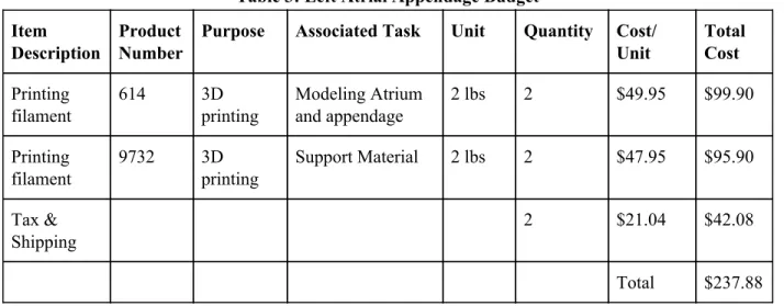
The budget was updated on March 6th, the budget modifications are reflected below.
Table 3: Left Atrial Appendage Budget
Item Description
Product Number
Purpose Associated Task Unit Quantity Cost/ Unit
Total Cost
Printing filament
614 3D printing
Modeling Atrium and appendage
2 lbs 2 $49.95 $99.90
Printing filament
9732 3D printing
Support Material 2 lbs 2 $47.95 $95.90
Tax & Shipping
2 $21.04 $42.08
Customer Requirements
Our customer requirements came from multiple interviews with Dr. Porterfield. We used the Quality Function Deployment method of coming up with these requirements. We first identified our customers, Dr. Porterfield and any other doctor/operator that might want to print a model. Through interviews we collected the requirements he desired and used a conjoint analysis along with more questions to figure out which were most important. The requirements we came up with along with Dr. Porterfield were; ease of use, time, production cost, shape/accuracy, repeatability and reproducibility. We conducted a patent search to determine what already exists for this procedure to determine which areas could be targeted for our growth as well.
Specification Development
After coming up with requirements we put numeric values to our qualitative specifications. With Dr. Porterfield, we brainstormed what max/min values would be acceptable for the 3D model. These values guided the design of the engineering specifications. With numeric values, we then designed experiments of how to test for these values and confirm our model is within our specifications. The specifications and experiments are listed below. Further information is seen in Table 4.
○ Ease of use: Ease of usewill be evaluated with physician feedback. 3 physicians will rank the procedure of how to convert the CT scan into an stl file, upload it to the printer and print the complex. They will rank the procedure on a scale of 1-10, with one being very easy to use and 10 being difficult to navigate.
○ Time: The entire print must be able to be completed in less than 1 day in order, which will be timed to confirm.
○ Production Cost: Each print must cost less than $50. Material cost and labor per unit will be recorded.
○ Shape: The print itself will be compared to the CT scan in order to confirm accuracy. 3 critical measurements (depth, volume and appendage opening diameter) of the complex will be measured and the percent difference from the CT scan will be calculated. The percent difference must be less than 10% on each measurement in order to confirm accuracy.
Table 4: Engineering Specifications
Specification Parameter Description
Requirement/Target Tolerance Risk Compliance
1 User Ease Physician evaluation must rank <3 (1 easy - 10 hard)
Max L T
2 Reproducible Procedure
No statistical difference in ANOVA
Max M T, A, S
3 Repeatable Procedure
No statistical difference in ANOVA
Max M T, A, S
4 Time 1 day Max L A
5 Production cost $50 Max L A
6 Shape <10% difference from CT scan
± 5% H T, A, I
Figure 2: House of Quality
Total Available Market
0562T. We estimated $75 per code, based on 0561T in conjunction with 0562T, there is a $13,500,00 billing potential.
Competitive Advantage
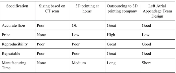
Our design can focus on many aspects that our competitors don’t possess. While there are many companies that 3D print organs from CT scans, such as Embodi3D and 3D Systems, none specifically focus on individual left atrial appendages. We will aim to make our 3D print faster, cheaper and use software to make it as accurate. Making this procedure repeatable and reproducible will help make it more competitive as well. There aren’t specific companies we are competing with for this project since it's specific to one anatomy and one procedure. Our competition is existing procedures and standards for sizing the Watchman. Currently doctors estimate the size based on CT scans, which can be inaccurate. This procedure can make sizing, consistent and accurate, preventing any second attempts of the procedure with the Watchman. Below in Table 5 is a competitor matrix, comparing our goal procedure with existing standards.
Table 5: Competitor Matrix
Specification Sizing based on CT scan
3D printing at home
Outsourcing to 3D printing company
Left Atrial Appendage Team
Design
Accurate Size Poor Ok Great Good
Price None Low High Low
Reproducibility Poor Poor Great Good
Repeatable Poor Poor Great Good
Manufacturing Time
None Medium Long Short
Intellectual Property Assessment
Table 6: Current and Relevant Patents and Patent Applications
Patent Number
Claim Addressing Claim
Patent 1 10,409,235 Method of printing model in a base & orientation that’s not the anatomical orientation
Use a 3D printer that has two extruders, one with a water-soluble material such as PVA to act as a base material to be able to print the model in the anatomical orientation of the patient.
Patent 2 10,417,804 Converting the medical image data from DICOM compatible data to another image data format when producing the first rendered medical image.
Keep the medical image data in DICOM format through the first rendered medical image, won’t convert the file to STL or any other file not compatible with DICOM until all segmentation and meshing is completed.
Patent 3 10,438,357 Claim three describes image segmentation processes that include determining the boundaries of the medical image by manually adding boundaries.
Determine anatomical model boundaries through pixel density in the image.
Patent Applicatio n 1
62634935 Intracardiac echocardiology as the two-dimensional imaging format that is to be converted into
three-dimensional.
For our project, we would want the method to include CT scans as a form of two-dimensional images.
Patent Applicatio n 2
14/833165 Printing with a three-dimensional printer an implant-related device based on the model of the anatomic structure of the patient.
To combat this we cannot refer to our design as “implant related”. Insted we will describe it as for instructional use and preoperative planning rather than aiding the implant itself.
Patent Applicatio n 3
16/349238 “A method for estimating the volume of an atrium (left (LA) or right (RA)) based on a plurality of emission tomography images, such as positron emission tomography images or single-photon emission computed tomography images, said method comprising the steps of..”
Conjoint Analysis
A conjoint analysis is a market research statistical tool that aids in identification of product characteristics that are important to the customer. In this conjoint analysis, four factors or attributes were assessed by fourth year biomedical engineering students instead of actual intended users. Each factor had three levels. Below we have Tables 7, 8 and 9 which display our factors and levels, the conjoint table and the description of the 9 choice cards. Because this conjoint analysis was completed with fourth year biomedical engineering students rather than actual intended users, the results of this conjoint analysis will not steer our decision making and the factors and levels were instead discussed with our sponsor, the intended user
.
Table 7: Factors and Levels.
Factor Level 1 Level 2 Level 3
Software ImageJ-Fiji 3D Slicer SegD Material Flexible PLA TPU ABS Time <1 day 1-3 days 3-7 days Printer Ultimaker Makerbot Replicator+ LulzBot Mini2
Table 8: Conjoint table on X and Y values.
Y x1-Software (ImageJ) x2-Software (3D Slicer) x1-Material (PLA) x1-Time (<1day) x2-Material (TPU) x2-Time (1-3 days) x1-Printer (UltaMaker) x2-Printer (makerBot)
1 1 0 1 1 0 0 1 0
2 1 0 0 0 1 1 0 1
3 1 0 1 1 0 0 1 0
4 0 1 1 0 0 1 0 0
5 0 1 0 0 1 0 1 0
6 0 1 0 1 0 0 1 0
7 0 0 1 0 0 0 0 1
8 0 1 0 1 0 0 1 0
Table 9: Description of Choice Cards.
Choice Cards Description
1 ImageJ-Fiji, Flexible PLA, <1Day, Ultimaker 2 ImageJ-Fiji, FTPU, 1-3 days, Makerbot Replicator+ 3 ImageJ-Fiji, ABS, 3-7 Days, LulzBot Mini2
4 3D Slicer Flexible PLA, 1-3 Days, LulzBot Mini2 5 3D Slicer, TPU, 3-7 Days, Ultimaker
6 3D Slicer, ABS <1Day, Ultimaker
7 SegD, Flexible PLA, 3-7 Days, Makerbot REplicator+ 8 SegD, TPU, <1 Day, LulzBot Mini2
9 SegD, ABS, 1-2 Days, Ultimaker
Statistical Summary:
Figure 3: Conjoint Analysis results
Interpretation of Results:
software with TPU material but doesn’t think the time to produce the model or the printer used are important.
Morphology
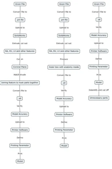
Our morphology chart is shown in Appendix 2. It describes all the features that our design might use based on different key functions. The figure below shows different concepts we generated from the morphology. Each concept takes prominent features and combines them in logical pathways. Our concepts are not sketches of models, but rather the possible procedures to follow to result in the 3D printed model.
Concept descriptions are as such:
Concept 1 (left): This concept utilizes extra steps between the given file and the stl file, the process includes converting the given file into a prt file to upload to solidwork to modify the model before printing. This added step in the process extrude cuts unnecessary heart features to reduce printing time and wasted material. An additional step in this procedure requires the body to be cut about the coronal plane to improve visual after print, and adding joining features to line up the model when needed.
Concept 2 (middle): This concept also includes converting the file to a prt file and importing it to solidworks and cutting out unnecessary heart features to ultimately end up with an outer box with the necessary anatomy on the inside.
Concept 3 (right): Concept 3 does not require an extra conversion of file between the given file and the stl file. The given file will be converted to an stl file and then uploaded to the printer software without any model modifications before print. 3It can be modified after the print by cutting off unnecessary parts.
Concept Evaluation (Pugh Chart)
To evaluate our concepts, we used a Pugh Chart. The Pugh Chart compared the concepts to each other based on our customer specifications and our QFD. Pugh’s Method provides a complex pro-con analysis and is applied to multiple concepts simultaneously. Each member of the team performed each chart on their own, each chart had each alternative as the baseline. When scoring on the Pugh Chart, the other two concepts were scored in relation to the concept that was used as a baseline. At the end of each chart, each concept’s score was tallied and compared. The results were then viewed by the team, all Pugh charts done by the 3 team members are shown in Appendix 3.
After evaluating the options with the Pugh Charts, Concept 2 shows the most promising results. While there were differing opinions between our team of how much design varied, most ranked Concept 2 highest. It has above the normal accuracy and it is easier to use than Concept 1 which requires more SolidWorks input. Concept three lacks the same reproducibility as the Concept 1 and 2. Concept 2
consists of converting the given file to a .prt file and uploading to SolidWorks. We then would extrude cut off all unnecessary potions of the CT can shorten print time. The bottom of the 3D model would be open to allow visuals going in. It doesn’t require much extra work in SolidWorks and no after print
modifications.
Conceptual Model
Description:
Watchman, a device used to close the left atrial appendage. Local physician, Dr Chris Porterfield struggles to select which Watchman size to select based solely off CT scans and would like a physical model to place the Watchman into.
The CT scan will be given to use as an .stl file and converted into a .prt file to edit the CT scan within SolidWorks to only possess needed anatomy. This will lower the print time since less material will be used. It will also make it easier to see the targeted anatomy. A hole will be cut at the mitral valve so the Watchman can be placed inside the appendage. The part will be checked for proper cuts and sizing within SolidWorks before proceeding. The file is then converted to an .stl and uploaded to the printer. Printer settings are predefined and outlined in the procedure. The printed model will be checked at critical measurements to ensure the .prt file in SolidWorks to ensure sizing was correct. The percent difference between the model and SolidWorks will be analyzed to see how well the model matches the scan.
Since we do not currently have the appropriate program or initial file for the 3D printing procedure, we created a procedure of what we think will occur with an arbitrary SolidWorks part we created. We will be starting with the image as a .stl or .dxf file and uploading it to SolidWorks to be altered. Dr. Porterfield will later provide a different kind of file that will add steps before converting to a .prt file.
Procedure:
1. Convert .stl file rendered from CT scan into a .dxf file using MeshLab i. Open .stl file in MeshLab
ii. Drop down “File” menu iii. Click on “Export Mesh As”
iv. Drop down “Files of Type” menu and select .dxf
v. Save file with the same name as .stl file in the same folder for organization purposes
2. Upload .dxf file into SolidWorks a. Drag .dxf file into SolidWorks
b. The DXF/DWG Import tool will appear:
i. Select “Create new Solidworks drawing”, “Convert to SolidWorks entities,” “Import to a new part as:” and “3D curves or model”
ii. Select “Finish” and wait for SolidWorks to process the file ** this will take up about an hour **
Note: The mesh has been converted to multiple surfaces
3. Identify which sections of the heart to keep by referring to anatomical models a. Correctly identify the left atrium and left atrial appendage
4. Extrude cut out unnecessary sections of the heart
Figure 5: Solidworks anatomy trimmed
6. Check part to ensure left atrium and left atrial appendage have not been removed 7. Convert file to .stl
a. Select “File”-”Save As” and changed file type to .stl 8. Upload file to 3D printer software: Ultimaker Cura
a. Define as seen in Figure 2 below: i. Infill
ii. Quality iii. Shell iv. Material
v. Speed vi. Cooling
Figure 6: Ultimaker Cura setting
9. Upload and modify printer settings a. Load filament into machine
b. Press “Bed”-”Heat” to heat up system
i. Check temperature of nozzle and plate by pressing “Bed/Extrude” on the printer panel
ii. Press “Print”- find file (file will have settings listed first then file name) iii. Confirm “Yes”
iv. Wait for plate to finish heating up and clear any extra plastic from platform c. Wait for first layer of print to be printed before leaving print alone
Note: This is important to ensure the print will print appropriately because most failures occur in the first layer if they were to occur
10. Allow the printer 1.5x the estimated time of the print
Figure 8: Final example print 11. Remove any support brims
12. Check length and volume measurements from SolidWorks 13. Collect length and volume measurements from model 14. Compare percent difference
a. Must be below 10% difference
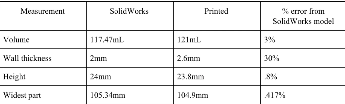
Analysis:
To ensure our procedure matches the dimensions of the printed model, we measured the
Table 10: Measurements and percent error
Measurement SolidWorks Printed % error from SolidWorks model
Volume 117.47mL 121mL 3%
Wall thickness 2mm 2.6mm 30%
Height 24mm 23.8mm .8%
Widest part 105.34mm 104.9mm .417%
All measurements except the wall thickness were within our 10% error specification. Wall thickness difference could be due to improper printer settings. We tried a standard setting for wall thickness to allow for a more stable structure.
For the procedure, many more steps need to be added to account for the procedure difficulties with file conversion. We began our procedure with a .prt instead of an .stl, which made steps much easier than we expect to do.
What We Learned:
We learned that there are many more steps involved in converting the file to a .prt than we originally thought. Issues arose when large .prt or .stl files couldn’t be uploaded into SolidWorks. After research we realized that SolidWorks only accepts files that have less than 20,000 facets. This may become an issue later on if CT scan files are too large. We might have to backtrack and have files that Dr. Portfield provides for us more edited and processed to be the correct anatomy. The mesh created from the CT scans is also too refined for SolidWorks capabilities so we had to bypass Solidworks’ built in file conversion from .stl to .prt. We may have to use another software and file type between the CT scan data and importing into SolidWorks, MeshLab, which is an open source software needed to convert the stl file into a dxf file before importing to SolidWorks.
During the printing procedure we learned how specific the settings need to be in order to get the proper result with wall thickness being a main focus of our next print.
Future Development:
We plan to research and proceed with another 3D modeling software that has larger file capabilities than SolidWorks. If this does not work, we will have to leave behind this process and continue with a modification of one of our other two processes. Continuing with a different process will mean that we will have longer printing times than we hoped for due to the inability to modify the model to eliminate unnecessary features that may be driving printing time up.
to adjust settings. Based on the data from the CT scans and provided three-dimensional renderings, we will have to determine if we need to extrude any common pieces of the heart that are not essential to the goal of this project.
Since there were conversion difficulties with files we initially assumed would not be an issue, we will need to make sure that we clearly define the file conversion aspect of our final process. We will need to make a decision on what files can be used for our process to make sure that the operator can save the renderings in the appropriate file type. At this point, accurate file conversions is our main issue that we will coordinate with Dr. Porterfield’s assistant Sarah to ensure an efficient solution.
Conclusion:
Our model development brought awareness to challenges that our team did not foresee. These challenges occurred in our extrusion of unnecessary features which we believed would be rather simple. Our team will go ahead and refine this process still including the extrusion of unnecessary material. If we do not find methods to do so, we will go ahead and proceed with one of our other processes that does not include this feature.
Detailed Design
The process we will proceed with for the final design will consist of using 3D Slicer to segment CT scans in an attempt to virtually isolate the right atrium, left atrium, and left atrial appendage which will be printed using a 3D printer. The model will allow physicians to accurately size the appendage and accurately estimate the entry trajectory angle. Originally we were to extrude unnecessary tissue and anatomy from the virtual model using Solidworks from .dcm files. However, we have decided that we will be taking raw CT scans and segment them using 3D slicer to our specified requirements. After following the procedure described in the Prototype Manufacturing Plans section, the virtual model that will be printed will look similar to that in Figure 9 below.
Since we are using printing resources provided by Cal Poly, the cost estimation only consists of the filament used by the 3D printers. The prints we are currently processing are done on the Ultimaker printer in the BMED Lab which require PLA and PVA filament that will cost $118.94 after tax and shipping. Since this process creates a model that is used for sizing, the dimensions of the model must be identical to the anatomical measurements of that patient. We will use the Ultimaker printer to determine the potential of accuracy that 3D printing these models can be with a higher end printer. Since most offices including those in French Hospital will not allocate a large amount of money for 3D printers, we will use cheaper printers for future prints because we want to ensure we update our printing settings to compensate for lack of quality of the cheaper printers. This will decrease the cost estimate of future prints. The diagram below explains the overall process from CT scan to print. The main ideas behind each of these steps will remain the same, though the smaller details may change as we continue to update our procedure.
Figure 10: Manufacturing Process flowchart
Prototype Manufacturing Plans
CT scans would have been taken and saved as stackable DICOM files prior to this method.
Figure 11: Loading DICOM b. Select “Import”.
Figure 12: Importing data
Figure 13: Select patient file
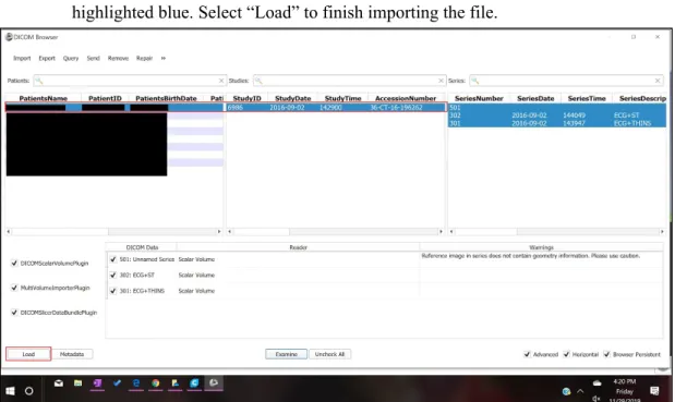
d. Your patient will populate the first row of the list, select that row until your patient is highlighted blue. Select “Load” to finish importing the file.
Figure 14: Loading data
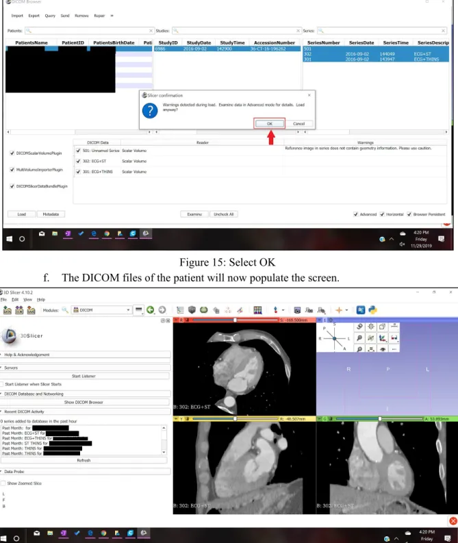
Figure 15: Select OK
f. The DICOM files of the patient will now populate the screen.
Figure 16: Screen display
Figure 17: Labeled views
3. In order to make a 3D model from the numerous slices contained in the DICOM files, the segment editor will be used for editing and cropping to only select the left atrium and the left atrial appendage. The tools in the segment editor that will be used are “Threshold”, “Scissors” and “Hollow”.
a. In the Segment Editor, select “Threshold” from the “Effects” menu.
b. After selecting “Threshold” the menu for “Threshold” appears as seen below, adjust your settings to similar ones to this tutorial. Select “Apply” when this range is selected.
Figure 19: Select threshold parameters
c. Before proceeding with the edits in the segmenting tool, change the slice in the “Axial” view so that the left atrium and the left atrial appendage can be clearly seen, use the slider at the top of the Axial view to change the slice.
Figure 20: Labeled CT scan
Figure 21: Select scissor feature
e. After the scissors are applied, then a 3D model can be rendered from the cropped slices. Select “Show 3D”.
Figure 22: Select Show 3D feature
Figure 23: Change views
4. The 3D image populates the entire screen for further cropping in the 3D view.
Figure 24: Uncropped 3D model
Figure 25: Select Hollow feature b. Now select “Scissors” and crop out unnecessary anatomy.
Figure 26: Select scissor feature
Figure 27:Labeled left atrial appendage
d. Crop until you have a simple geometry left that still shows the left atrial appendage and the left atrium. When cropping, consider cropping a top portion of the left atrium to have for viewing the left atrial appendage from the inside.
Figure 28: Cropped 3D model
Figure 29: Export 3D model as an .stl
f. After selecting “Export to Files…” select a Destination Folder. We advise you to select a folder that contains this particular patient’s files. Before selecting export, make sure that the file format chosen is “STL”. Select export.
Figure 31: 3D model in Ultimaker Cura software a. Define as seen in Figure 10 below:
i. Infill ii. Quality iii. Shell iv. Material
v. Speed vi. Cooling
Figure 32: Ultimaker Cura Setting
i. Load filament into machine
ii. Press “Bed”-”Heat” to heat up system
1. Check temperature of nozzle and plate by pressing “Bed/Extrude” on the printer panel
2. Press “Print”- find file (file will have settings listed first then file name) 3. Confirm “Yes”
4. Wait for plate to finish heating up and clear any extra plastic from platform
c. Wait for first layer of print to be printed before leaving print alone
Note: This is important to ensure the print will print appropriately because most failures occur in the first layer if they were to occur
2. Allow the printer 1.5x the estimated time of the print. 3. Remove any support brims
4. Check length and volume measurements from SolidWorks 5. Collect length and volume measurements from model 6. Compare percent difference
a. Must be below 10% difference
Bill of Materials
Table 11: Bill of Materials
Bill of Materials
Product: Left Atrial Appendage Model Date: 12/1/2019
Assembly: 3-D Print
Item # Part # Qty Name Material Source 1 1614 2 Printing filament PLA Amazon 2 9732 2 Printing filament PVA Amazon 3 4.10 and above 1 3D Slicer Software slicer.org
Team member: Brandon Mukai Prepared by: Brandon Mukai
Team member: Areli Reyes Checked by: Areli Reyes
Team member: Mia von Knorring Approved By: Mia von Knorring
Final Manufacturing Process Instructions
Operation Manual
Our Operation Manual, shown in Appendix 5 expands on features of the MPI. It describes what commands do and how to properly use them. It should be used as a supplement to the MPI to further understand the slicing procedure.
Training Guide
Before operators are authorized to perform the MPI for sizing the Watchman device, they must prove their ability to follow the procedure correctly. We have created a Training Guide, which can be found in Appendix 6 that must be followed to be checked off. The Training Guide is the same document as the MPI, but instead of printing the entire left atrium and left atrial appendage, the user will be printing ⅓ of the left atrium with the left atrial appendage. One patient CT scan is referenced in the training guide, here the user will perform measurements on the left atrial appendage they print and then determine the sizing of Watchman for that patient. They will only pass the training if they determine the appropriate size watchman for that patient, which will already be sized beforehand.
In addition to the Training Guide, there is the Training Completion Form, Appendix 7, which will be used to document which users are authorized to use the MPI for sizing the Watchman device.
Test Protocols
Testing Overview:
There are 3 parts to the Left Atrial Appendage Testing:
1. User Feedback- Dr. Porterfield and Sarah will follow procedure and take a survey of different features to obtain feedback on user experience (n=2 operators on n=1 trials). They must rank each feature 1-10 (1 easy, 10 hard). All features must obtain < 3.
2. Model Accuracy- We will segment and print 3 models, each with a different CT scan (n=3). We will then select which Watchman size based on our model. This selection will be based on appendage diameter and depth. Dr. Porterfield will then look at the CT scan and choose the Watchman size (current sizing method).
Protocols:
1. User Feedback1. Dr. Porterfield and Sarah (operators) both train to Training Protocol 2. Operators follow MPI and Operational Manual
a. Operators segment the CT scan in 3D slicer and convert into an .stl file
b. Operators upload .stl file to Ultimaker Cura Software and input correct settings
c. Operators print the appendage on any 3D printer compatible with the Ultimaker software 3. Operators take the following survey.
1 is the best ranking and 10 is the worst.
Question Ranking Comments
Was the MPI formatted in an easy-to-follow design?
1 2 3 4 5 6 7 8 9 10
Does the training adequately access operator proficiency?
1 2 3 4 5 6 7 8 9 10
Were directions clear? 1 2 3 4 5 6 7 8 9 10
Was our method of isolating the left atrium and left atrial appendage efficient?
1 2 3 4 5 6 7 8 9 10
Could you easily locate the left atrial appendage from MPI instructions?
1 2 3 4 5 6 7 8 9 10
Did the Operation Manual explain each tool’s purpose clearly?
1 2 3 4 5 6 7 8 9 10
Was the printing process easy to understand from the training guide and MPI?
1 2 3 4 5 6 7 8 9 10
2. Model Accuracy
1. Operators follow the Left Atrial Appendage Manufacturing Process Instructions with 3 patient files
a. Operators segment the CT scan in 3D slicer and convert into an .stl file
b. Operators upload .stl file to Ultimaker Cura Software and input correct settings c. Operators print the model on the BMED 3D printer
Figure 34: Boston Scientific Watchman sizing chart
3. Dr. Porterfield will choose the Watchman size based on examining the CT scans (current industry standard method).
4. Selection of the Left Atrial Appendage Team must match 100% that of Dr. Portfield.
3. ANOVA
1. Train operators on 3D slicer according to Training Protocol
2. 3 operators follow the Left Atrial Appendage Manufacturing Instructions with one patient file a. Operators segment the CT scan in 3D slicer and convert into an .stl file
b. Operators upload .stl file to Ultimaker Cura Software and input correct settings
c. Operators print the appendage on any 3D printer compatible with the Ultimaker software 3. Operators take 3 critical measurements on the printed model
a. Volume
i. Operators use a 10mL graduated cylinder to slowly fill the appendage with water. Operators fill the appendage up to the ostium. Operator records how many mL it took to fill the appendage.
b. Depth
i. Operators use calipers to measure the depth of the appendage up to the ostium c. Widest diameter
i. Operators will use calipers to measure the widest diameter in the opening of the appendage
Figure 35: Ostium measurement 4. Operators repeat the procedure 2 more times.
Note: Each segmenting and printing repetition should be done on a different day
a. No statistical difference between operators and trials for repeatability and reproducibility with a p value of 0.05 concludes that the procedure is valid
Testing Details:
FacilitiesAll operators have 3D slicer on their computers. The .stl will be uploaded to the Ultimaker software. Both are open source software that can be downloaded to any computer. The appendage models will be printed in the BMED 3D printing lab using PVA and PLA filament or in the Mustang ‘60
Machine Shop using just PLA. Measurements will be taken in the BMED 455 Lab classroom using calipers and 10mL graduated cylinders. The appendages will be cut with a saw if necessary in the Mustang ‘60 Machine Shop.
Equipment:
We will be using the 3D Slicer software to segmentand the Ultimaker Cura software to upload to the printer. Any printer compatible with Ultimaker Cura software can be used for the procedure, but we will be using the BMED printer in Engineering IV with PVA and PLA filament. Calipers and a 10mL graduated cylinder will be used to make measurements.
Bill of Materials:
Will be using PLA filament and PVA filler filament to produce our models.
Training:
All operators must be trained how to use 3D Slicer and the Ultimaker software. All operators will follow the Training Guide to print a standardized appendage. The printed appendage must match the dimensions of the standardized model. A manager will sign the Training Completion Form if the printed appendage is <10% different from the standardized model.
Testing Data and Analysis
User Feedback Survey:
Dr. Porterfield’s Survey
Question Ranking Comments
Was the MPI formatted in an
easy-to-follow design?
1
2 3 4 5 6 7 8 9 10N/A
Does the training adequately
access operator proficiency?
1
2 3 4 5 6 7 8 9 10N/A
Were directions clear?
1
2 3 4 5 6 7 8 9 10 N/AWas our method of isolating the left atrium and left atrial
appendage efficient?
1
2 3 4 5 6 7 8 9 10 N/ACould you easily locate the left atrial appendage from MPI instructions?
1
2 3 4 5 6 7 8 9 10 N/ADid the Operation Manual explain each tool’s purpose clearly?
1
2 3 4 5 6 7 8 9 10 N/AWas the printing process easy to understand from the training guide and MPI?
Sarah’s Survey
Question Ranking Comments
Was the MPI formatted in
an easy-to-follow design?
1
2 3 4 5 6 7 8 9 10Great!
Does the training
adequately access operator proficiency?
1
2 3 4 5 6 7 8 9 10 N/AWere directions clear?
1
2 3 4 5 6 7 8 9 10 N/AWas our method of
isolating the left atrium and left atrial appendage efficient?
1
2
3 4 5 6 7 8 9 10 Might have been more efficient with a tighter threshold in certain CTs. Would be helpful to know how to segment/reassign the LAA off of the LA and turn “on” and “off” for editing purposes.Could you easily locate the left atrial appendage from MPI instructions?
1
2 3 4 5 6 7 8 9 10 Good use of different viewsDid the Operation Manual explain each tool’s purpose clearly?
1
2 3 4 5 6 7 8 9 10 Very helpful.Was the printing process easy to understand from the training guide and MPI?
1 2
3
4 5 6 7 8 9 10 Only giving this a 3 because I had to figure out the settings on my own. Could have been a different version?ANOVA Results:
Figure 36 and 37: Volume measurement set-up
Figure 38 and 39: Depth (left) and diameter (right)
Table 12: Appendage Measurement Testing Results
Operator Model Number Depth (mm) Diameter (mm) Volume (mL)
Operator 1 (Mia)
1 35.1 22.8 9.8
2 36.1 22.5 12.2
3 35.4 22.5 9.8
Operator 2 (Areli)
1 34.8 23.7 9.7
2 34.4 21.1 9.6
3 33.5 24.2 9.5
Operator 3 (Brandon)
1 35.4 23.4 9.7
2 36.1 24.3 9.6
We ran an ANOVA study in Minitab with our 9 models to find the repeatability with the same operator and reproducibility between operators for all 3 measurements. Minitab results are shown below:
Table 13: ANOVA Results
Operator Test P- Value Statistical Difference
Conclusion
Volume Reproducible .290 No Passed Repeatable .401 No Passed
Diameter Reproducible .404 No Passed Repeatable .592 No Passed
Depth Reproducible .036 Yes Failed Repeatable .271 No Passed
Model Accuracy:
Figure 40 displays the measurements taken directly off the CT scan on 3D slicer. Table 14 displays the model accuracy results.
Table 14: Model Accuracy results
Measurement 3D Model Result CT Scan Results
Model 1 Model 2 Model 3
Diameter average (mm) 22.6 23 23.9 21.8
Depth average (mm) 35.53 34.23 35.66 29.1
Volume average (mL) 10.6 9.6 9.53 10.5
Watchman Sizing 27 27 27 27
Diameter % different from CT Scan
3.6% 5.37% 9.2% N/A
Depth % different from CT Scan
19.87% 16.2% 20.25% N/A
Volume % different from CT Scan
.94% 8.95% 9.68% N/A
Conclusion
3 measurements had a <10% difference to the CT scan. The 3D printed model had a <10% difference in volume and diameter, but had a 18.8% difference in depth. After discussing this result with Dr.
Porterfield, we concluded that this measurement is subjective and hard to keep consistent. The depth is not critical to the Watchman sizing and with the diameter and volume having very low percent
differences, our model can still be verified as accurate.
Discussion
Overall, this procedure accurately modeled the left atrial appendage in order to properly size the Watchman. Many improvements could be done to this procedure to produce even more accurate and consistent results including modifying the “threshold” feature range per patient. In 3D slicer, we chose a range of pixel density that encompassed most of the left atrium and left atrial appendage, but this could vary based on different CT scan paraments. Perhaps not all CT scans were obtained with the same machine or transfering the .DICOM files changes pixel quality. To improve this, we would add in a broader threshold range and have the operator modify it based on visually noting where the boundaries of the left atrium and appendage lie. This requires more operator training to be able to identify the proper anatomy and adds another factor of variability to the model. Our project was also limited by the software available and chose to use 3D Slicer instead due to its ease of use and free access. However 3D Slicer is not proven or validated for clinical use. When opening up the application the message “This software is not intended for clinical use” appears. To further improve and validate the procedure, the procedure can be done using the Abbott, EnSite Precision. EnSite Precision is currently used in operating rooms performing electrophysiology procedures. Using filament with tissue-like properties could also help with sizing the Watchman. More flexible material is clinically relevant and could allow doctors to see the compression the Watchman could cause on the appendage to ensure that the device is correctly sized.
Many sections of the procedure create variability that could change procedure outcomes. While our ANOVA demonstrated overall consistency between operators and trials, there could be variability in printer operator. We had the same lab assistant print all of our models, but he created certain parameters and printer features for all his prints that could possibly change between operators. To mitigate this risk, we recorded all notable parameters in our procedure. Variability could also arise when anatomy is being cropped. Operators could remove too much necessary anatomy or include more anatomy to create a larger model. In some patients, the pulmonary arteries are in close proximity to the left atrial appendage. When cropping, one operator selected this feature as part of the left atrial appendage, creating an outlier in the data. We discussed this with Sarah Griess, Dr. Porterfield’s clinical specialist, and she stated her position is specifically traned to look out for this anatomical phenomenon. We added a note in the MPI for operators to recognize the two features and ensure they are not grouped together.
Appendix:
Appendix 1: Table of Deliverables
Deliverable
Date
Team Contract 9/24/2019
Intellectual Property ID 10/8/2019
Conjoint Analysis Report 10/10/2019
House of Quality 10/10/2019
Network Diagram 10/10/2019 Statement of Work/IFU 10/10/2019 Budget 10/10/2019 Project Requirements
Document 10/15/2019 Project Plan Meeting 10/15/2019 Project Plan Meeting 10/17/2019 Pugh Chart 10/22/2019 Conceptual Model 10/29/2019 Status Update Memo 10/29/2019 Hazard and Risk Assessment 10/30/2019
Conceptual Design Prototype 11/04/2019-11/07/2019 Status Update Memo 11/12/2019
Peer Evaluations/Team Health
Assessment 11/12/2019 Yellow Tag Test Complete 11/14/2019 Status Update Memo 11/18/2019 Critical Design Review
Presentation 12/02/2019-12/05/2019 Design Notebook Progress
Status Update Memo 1/21/2020
Functional Prototype Demo 01/27/2020-01/30/2020 Test Plan Presentation 1/27/2020
Test Plan Report 1/27/2020 Functional Prototype Video 1/27/2020 Status Update Memo 2/3/2020 Peer Evaluations/Team Health
Assessment 2/3/2020 Status Update Memo 2/10/2020 Status Update Memo 02/18/2020 Status Update Memo 02/24/2020 Status Update Memo 03/02/2020 Demo Day/Design Review
Presentations 03/09/2020-03/12/2020 Senior Project Design Report 03/09/2020
Design Notebook Due 03/16/2020 BMED Expo Poster
Appendix 2: Morphology
Morphology
Product: Left Atrial Appenda Printing Process
Organization Name : Left Atrial Appendage Team
Function
Concept 1
Concept 2
Concept 3
Concept 4
Determining face t
print Use biological marke to find face to slice
Use coordinate system to find fa
to slice Use judgement
Converting to PRT
file Straight from CT file
Extrude unnecessar
features Solidworks Fusion
Converting to STL
file Mimics
From given
software Solidworks Fusion
Printing anatomica body
3D print whole heart
Trim image then 3D print only
necessary parts
Visibility
Transparent material/1 whole body
Split in half abou the coronal plane
Split in half about the sagittal plane
1 whole body, mitral valve & tricuspid valves opened
Team member: Mia von Knorring
Team member: Brandon Mukai Prepared by: Areli Reyes Team member: Areli Reyes Team member: Brandon Mukai Checked by: Mia von Knorring Approved by:
The Mechanical Design Process Designed by Professor David G. Ullman Copyright 2008, McGraw Hill
Appendix 3: Pugh Charts
Mia
Mia
Concept 1 Concept 2 Concept 3 Issue: Choose a design/procedure to
3D print the left atrial appendage
Accuracy 40
Datum
0 -1
Easy of Use 20 1 1
Time 10 -1 1
Reproducibility 15 0 -1
Repeatability 15 0 -1
Total 0 -1
Weighted Total 10 -40
Concept 2 Concept 1 Concept 3 Issue: Choose a design/procedure to
3D print the left atrial appendage
Accuracy 40
Datum
0 -1
Easy of Use 20 1 1
Time 10 -1 1
Reproducibility 15 0 -1
Repeatability 15 0 -1
Total 0 -1
Weighted Total 10 -40
Concept 3 Concept 2 Concept 1 Issue: Choose a design/procedure to
3D print the left atrial appendage
Accuracy 40 1 1
Easy of Use 20 -1 -1
Reproducibility 15 1 1
Repeatability 15 1 1
Total 1 1
Weighted Total 40 40
Areli
Areli
Concept 1 Concept 2 Concept 3 Issue: Choose a design/procedure to
3D print the left atrial appendage
Accuracy 40
Datum
1 -1
Easy of Use 20 -1 1
Time 10 1 1
Reproducibility 15 1 1
Repeatability 15 1 1
Total 3 3
Weighted Total 60 20
Concept 2 Concept 1 Concept 3 Issue: Choose a design/procedure to
3D print the left atrial appendage
Accuracy 40
Datum
-1 -1
Easy of Use 20 -1 1
Time 10 -1 1
Reproducibility 15 -1 1
Repeatability 15 -1 1
Total -5 3
Weighted Total -100 20
Issue: Choose a design/procedure to 3D print the left atrial appendage
Accuracy 40
Datum
1 -1
Easy of Use 20 -1 -1
Time 10 1 -1
Reproducibility 15 1 -1
Repeatability 15 1 -1
Total 3 -5
Weighted Total 60 -100
Brandon
Brandon
Concept 1 Concept 2 Concept 3 Issue: Choose a design/procedure to
3D print the left atrial appendage
Accuracy 40
Datum
1 -1
Easy of Use 20 1 -1
Time 10 1 1
Reproducibility 15 1 -1
Repeatability 15 1 0
Total 5 -2
Weighted Total 100 -65
Concept 2 Concept 1 Concept 3 Issue: Choose a design/procedure to
3D print the left atrial appendage
Accuracy 40
Datum
-1 -1
Easy of Use 20 -1 -1
Reproducibility 15 -1 1
Repeatability 15 -1 1
Total -5 -1
Weighted Total -100 -40
Concept 3 Concept 2 Concept 1 Issue: Choose a design/procedure to
3D print the left atrial appendage
Accuracy 40
Datum
1 1
Easy of Use 20 1 0
Time 10 1 0
Reproducibility 15 1 -1
Repeatability 15 1 -1
Total 5 -1
Appendix 4: Manufacturing Process Instructions (MPI)
Slicing Procedure
1: Upload DICOM File into 3D Slicer
1.1: Select “Load DICOM Data” shown in Figure 1.
Figure 1
1.2: Select “Import” shown in Figure 2
1.3: This menu brings you to the files on the
computer, navigate your files and select the folder that contains all the DICOM files for the patient as shown in Figure 3.
Figure 3
1.4: Your patient will populate the first row of the list, select that row until your patient is highlighted blue. Select “Load” to finish importing the file as shown in Figure 4.