1
Pulsed Electric Field System Development for Algae
Biofuel Extraction
By: Aspyn Bessler and Juan David Gonzalez
Senior Project
ELECTRICAL ENGINEERING DEPARTMENT California Polytechnic State University San Luis Obispo
2
Table of Contents
Abstract ... 3
Introduction ... 4
Cultivation of Chlorella Vulgaris ... 4
Algae Lysis ... 5
Electroporator Design... 10
Requirements and Specifications ... 13
Electroporator Circuits ... 14
Mechanical Relay Electroporator ... 14
Solid State Relay Electroporator ... 21
Bill of Materials: Parts List ... 26
Conclusion ... 27
References ... 28
Appendix A: Mechanical Relay Electroporator Data ... 29
Appendix B: PEF Treatment Set Up Instructions... 34
3 Abstract
The search for sustainable alternatives to fossil fuels proves necessary due to the effects fossil fuels have on Earth’s environment. These alternatives must have a minimum ecological footprint and cause no long-term harm to the environment. An environmentally friendly fuel is necessary to usher in a generation of renewable green energy.
The production of algae refined biofuels becomes a possible solution to this growing issue. Algae absorb CO2 from the atmosphere during their reproduction and growth cycles,
yielding a positive environmental impact. As the biofuel is refined and becomes suitable for use, the combustion of the finished fuel generates an equal amount of CO2. Thus, yielding a net zero
environmental impact.
Algae biofuel is fabricated from the intracellular materials of algae cells. This report describes the application of pulsed electric fields (PEF) to algae for intracellular extraction. PEF treatments rupture the algae cell membrane allowing a centrifuge to extract lipid-rich contents from the interior cell. Fig. 1 shows the algae cell’s biochemistry.
4
Introduction
Cultivation of Chlorella Vulgaris
The research team harvests, conserves, and maintains Chlorella Vulgaris cultures in glass flasks placed on a digital shaker below florescent lighting, as shown in Fig. 2. The algae cultures are harvested from an original culture obtained from a vendor. The culture is then split to create additional cultures. When the culture is split, proper sanitation and sterilization lab procedures prevent the introduction of other organisms and pollutants. The split culture and media (Bold’s Basal Medium or BBM) are added to a newly sterilized flask. The flasks are sealed with aluminum foil and cotton, placed under fluorescent lighting, and given enough BBM to reproduce and grow freely. Multiple cultures with different maturity levels (culture age) are maintained to guarantee constant algae samples for testing. The small 25mL flasks are used because the PEF treatments performed in this report utilizebetween 0.3 - 0.5mL from the cultures. New C. Vulgaris cultures contain 9mL of algae media (BBM) and 1mL of a previous healthy culture (a culture without contaminants and low algae density).
5
Algae Lysis
Lysis Via Lyse-It kit
The cultivated cells of an algae sample before lysis are pictured in Fig. 3. The Biology team has achieved lysis using a Lyse-It™ kit, Fig 4a. [1] The results are compared to our lysis attempts with the designed Electroporator. The Lyse-It™ kit focuses microwave energy directly into a C. Vulgaris sample by utilizing single use slides. A foam gasket is attached to a Lyse-It™ slide with gold foil to focus the microwave energy directly into the sample. 1mL of algae is placed into the gasket and a plastic coverslip added. The sample is placed in the middle of the microwave oven and microwaved for 30 seconds with the power level set to 2 (20%). The C. Vulgaris cells after utilizing Lyse-It™ kit are represented in Fig. 4b.
FIGURE 3:CHLORELLA VULGARIS BEFORE LYSIS
6
7
PEF Treatment Chamber Design
Without a Lyse-It™ kit, the electric field necessary to rupture the algae cell wall is created by an electroporator device or pulse generator. Pulsed electric field (PEF) treatments are
accomplished by placing the algae in a constructed electroporator chamber. Fig. 5 shows the chamber we have constructed with Indium Tin Oxide (ITO) coated glass slides and Kapton tape.
FIGURE 5:TOP VIEW (LEFT) AND SIDE VIEW (RIGHT) OF THE CONSTRUCTED CHAMBER
FIGURE 6:ITOPEFTREATMENT CHAMBER
The PEF treatment chamber, Fig. 6, is assembled by clamping the two ITO conductive sides together. The ITO coating allows the glass slides to conduct electricity. The Kapton tape prevents the two ITO coated slides from touching. If the ITO coated slides touch, this would cause a short circuit that would destroy the chamber. The slides are connected to the
8
FIGURE 7:ELECTROPORATOR’S PEFTREATMENT CHAMBER DIAGRAM
The electric field in Fig. 7 is proportional to the voltage potential (1) between the slides and their calculated distance (2).
Vslides (Volts) = V+ - V- (1)
E (KV/cm) = Vslides (V) / d (μm) (2)
Subjecting the slides to a voltage potential from 0V up to 140V yields PEF intensities up to ~46.67(KV/cm), calculated using Equation (2). This method presents limitations that include: costly glass chamber fabrication (ITO glass slides cost $15 a piece) and possible short circuiting (ITO damage).
9
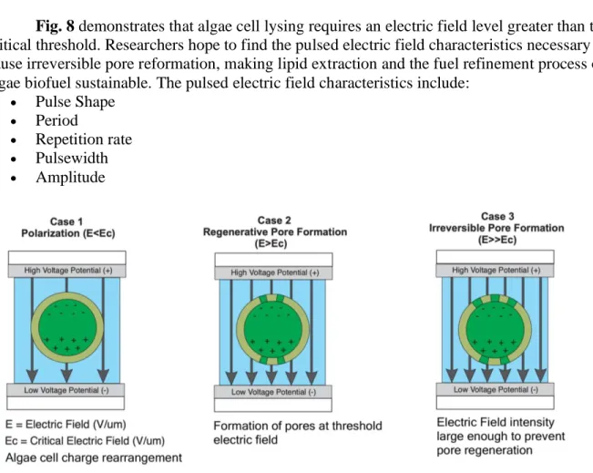
Fig. 8 demonstrates that algae cell lysing requires an electric field level greater than the critical threshold. Researchers hope to find the pulsed electric field characteristics necessary to cause irreversible pore reformation, making lipid extraction and the fuel refinement process of algae biofuel sustainable. The pulsed electric field characteristics include:
• Pulse Shape
• Period
• Repetition rate
• Pulsewidth
• Amplitude
FIGURE 8: POTENTIAL PEFTREATMENT CASES [4].
10
Electroporator Design
Algae Impedance Model
Previous research conducted by Cal Poly’s Algae Biofuel team concluded that the algae impedance can be represented by a combination of capacitance and resistance illustrated in Fig. 9. This model is not completely accurate because the algae impedance can vary based on algae concentration, volume, and sample size. The impedance model was derived to help with the simulation and construction of an electroporator device.
FIGURE 9:THEORIZED IMPEDANCE MODEL OF THE ITOCHAMBER WITH ALGAE
Equivalent Circuit Design of Electroporator
The Electroporator (Pulse Generator) device applies PEF treatments to an algae sample using the charging and discharging capabilities of a capacitor. The Level 0 Block Diagram of the system is in Fig. 10.
11
Fig. 11 describes the level 1 block diagram of the Electroporator circuit. Creating two Pulse Generator’s that utilize a mechanical relay and a solid-state relay. Equation (3) shows the RC time constant where the potentiometer is controlled by the user to obtain a specific tau (𝜏)
value.
𝜏 = 𝑅𝑝𝑜𝑡𝑒𝑛𝑡𝑖𝑜𝑚𝑒𝑡𝑒𝑟𝐶𝑠𝑡𝑜𝑟𝑎𝑔𝑒 (3)
FIGURE 11:LEVEL 1BLOCK DIAGRAM,ALGAE CELL LYSIS ELECTROPORATION SYSTEM
The equivalent circuit of our Mechanical Relay Electroporator device is shown in Fig. 12. The circuit shows a Power Source of 90V – 120V that is supplied to a 1kΩ Charging Resistor. When the relay is in the normally closed (NC) the supplied voltage goes through the Charging Resistor and into the Storage Capacitor to charge it. When the relay is switched to NO, the voltage in the Storage Capacitor is discharged across the constructed Algae Chamber in parallel with a Potentiometer. The Storage Capacitor is a fixed value in the circuit while the
12
FIGURE 12:ELECTROPORATOR MECHANICAL RELAY EQUIVALENT CIRCUIT
The second pulse generator is constructed with solid state relays (SSRs) controlled by an Arduino. The Arduino Code commands the pulse widths and allows a train of pulses to be injected into the algae. The SSR circuit leads to more issues such as a drop in voltage of 80% seen across the algae. This drop in voltage is due to the opto-TRIAC in the SSR and an
inaccurate impedance model of the ITO + algae. The equivalent circuit of the Solid State Relay Electroporator is shown in Fig. 13.
13
Requirements and Specifications
TABLE 1
SYSTEM REQUIREMENTS AND SPECIFICATIONS FOR ALGAE ELECTROPORATOR DEVICE
Marketing Requirements
Engineering
Specifications Justification
1, 3
Deliver pulses with microsecond widths, 1us-10us, voltages 90V-140V
and fields strengths of ~46.67[𝐾𝑉
𝑐𝑚]
Previous research to achieve algae lysis based on past studies [4] [5]
5 Source, 120V AC Available Power Sources
4
User controlled pulse characteristics: length, duration, voltage peak, frequency, and strength
Allows optimum combination for effective lysis
1, 3 Electroporator emits a pulse train with the specified user inputs.
Allows user to discharge more than a single pulse into the algae sample
Marketing Requirements
1. Adjustable output pulse characteristics 2. User-friendly interface
3. Accommodates different algae densities 4. Customer Safety
14
Electroporator Circuits
Mechanical Relay Electroporator
The mechanical relay circuit consists of a power source in series with a charging resistor with a value of 1 kΩ connected to the normally closed (NC) arm of the relay. When triggered, the relay switches to the normally open (NO) position and distributes the storage capacitors charge across the algae chamber and electroporator. The schematic of the circuit appears in Fig. 14.
FIGURE 14:ALGAE ELECTROPORATOR MECHANICAL RELAY CONFIGURATION CIRCUIT DIAGRAM
The relay in Fig. 14 is controlled by a NPN Relay Switch Circuit to help eliminate the bouncing from the relay’s mechanical arm. Bouncing occurs when the relay has first been switched but not yet settled, which can cause the circuitry to react as if the relay had been toggled multiple times. The NPN Relay Switch Circuit configuration is shown in Fig. 15.
15
The initial design of the circuit utilized a 1nF storage capacitor and 1 kΩ-3 kΩ
potentiometer value to achieve a time constant in the microsecond range. After testing the circuit, the results yielded a time constant in the millisecond range. Combining the measured time
constant results with the potentiometer value, calculated algae resistance is 125.8Ω - 128.5Ω using equation (4) and (5).
𝜏 = 𝑅𝑡𝑜𝑡𝑎𝑙𝐶𝑠𝑡𝑜𝑟𝑎𝑔𝑒 (4)
1 𝑅𝑡𝑜𝑡𝑎𝑙=
1 𝑅𝑎𝑙𝑔𝑎𝑒+
1
𝑅𝑝𝑜𝑡𝑒𝑛𝑡𝑖𝑜𝑚𝑒𝑡𝑒𝑟 (5)
A table of resistor values was calculated utilizing equation (4) and (5). The resistor values were calculated using an estimated value of 126 Ω for the algae sample, a time constant in the range of 1us-10us, and capacitor values between 1uF-1nF. These resistances represent the value the potentiometer should be set to when taking the resistance of the parallel algae sample into consideration.
TABLE 2
POTENTIOMETER RESISTANCES FOR SPECIFIED CAPACITOR AND TIME CONSTANT VALUES
1us 2us 3us 4us 5us 6us 7us 8us 9us 10us
1uF 1 2 3 4 5 6 7 8.5 9.7 10.0
0.1uF 10.9 23.8 39.48 58.6 82.9 114.6 157.5 129.1 315 485.6 0.047uF 25.6 64.25 129.4 262.2 683.3 -9692 -818.2 -485 -368.4 -309
10nF 485 -340.5 -217.2 -183.9 -168.5 -159.5 -153.7 -149.6 -146.5 -144.2 1nF -144 -134.5 -131.5 -130 -129.3 -128.7 -128.3 -128 -127.8 -127.6
LEGEND
𝜏 Values Capacitances Values Not Possible Ω Possible Ω
Reviewing the values in Table 2 shows a 0.1uF storage capacitor will facilitate the largest testing range. It was also concluded that the incorrect time constant was observed across the algae for the 1nF in previous testing. A negative potentiometer resistance was needed in order to achieve a time constant in the 1us-10us range, which is not possible
Mechanical Relay Electroporator Simulation
16
FIGURE 16:LTSPICE MECHANICAL RELAY ELECTROPORATOR CIRCUIT
The exponential decay equation states that the time constant of the waveform can be measured as the value between the peak voltage and 37% of the peak voltage. [6] The cursers are used to measure between the two voltages to obtain the time constant. The calculated time constant is boxed in green for each of the figures.
17
FIGURE 18:5US WAVEFORM MEASURED ACROSS THE SIMULATED ALGAE
18
Mechanical Relay Electroporator Data
Initial testing of the mechanical relay electroporator circuit was conducted at a voltage of 15V to ensure proper pulse shape, as shown in Fig17-19, was produced. Measurements were taken to achieve the 1us-10us time constants by adjusting the potentiometer to match the resistor values in Table 2 as close as possible. An oscilloscope is used to measure the voltage across the potentiometer both with and without an algae sample present.
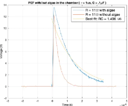
Fig. 20 shows the voltage measured across the potentiometer when the resistance is 11 Ω. Without algae present, the measured time constant is roughly 0.5us. This is to be expected since the additional resistance of the algae is not present. With algae and the chamber present, the measured time constant is approximately 1.25us. Using this value as the experimental value, and the measured time constant in simulation, 1.10us, as the accepted value, the percent error is 11.6%. This percent error is acceptable since the time constant is between 1us-2us.
FIGURE 20:1US WAVEFORM MEASURED ACROSS POTENTIOMETER WITH AND
19
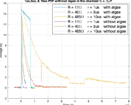
Fig.21 compares the expected 1us, 3us, and 10us time constant measurements taken with and without algae. The 10us response with algae appears to have a lot of noise. It is speculated that this noise occurs due to the connection cables between the electroporator system and the algae chamber. The 3us and 10us response without algae do not show a complete decaying waveform since the resistance of the algae is not present.
FIGURE 21: 1US,3US, AND 10US WAVEFORMS MEASURED ACROSS POTENTIOMETER WITH AND
20
High voltage testing with algae was taken at an expected time constant of 3us and a voltage range of 15V-140V for comparison, which is shown in Fig. 22. Most measured time constants from the data below fall within the 2us-3us range. These discrepancies are acceptable since we are hoping to achieve time constants in the 1us-10us range. The discrepancies in the R = 485 Ω may be due to inductance created by the amplifier, wires, or solder connections. More testing needs to be conducted on the discontinuities of the waveforms once in person meetings resume. Additional data can be viewed in Appendix A.
FIGURE 22:3US WAVEFORM MEASURED ACROSS POTENTIOMETER WITH AND
21
Solid State Relay Electroporator
The second pulse generator is constructed with two solid state relays (SSRs) controlled by an Arduino, Fig.23. The Arduino code determines the pulse widths and allows the injection of a train of pulses into the algae. The SSR configuration currently contains two problems. One of the bugs may originate from the predicted ITO + algae impedance model, Fig.9. This conclusion is based on the pulse shape characteristics obtained from modeling the ITO + algae impedance in the mechanical relay and calculating an algae resistance of about 126 Ω. The predicted model, shown in Fig.9, would assume an open circuit with DC voltage. The second bug creates an 80% voltage drop across the algae. The electrical team believes that the opto-TRIACs voltage drop and the ITO + algae impedance model causes this voltage drop. The BBM solution was disregarded as the cause of this discrepancy because tests were performed using different solutions to observe how the pulse characteristics change. The test included
centrifuging a culture of algae from the bottom of a centrifuge tube, extracting the BBM, re-submerging the algae in deionized water (less conductive that the BBM media solution), and injecting a PEF across the algae. These results concluded that the BBM solution does not alter the pulse shape.
FIGURE 23:SOLID STATE RELAY ELECTROPORATOR CIRCUIT DIAGRAM
TABLE 3
SOLID STATE ALGAE ELECTROPORATOR SSRTRUTH TABLE
Solid State Relay 1 Solid State Relay 2 Circuit State
ON OFF 1 Capacitor Charges
OFF OFF 2 Capacitor discharges into algae chamber OFF ON 3 SSR 2 discharges the capacitor
22
The Arduino (5 VDC) supplies the 13mA of input current to turn on the SSRs. The potentiometers control the optocoupler’s current. This current controls the light intensity that turns on the transistor and allows current to flow from U1 (SSR 1) pin 8 to pin 7. The logic states of SSR and SSR2 are defined in Table 3. The electroporator system can be seen in Fig. 24-25.
FIGURE 24:SOLID STATE RELAY ELECTROPORATOR COMPONENTS
23
Solid State Relay Electroporator Simulation
The SSR electroporator is simulated using LTSpice. The constructed circuit is in Fig. 26
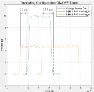
and Fig. 27. LTSpice does not have a SSR component so two switches are used to mimic the behavior of a relay. The switch 1 functions as SSR1 and switch 2 functions as SSR2 from Fig. 23. SSR2 is used to discharge the capacitor node to ground as observed on the right of Fig. 26. This truncation time determines the pulse width. If SSR2 truncates the capacitor node at a later time, the pulse width increases.
FIGURE 26:LTSPICE ALGAE ELECTROPORATOR SSRCONFIGURATION WITHOUT ALGAE SIMULATION
24
Solid State Electroporator Data
FIGURE 28A:SOLID STATE RELAY PULSE CHARACTERISTICS WITHOUT ALGAE CHAMBER
FIGURE 28B:SOLID STATE RELAY PULSE CHARACTERISTICS WITHOUT ALGAE CHAMBER
25
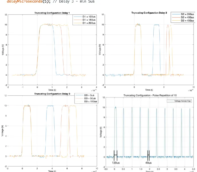
The following code respectively generates a minimum pulse width of about 30μs and a minimum period of 476μs. This code alters the pulse width and period with the help of 3 delay commands (Delay 1, 2, and 3). To generate a train of pulses the following code is ran in a loop.
Fig. 29 depicts how applying changes to the code alters the pulse shape characteristics. The full Arduino code and algae PEF treatment setup are in Appendix B.
FIGURE 29:SOLID STATE RELAY PULSES CREATED BY CHANGING DELAY TIMES
26
Bill of Materials: Parts List
TABLE 4
MECHANICAL RELAY ELECTROPORATOR AND SSRELECTROPORATOR PARTS LIST
Part Number Description Distributor Quantity Total Cost
495-4962-1-ND 1nF Capacitor Digi Key 10 $5.08
Unknown 1 kΩ Resistor - 2 $0.00*
Unknown 3 kΩ Resistor - 1 $0.00*
Unknown Mechanical Relay
- 1 $0.00*
Arduino Uno Micro Controller - 1 $0.00*
Z8463-ND Solid State Relay Digi Key 2 $18.82
Unknown Potentiometer - 2 $0.00*
3590S-2-103L Potentiometer Allied 1 $13.13
Total $37.03
27
Conclusion
When the research team can reassemble on campus, testing will continue with the mechanical electroporator system. The Biology team will determine if lysis has occurred. The next step of testing with the mechanical electroporator involves sending multiple pulses at least 1s apart to account for the 0.5s relay switching time. Measurements and photos will be taken to determine which voltage, time constant, and amount of pulses yields the best result for lysis of the algae cells.
Modifications may need to be added if it is determined lysis will be achieved by applying multiple pulses to the algae in a time span shorter than 1s. One suggestion to achieve multiple pulses is to introduce additional relays in parallel that can each be triggered separately. This will allow for multiple pulses to be sent into the algae sample to expose it to an electromagnetic field for a longer portion of time than 1us-10us, a possible schematic is depicted in Fig 30. Additional modifications that can be made is to change the value of the capacitor. Changing the capacitor value and using the respective potentiometer values in Table 2 will allow a wider range of testing.
FIGURE 30:PULSE TRAIN ELECTROPORATOR, MULTIPLE MECHANICAL RELAYS
Once testing has commenced on the mechanical relay electroporator and the team has concluded to have a working model, debugging the solid-state relay circuit will begin. The initial discrepancy the team will aim to solve will be the 80% decrease in voltage that is seen across the sample. The team will begin to debug and determine if the voltage measured across each
28
References
[1] “Methodology,” Lyse. [Online]. Available: https://lyse-it.com/pages/methodology. [Accessed: 10-May-2020].
[2] M. Schmitt, et al., “Portoporator: A portable low-cost electroporation device for gene transfer to cultured cells in biotechnology, biomedical research and education,” ScienceDirect,
Biosensors and Bioelectronics, 15-April-2019, vol. 131, pp 95-103. doi:10.1016/j.bios.2019.02.024. [Accessed: October 16th, 2019].
[3] S. Kar, et al., “Single-Cell electroporation: current trends, applications and future prospects,”
Journal of Micromechanics and Microengineering, vol. 28, Number 12, 31 October 2018. [Accessed: October 31st, 2019].
[4] L. Buchmann, et al., “Effect of nanosecond pulsed electric field treatment on cell
proliferation of microalgae,” ScienceDirect, Bioresource Technology, vol. 271, pp. 402-408, January 2019, doi:10.1016/j.biortech.2018.09.124. [Accessed: October 31st, 2019].
[5] L. Rems and D. Miklavcic, “Tutorial: Electroporation of cells in complex materials and tissue,” J. Appl. Phys., vol. 199, 201101(2016), 23 May 2016. doi:10.1063/1.4949264 [Accessed: October 16th, 2019].
[6] “RC Discharging Circuit Tutorial & RC Time Constant,” Basic Electronics Tutorials, 01- May-2020. [Online]. Available: https://www.electronics-
tutorials.ws/rc/rc_2.html?utm_referrer=https://www.google.com. [Accessed: 10-May-2020].
[7] “IEEE-SA - The National Electrical Safety Code® (NESC®),” IEEE-SA - The IEEE \ Standards Association - Home. [Online] [Accessed: 25-Feb-2019].
https://standards.ieee.org/products-services/nesc/index.html
[8] “Free online access to the NEC® and other electrical standards,” NFPA reports - Fires in the United States. [Online][Accessed: 25-Feb-2019].
29
Appendix A: Mechanical Relay Electroporator Data
Simulation
FIGURE 31:2US WAVEFORM MEASURED ACROSS THE SIMULATED ALGAE
30
FIGURE 33:4US WAVEFORM MEASURED ACROSS THE SIMULATED ALGAE
31
FIGURE 35:7US WAVEFORM MEASURED ACROSS THE SIMULATED ALGAE
32
FIGURE 37:9US WAVEFORM MEASURED ACROSS THE SIMULATED ALGAE
Hardware
33
FIGURE 39:LOW VOLTAGE3US WAVEFORM MEASURED ACROSS POTENTIOMETER WITH AND WITHOUT
ALGAE
FIGURE 40:LOW VOLTAGE10US WAVEFORM MEASURED ACROSS POTENTIOMETER WITH AND WITHOUT
34
Appendix B: PEF Treatment Set Up Instructions
PEF Treatment Instructions
A PEF treatment is created by clamping the two ITO conductive plates, shown in Figure 34, parallel to each other. The two conductive faces of the ITO glass slides must face one
another.
FIGURE 41:ITO PEF Treatment Chamber
• With a pipet, place a 0.5mL sample of algae on one side of the chamber and allow capillary action to draw the algae into the chamber.
• Place the ITO PEF chamber under a microscope and locate the algae for viewing
• Connect the cables soldered to the ITO glasses across the capacitor
• Mechanical Relay Electroporator - Figure 14 • Solid State Relay Electroporator - Figure 24
• For the SSR configuration utilize the following Arduino code to create the desired pulse characteristics
• Delay 1 – Controls Pulse Width (Figure 29)
• Delay 2 – Controls Pulse Period (Figure 29)
• Delay 3 – Controls Pulse Period (Figure 29)
In the setup, a DC voltage supply feeds a DC voltage amplifier providing 80V-140V to the electroporator, Figure 11. Setting the horizontal time scale on an oscilloscope to 1ms per division and enabling the trigger function will capture the pulse when probed across the capacitor, Figures 14 and Figure 24.
Note(s) :
Record data, capture waveforms, and analyze the circuit through an oscilloscope procedure:
• Temporarily disconnect the ITO PEF (Indium Tin Oxide Pulsed Electric Field) chamber
• Command the Arduino to output an infinite pulse train through a loop function
• Running an infinite pulse train makes it easy to auto scale, set voltage triggers, etc.
• Set the oscilloscope functions as appropriate and command the Arduino to stop
35
36
Appendix C: Senior Project Analysis
Project Title: Pulsed Electric Field System Development for Algae Biofuel Extraction
Student’s Name(s): Aspyn Bessler and Juan David Gonzalez Aguayo
Student’s Signature(s):
Advisor’s Name(s): Professor Dean Arakaki
Advisor’s Signature(s):
The following is holistic analysis that describes the effects, costs, and benefits associated to the manufacturing of the described algae electroporators.
1. Summary of Functional Requirements
The described algae electroporators are designed to administer an electrical pulse to algae cells to attempt irreversible pore formation to extract the cell’s lipids.
• The mechanical relay electroporator circuit design contains relays, capacitors, and resistors to outputs PEFs between 1µs to 10µs. The user can select the pulse duration by changing the value of the potentiometer. The system utilizes a relay to switch and discharge a capacitor to the algae sample, creating a pulse electromagnetic field.
• The solid state electroporator circuit design contains solid state relays, an Arduino, a capacitor, and potentiometers to output PEFs up to a 30μs pulse width and a period of up to 476μs. This electroporator turns on one of the SSRs to create a voltage potential across the algae and discharges this voltage potential when the code commands. The Arduino enables controllable pulse widths, periods, and cycles of repetition.
2. Primary Constraints
Delivering PEFs with variable characteristics is the main constraint of this project. These constraints are critical because they limit PEF widths, duty-cycles, period, amplitude, and cycle repetition. A broad range of output PEF characteristics is important to research the attributes that cause membrane rupture. The biggest limiting factor is a pulse shape alteration when algae is introduced into the chamber. The algae itself is believed to cause this pulse mutation as our equivalent circuit model is not 100% accurate.
• The mechanical relay electroporator limiting factors include:
o The relays time delay between successive repetitions (~500ms)
o Exclusive discharging capacitor pulse shape
• The solid state electroporator limiting factors include:
o SSRs turn ON/OFF times constrain the pulse width to no less than 30μs
37
3. Economic
Fixed production costs are minimized as much as possible to reflect a donation given by Boeing. The student project budget does not include human, real, natural, and external costs as they require individual analysis. Table 4 depicts a cost breakdown estimate for the production of one electroporator device.
The cost analysis described contains approximate values to produce one system. The total cost to manufacture and maintain the described algae explicit electroporator depends mostly on its development, forecasted production, and expected device usage.
Note that development and production costs carry less approximation error due to their nature but, device usage costs depend on the device expected usage and reliability. The electroporator requires electrical energy (from a commercial power source), a PEF chamber, algae and BBM, and a way to check lysis for its intended usage.
• The human capital constitutes student researchers and project advisors. Externalities such as outsourced manufacturing and component acquisition might also require human capital but are not considered due to their nature.
• The financial capital includes test equipment, facility expenses, software licensing, outsourced published scientific literature, algae cultivation materials, prototype construction, and device production.
• The real capital illustrates a fraction of the human capital costs because this analysis describes an electroporator constructed manually.
38
4. If Manufactured on a Commercial Basis
The cost analysis disregards both electroporator and biofuel mass-production, and instead derives an approximated analysis based exclusively from manufacturing one device. Electroporator mass-production and market values are approximated and analyzed utilizing Table 4.
• Estimated number of devices sold per year: 20
• Estimated manufacturing cost for each device: $250
• Estimated purchase price for each device: $600
• Estimated profit per year: $7,000
5. Environmental
The project harms algae in the process. The project entails irreversible pore formation of algae to release their stored lipids for collection. Environmental impacts occur when parts of the device are not recycled with care at the end of the electroporator’s lifetime.
Electroporator mass-production breakdown:
Positive:
• Electroporators with different characteristics already exist. One can take the environmental impacts associated with their manufacturing and minimize algae electroporator impacts.
Negative:
• Production requires electrical energy obtained from non-sustainable sources
• Facility requires real estate, construction elements, equipment, and maintenance
• Electroporator requires outsourced components
• Electroporator requires proper disposal after its lifetime
• A fraction of the components required for its construction are not environmentally friendly
6. Manufacturability
39
7. Sustainability
The goal of the project depicts creating a device that can administer PEF treatments to algae samples. The electroporator must assist in the processes of creating renewable fuel. The hope is that the algae samples absorb the amount of CO2 during their growth period to cancel out the
CO2 released into the atmosphere when the biofuel created is used. The electroporator demands
electrical energy (from a commercial power source), a PEF chamber, and algae with BBM for its intended usage. It also demands additional facility electrical energy usage and real estate
demands when device is mass-produced. Technological, production, and sustainable advancements lead to positive improvements. Additional social and socio-economic improvements appear when the device emerges for consumer usage.
The sustainable practices proceeding the designing of this device follow:
Environmental
• Minimize energy consumed by electroporation
o Energy efficient switching, and display circuitry
o Reduction of components
• Salvaged electrical components
Economical
• Cut monetary resources
o Salvaged electrical components
• Utilized Cal Poly SLO Resources
o Library
o Software
o Laboratories
Social
40
8. Ethical
TABLE5(PART1):BREAKDOWN OF ETHICAL IMPLICATIONS PROCEEDING ALGAE ELECTROPORATION
TREATMENT AND ALGAE ELECTROPORATOR DEVICES
Ethical Concerns (Stages of Implication)
Ethical Analysis Framework
Justification &/or Notes
Algae are living organisms and this
device explains a treatment that kills the
algae (Design, Operating, and Developmental Stages) Egoism
Algae cell biofuel production promises economical and power acquisition. All
organisms directly or indirectly affected when researching must be considered when designing and operating electroporators. The average algae (depending on species) only survive for a few days to two years. The lysing of the algae premature to natural cell death will not drastically alter the lifespan of the living organism.
IEEE
This device kills the algae cell whereas other electroporation treatments usually disturb the living organisms. The lifespan of the living organisms requires consideration and study. Apoptosis, or cell death, means that biofuel components are deteriorating but, to obtain adequate intracellular components they need to bed accessed early in the algae lifespan.
Production whether large or small scale can
cause negative ecological footprints (Manufacturing, Operating, and Developmental Stages) Contractarianism
Rhetorical issues manifest when the message is not clearly defined for its intention. Large scale production of the electroporator or biofuel will cause impacts which are briefly discussed throughout Appendix A. The negative and positive ecological impacts of a unit are discussed in the environmental subsection.
IEEE
41
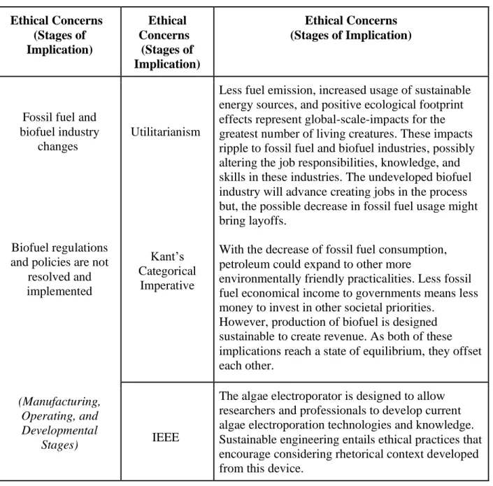
TABLE5(PART 2):BREAKDOWN OF ETHICAL IMPLICATIONS PROCEEDING ALGAE ELECTROPORATION
TREATMENT AND ALGAE ELECTROPORATOR DEVICES
Ethical Concerns (Stages of Implication) Ethical Concerns (Stages of Implication) Ethical Concerns (Stages of Implication)
Fossil fuel and biofuel industry
changes
Biofuel regulations and policies are not
resolved and implemented (Manufacturing, Operating, and Developmental Stages) Utilitarianism Kant’s Categorical Imperative
Less fuel emission, increased usage of sustainable energy sources, and positive ecological footprint effects represent global-scale-impacts for the greatest number of living creatures. These impacts ripple to fossil fuel and biofuel industries, possibly altering the job responsibilities, knowledge, and skills in these industries. The undeveloped biofuel industry will advance creating jobs in the process but, the possible decrease in fossil fuel usage might bring layoffs.
With the decrease of fossil fuel consumption, petroleum could expand to other more
environmentally friendly practicalities. Less fossil fuel economical income to governments means less money to invest in other societal priorities.
However, production of biofuel is designed sustainable to create revenue. As both of these implications reach a state of equilibrium, they offset each other.
IEEE
9. Health and Safety
Development:
The development process (manual construction and testing) implicates following standard high-voltage laboratory safety procedures. [7] [8]
Usage:
The electroporator requires a commercially available power source using 120 VAC from a
US wall socket. Enclosing the electrical elements and placing the algae away from the user is the safest way to operate the machine.
Production:
Large scale production of algae electroporators and algae biofuel projects a small deviation of health and safety concerns from those present in current electroporator manufacturing, algae cultivation methods, and biofuel production. [7] [8]
10. Social and Political
The direct and indirect stakeholders are algae and researchers. The project benefits researchers to help them further understand the process and develop techniques for extracting lipids from an algae sample.
Less fuel emission increase usage of sustainable energy sources and positive ecological footprint impacts depict global scale social and political impacts. Proving governments and every living creature as an indirect stakeholder when presenting large scale usage. Political issues arise if the project progresses to mass and consumer level production.
11. Development