Rate Regions for Coordination of
Decode-and-Forward Relays and Direct Users
Chan Dai Truyen Thai and Petar Popovski
Department of Electronic Systems, Aalborg University
Email:
{
ttc, [email protected]
}
Abstract—Recently, the ideas of wireless network coding (NC) has significantly enriched the area of wireless coopera-tion/relaying. They bring substantial gains in spectral efficiency mainly in scenarios with two–way relaying. Inspired by the ideas of wireless NC, recently we have proposed techniques for coordinated direct/relay (CDR) transmissions. Leveraging on the fact that the interference can be subsequently canceled, these techniques embrace the interference among the communication flows to/from direct and relayed users. Hence, by allowing simultaneous transmissions, spectral efficiency is increased. In our prior work, we have proposed CDR with Decode–and– Forward (DF) relay in two scenarios. In this paper, we extend the two existing regenerative CDR schemes and proposed for the other two scenarios such that all schemes benefit from the aforementioned principle of containing the interference. The parameters in the schemes are optimized to have the largest rate region or the highest sum-rate. Numerical results show that DF CDR is better than the reference scheme and almost better than AF CDR.
Index Terms—Cooperative communications, relaying, analog network coding, interference cancelation, a priori information.
I. INTRODUCTION
Recently there have been extensive studies on cooperative, relay–based transmission schemes for extending cellular cover-age or increasing diversity. Several basic relaying transmission techniques have been introduced, such as amplify-and-forward (AF) [1], decode-and-forward (DF) [2] and compress-and-forward (CF) [3]. These transmission techniques have been applied in one-, two- or multi-way relaying scenarios.
In particular, two–way relaying scenarios [4], [5], [6] have attracted a lot of attention, since it has been demonstrated that in these scenarios one can apply techniques based on NC in order to obtain a significant throughput gain. There are two basic principles used in designing throughput–efficient schemes with wireless NC (1) aggregation of communication flows- NC operates by having the flows sent/processed jointly; (2) intentional cancelable interference: flows are allowed to interfere over the wireless channel, knowing a priorithat the interference can be cancelled by the destination.
Using these insights, in [7] we have proposed schemes, depicted on Figs. 1 and 2 for traffic scenarios that are more general than the usual two–way relaying. These schemes are termed coordinated direct/relay (CDR) transmissions. In the scheme on Fig. 1, termedS1, U receives downlink traffic from the BS, while V sends uplink traffic to the BS. For the scheme
S1, in the first step the BS transmits to the relay RS. In the second step, RS transmits to U and simultaneously V transmits
to the BS. The reception of V’s signal at BS is interfered by the transmission of RS; however, since BS knows the signal of RS a priori, it can cancel it and get a “clean” message from V. Enabling such simultaneous transmissions improves the spectral efficiency. In schemeS2, in the first step BS sends
to V and simultaneously U sends to RS, such that RS receives interference of these two signals, such as in analog NC for two–way relaying. But, unlike two–way relaying, the signal sent by RS in the second step need only be decoded at BS, but not at U. This makes the link RS-U irrelevant and, as we will see later, deflecting the traffic to go V instead of BS-RS-U, and combining it with the traffic U-RS-BS, can give advantages in the sum–rate.
Transmission schemes that are related to some of the schemes proposed in this paper have appeared before in the literature [8], [9], or to relayed users [10]. We have considered RS that uses Amplify-and-Forward (AF) in [11] and proposed two schemes of Decode-and-Forward (DF) for two CDR scenarios in [12]. In this paper we extend the two existing schemes and proposed DF CDR schemes for the other two CDR scenarios such that in all schemes, a station uses the information about the interference to cancel it and decode the desired signal. The choice of the duration of different phases in the schemes S1,S2,S3 and S4 is subject to optimization. The optimization objective is the rate region and the sum–rate for each of the respective schemes.
The rest of the paper is organized as follows. Section II introduces the system model. The DF reference and CDR schemes are described in section III. Section IV shows and discusses some numerical results. Section V concludes the paper.
II. SYSTEMMODEL
We consider a scenario with one base station (BS), one relay (RS), and two users (U and V), see Fig. 1. All transmissions have a unit power and normalized bandwidth of 1 Hz. Each of the complex channelshi, i∈ {1,2,3,4}, is reciprocal, known
at the receiver. All the channels are known at BS.
In the scenario, BS sends messages s1 to U and s4 to V and receives messagess3from U ands2from V. Note that the example on Fig. 1 does not show traffic patterns that involve
BS
RS
x2,2
(2- max(µ, λ))N
V U
µN
x1 x2,1
R 2 , 1 x
R 1 , 1 x
x1 (2 -λ)N
λ N
DF Ref x
2 R
1 x
h1
h3 h2
h4
2 , 2 x
x1
DF CDR µ ≥λ
x2,1= x2
λN R
1 , 1 x
x1
(2- max(µ, λ))N
µN
DF CDR µ < λ
x2,1
R 2 , 1 x
R 1 R
1 ,
1 x
x =
λN
Fig. 1. Reference and CDRS1Schemes. The time slot of the transmission represented by an arrow above is represented by a rectangular below with the same color and dash style. The transmissions represented by the rectan-gles in the same column are conducted simultaneously. The interference is represented by an arrow with a thicker head.
into sub-messages si,1 andsi,2. If message si,si,1 or si,2 is
sent from BS, U or V, it is encoded to symbol string xi,xi,1
or xi,2 respectively. If it is sent from RS we have the symbol
string xR
i, xRi,1 or xRi,2 respectively. Denoting |s| and |x| as
the number of bits and number of symbols of messagesand symbol string x respectively, we have |si| = |si,1|+|si,2|
and |xi| = |xi,1|+|xi,2|. Because there are many cases of
channels are considered, we combine some similar cases and describe the schemes in the combined one. Therefore, if si,2
andxi,2are not mentioned in a scheme, it means that|si,2|=
0,|xi,2|= 0 andsi,1=si,xi,1=xi.
The direct channel BS–U is assumed weak and U gets the information from BS only through the decoded/forwarded signal from RS. If in slot k, the reception of x at node m
is additionally interfered by w, then the received signal is
ym[k] =hix+hjw+zm[k], k ∈ {1,2,3}, m∈ {B, R, U, V}
wherezm[k]∼ CN(0, σ2)is Additive White Gaussian Noise
(AWGN). Denoting the capacity function asC(γ) = log2(1 +
γ), we can write the capacity of such a transmission as
Ci−j = C
|h
i|2
|hj|2+σ2
= C gi
gj+1
with gi = |hi|
2
σ2 . In case
there is no interfering signal the capacity isCi= log2(1 +gi).
If the receiver jointly decodes x and w, the maximal sum rate for these two signals is Cij = log2(1 +gi+gj). It is
straightforward to see thatCij =Cji, Cij =Cj+Ci−j.
In each scheme, the total time length is 2N symbols. Ri U
andRi
V, i∈ {E, S1, S2, S3, S4}are maximal rates for U and
V respectively in scheme i.E denotes the reference scheme, all schemes will be described in the next part. The sum–rate is therefore estimated asRiS =RiU+RiV =21N(DiU+DiV),
where DiU, DiV represent the corresponding number of bits. The transmission for the direct user has a duration of λN
symbols. In the following part, we analyze the choice of λ
with respect to the optimization of the sum–rate.
III. REFERENCE ANDCDR SCHEMES
CDR scheme 1 denoted as S1 delivers two messages s1
and s2. CDR schemes S2, S3 and S4 deliver messages pairs(s3, s4),(s1, s4)and(s2, s3)respectively. CDR schemes combine the transmissions of the two messages in such a way that the information about the interference is exploited as much as possible while reference schemes use orthogonal transmissions by multiplexing them in time. However, since the transmit power of all nodes are the same and all channels are reciprocal, 4 reference schemes which are corresponding to 4 CDR schemes have the same rates.
A. Reference Scheme
First, BS encodes s1 to x1 with rate R1 and transmits it
to RS yR[1] =h1x1+zR[1]. Second, RS decodes x1 tos1,
re-encodes it to xR
1 with rate RR1 and transmits it to U (see
Fig. 1) yU[2] = h2xR1 +zU[2]. Third, V encodes s2 to x2
with rate R2 and transmits it to BS yB[3] =h3x2+zB[3].
Since the V–BS transmission’s length is pre-defined as λN
symbols and all transmissions are performed separately, the total time length for U is therefore (2−λ)N. We denote the number of symbols in the RS–U transmission asµN. The rates
R1, RR1 and R2 are selected as the maximal rates over the corresponding channels R1 =C1,RR1 =C2 and R2 =C3.
The maximal data sent through the BS–RS, RS–U and V– BS transmissions are respectively DE
U1 = (2−λ−µ)N C1, DUE2 =µN C2, DEV =λN C3. The total data transmitted for two users is DE
S = min(DEU1, D
E U2) +D
E
V. Since DVE does
not depend on µ, DE
U1 is a decreasing function and D
E U2 is
an increasing function ofµ, in order to get maximal DE S, µ
is selected such that DE U1 = D
E
U2. Solving this equation we
have the optimalµ=µE opt=
(2−λ)C1
C1+C2 . The data for U and V
are respectively DUE = (2−λ)N C1C2
C1+C2, D
E
V =λN C3.The
sum–rate isRES =(2−λ)C1C2 2(C1+C2) +
λN C3 2 .
B. CDR Scheme 1
First, BS transmitsx1 to RS (see Fig. 1) yR[1] = h1x1+ zR[1]. Second, RS decodes x1 tos1, divides it into two
sub-messages, re-encodes them to xR
1,1, xR1,2 and transmits xR1,1
to U. In the meantime and similarly, V transmitsx2,1 to BS yB[2] =h2xR1,1+h3x2,1+zB[2],yU[2] =h1xR1,1+h4x2,1+ zU[2]. Third, ifµ ≥λ, RS transmitsxR1,2 to U
interference-freeyU[3] =h1xR1,2+zR[3]. Ifµ < λ, V transmitsx2,2to BS
interference-freeyB[3] =h3x2,2+zB[3].
The total length of the transmissions for the direct user, which is the V–BS transmissions here, is pre-defined as λN
symbols. Denote the number of symbols in the RS–U trans-missions asµN. Since BS and RS cannot transmit and receive at the same time, the BS–RS transmission cannot be performed simultaneously with any other transmission. Because the RS– U and V–BS transmissions do not completely coincide, the length of the BS–RS transmission is thus determined as (2−max(µ, λ))N symbols. Therefore, the messages s1 and s2are divided and encoded at RS and V respectively such that
|x1,1|=|x2,1|= min(µ, λ)N. Ifµ≥λ,|xR1,1|=|x2,1|=|x2|
and |xR
O8
O7
(a)
R RV
C1
RU+RV = C12
(b)
(c)
O
C1-2 C3-4
O3
O2
O1
O4
O6
O5
RU
C2
O
C2-1
Fig. 3. Rate regions of(RU, RV)ofS2in slot 1.
|x2,2| = λ−µ. In the following, we estimate the optimal
value of µ for a pre-defined value of λ. Since BS knows x1
and therefore xR1,1 andxR1,2 thus BS cancels the contribution of x1 in the received signal. The total data sent through the BS–RS, RS–U and V–BS transmissions are respectively
DS1
U1 = (2−max(µ, λ))N C1, D
S1
U2 = min(µ, λ)N C2−4+
(µ−min(µ, λ))N C2, DSV1 = λN C3. The sum–rate of two
users is RS1
S = DS1
S
2N =
min(DS1
U1,D
S1
U2)+D
S1
V
2N .
C. CDR Scheme 2
First, U transmitsx3,1with rateRU to RS and BS transmits x4,1 with rate RU in min(µ, λ)N symbols simultaneously yR[1] =h2x3,1+h1x4,1+zR[1],yV[1] =h4x3,1+h3x4,1+ zV[1]. Second, U transmitsx3,2 to RSyR[2] =h2x3,2+zR[2]
or BS transmits x4,2 to V yV[2] = h3x4,2 + zV[2] in
|µ−λ|N symbols interference-free with maximal rates of the corresponding channelsC2 andC3 respectively (see Fig. 2a).
Third, RS decodes x3,1 and x3,2, re-encodes and forwards
them to BS yB[3] = h1xR3 +zB[3] with the maximal
in-stantaneous rate C1. Since BS and RS cannot transmit and receive at the same time, the RS–BS transmission cannot be performed simultaneously with any other transmission, it starts only after the first max(µ, λ)N symbols are finished. Thus
|xR
3|=|xR3,1|+|xR3,2|= (2−max(µ, λ))N. We consider two
cases:
• C1> C5: Since in the third time slot, RS transmits with
rateC1, V cannot decode this information.RU andRV in
the first time slot are thus selected such that V can decode
x4 treatingx3 as noise RV ≤C3−4 and RS can decode x3. There are two cases to satisfy the second condition:
– RS decodesx3treatingx4 as noise:RU ≤C2−1. – RS decodes both x3 and x4 according to Multiple
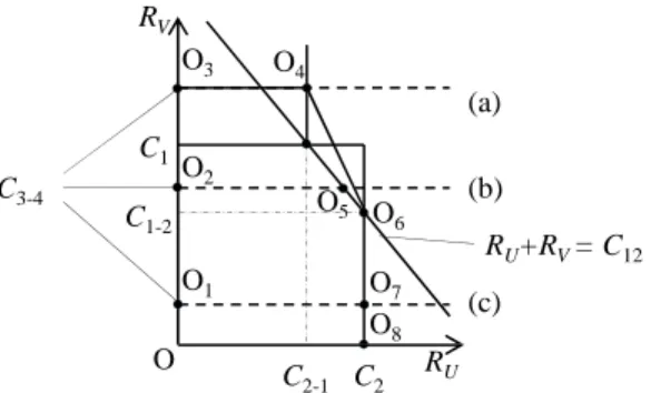
Access Channel (MAC) [14]: RU ≤C2,RV ≤C1, RU +RV ≤C1,2.
Fig. 3 demonstrates the rate region of(RU, RV), the rates
selected in slot 1. Depending on the value of C3−4 we
have the region with different shapes: (a) OO3O4O6O8
if C3−4≥C1, (b) OO2O5O6O8 ifC1−2≥C3−4< C1,
(c)OO1O7O8 ifC3−4< C1−2.
• C1 ≤ C5: Since in the third time slot, RS transmits with rate C1, both BS and V can decodexR3. Using the
information about s3, the interference in the first slot at V can be completely canceled. Therefore in the first slot BS can transmitx4to V with the maximal rateRV ≤C3.
(a) (b) (c)
RV
C3
C
RU+RV = C3,5
O
C2
RU
C5 C5-3 C3-5
Fig. 4. Rate regions of(RU, RV)ofS3in slot 2.
We have the same conditions as in the ofC1< C5, the only difference is thatC3−4 is replaced byC3. We have
the same rate region of(RU, RV), the rates selected in
slot 1, as in Fig. 3 whereC3−4 is replaced byC3.
The data transmitted in U–RS, RS–BS, BS–V transmis-sions and the total data transmitted to two users are re-spectively DS2
U1 = min(µ, λ)RUN + (µ−min(µ, λ))C2N, DS2
U2 = (2−max(µ, λ))C1N,D
S2
V = min(µ, λ)RVN+ (λ−
min(µ, λ))C3N andDSS2 = min(D S2
U1, D
S2
U2)+D
S2
V . The
sum-rate isRS2
S = DS2
S
2N .
Above we consider the cases when V has to decode at least
s3 or s4 in slots 1 and 2 or in slot 3. The case when V does not need to decode any of them can be achieved by using combining two replicas of the information sent originally by U, each encoded with a different codebook (one used by U and the other by RS). However, such a scheme is outside the scope of this paper.
D. CDR Scheme 3
The transmissions are conducted in the following steps (Fig. 2b): First, BS transmitsx1to RS in(2−max(µ, λ))N symbols
yR[1] = h1x1+zR[1] with maximal instantaneous rate C1.
Second, RS and BS transmits xR
1,1 with rate RU and x4,1
with rateRV respectively and simultaneously inmin(µ, λ)N
symbolsyU[2] =h2xR1,1+zU[2],yV[2] =h5xR1,1+h3x4,1+ zV[2]. Third, RS transmitsxR1,2in(µ−λ)N symbolsyU[3] = h2xR1,2+zU[3]if µ≥λand BS transmitsx4,2 in(λ−µ)N
symbolsyV[3] =h5xR1,2+h3x4,2+zV[3]ifµ < λ. Note that
when µ ≥ λ, |x4,2| = 0 and x4,1 = x4 and when µ < λ,
|x1,2| = 0 and x1R,1 = xR1. Similar to S2, we consider two
cases:
• C1 > C3: Since BS transmits with rate C1 in the first time slot, V cannot decode the information.RU andRV
in the second time slot are thus selected such that U can decode x1,1 (RU ≤C2, since the BS-U channel is zero)
and V can decodex4,1. There are two cases to satisfy the
second condition:
– V decodesx4,1 treatingxR1,1 as noise:RV ≤C3−5. – V decodes bothxR1,1 andx4,1:RU ≤C5,RV ≤C3,
BS
RS
x2,2
(2- max(µ, λ))N V U
µN x3,1
x2,1= x2
λN x3,1
x2,1
(2- max(µ, λ))N x3,2
R 1
x
R 3
x
x3,2 h3
h1
h2
h5
BS
RS
x4,2
x1
(2- max(µ, λ))N
V U
µN
x4= x4,1
λN
x1 x4,1
R 2 , 1
x
R 1 , 1
x
(2- max(µ, λ))N
R 2 , 1
x
R 1 , 1
x
h1 h
3
h5
h2
BS
RS
x4,2
(2- max(µ, λ))N V U
µN
DF CDR µ ≥λ x
3,1
x4,1= x4
λN x3,1
x4,1
(2- max(µ, λ))N x3,2
R 3
x
R 3
x
x3,2 h3
h1
h2
h4
2 , 2
x
(2- max(µ, λ))N µN
x3,1 = x3
x2,1
λN
R 3
x
2 , 4
x
x1
(2- max(µ, λ))N µN
x4,1
λN R 1 R
1 , 1 x
x =
2 , 4
x
(2- max(µ, λ))N µN
DF CDR µ < λ x
3,1= x3
x4,1
λN
R 3
x
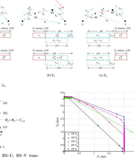
(a) S2 (b) S3 (c) S4
Fig. 2. Time slots in CDR SchemeS2,S3 andS4.
O7
O6 (a)
R RV
C5
RU+RV = C2,5
(b)
(c)
O
C5-2 C3
O1
O2
O3 O4
O5
RU C2
O
C2-5
Fig. 5. Rate regions of(RU, RV)ofS4in slot 1.
The data transmitted in BS–RS, RS–U, BS–V trans-missions and the total data transmitted for two users are respectively DS3
U1 = (2 − max(µ, λ))C1N, DS3
U2 = (µ−min(µ, λ))C2N + min(µ, λ)RUN,D
S3
V =
(λ − min(µ, λ))C3N + min(µ, λ)RVN and DSS3 =
min(DS3
U1, D
S3
U2) +D
S3
V . Similarly to Scheme 2, Fig. 4
demonstrates the rate region of(RU, RV). It has different
shapes corresponding to different values of C2.
• C1 ≤ C3: Since BS transmits with rate C1 in the first
time slot, RS and V can decodex1. Using the information
abouts1, the interference in slot 2 at V can be completely canceled. Therefore in slot 2, BS can transmitx4,1 to V
with the maximal rate RV =C3 while RS can transmit x1,1 to U with the maximal rate RU = C2. The data
transmitted in RS–U, BS–V transmissions are different from the previous case DS3
U2 =µC2N,D
S3
V =λC3N.
The sum-rate of S3 is RS3
S = DS3
S
2N . Again combing two
symbol string with different codebooks can be used here at V to decode its desired signal.
E. CDR Scheme 4
The transmissions are conducted in the following steps (Fig. 2c): First, U and V transmits x3,1 with rate RU
and x2,1 with rate RV respectively and simultaneously in
min(µ, λ)N symbols yR[1] = h2x3,1 + h5x2,1 + zR[1], yB[1] =h3x2,1+zB[1]. Second, U transmitsx3,2in(µ−λ)N
symbolsyR[2] =h2x3,2+zR[2]ifµ≥λand V transmitsx2,2
0 0.5 1 1.5 2 2.5
0 0.5 1 1.5 2 2.5 3 3.5 4 4.5
Ri
U (bps)
R
i (V
b
p
s
)
DF-S1
DF-S2
DF-S3
DF-S4
DF-E
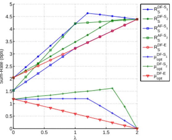
Fig. 6. Rate region of Ri U, RiV
(i∈ {S1, ..., S4, E}) for DF CDR and reference schemes.
in(λ−µ)NsymbolsyB[2] =h3x2,2+zB[1]ifµ < λsymbols.
Third, RS transmitsxR3 to BS in (2−max(µ, λ))N symbols yB[3] =h1xR3 +zB[3]. Note that whenµ≥λ,|x2,2|= 0and x2,1=x2 and when µ < λ,|x3,2|= 0 andx3,1=x3.
RU and RV are selected such that BS can decode x2,1
(RV ≤C3, since the U-BS channel is zero) and RS can decode x3,1. There are two cases to satisfy the second condition:
• RS decodesx3,1 treatingx2,1 as noise:RU ≤C2−5. • RS decodes both x3,1 and x2,1: RU ≤ C2, RV ≤C5,
RU +RV ≤C2,5.
The rate region of (RU, RV) is demonstrated in Fig. 5.
We have DS4
U1 = min(µ, λ)RUN + (µ−min(µ, λ))C2N, DS4
U2 = (2−max(µ, λ))C1N,D
S4
V = min(µ, λ)RVN+ (λ−
min(µ, λ))C3N andDS4
S = min(D S4
U1, D
S4
U2)+D
S4
V .The
sum-rate ofS4 is RS4
S = DS4
S
2N .
IV. NUMERICALRESULTS
0 0.5 1 1.5 2 0
0.5 1 1.5 2 2.5 3 3.5 4 4.5 5
λ
S
u
m
-R
a
te
(
b
p
s
)
RDF-S1
S RDF-S2
S RAF-S1
S RAF-S2
S RDF-E
S µDF-S1
opt µDF-S
2
opt µDF-E
opt
Fig. 7. Sum-rate and optimalµfor CDR Scheme 1 and 2 and reference scheme. Note thatµhas a different unit.
0 0.5 1 1.5 2
0 0.5 1 1.5 2 2.5 3 3.5 4 4.5
λ
S
u
m
-R
a
te
(
b
p
s
)
RDF-S3
S RDF-S4
S RAF-S3
S RAF-S4
S RDF-E
S µDF-S3
opt µDF-S4
opt µDF-E
opt
Fig. 8. Sum-rate and optimalµfor CDR Scheme 3 and 4 and reference scheme. Note thatµhas a different unit.
achieved by calculating the rate pair(Ri
U, RiV)for all values
ofλ,µandRU,RV which are selected such that satisfying the
conditions in each scheme with resolution ∆λ= ∆µ = 0.1 and ∆RU = ∆RV = 0.2. The reference scheme has the
most contained rate region since it does not exploit the information about the interference as all of the CDR schemes do. CDR scheme 1 has best rate region (high RV and not
low RU) because the only limiting factor in this scheme is
the interference from V to U over the inter-user channel, however, this channel is chosen as low (-10dB). Actually, this assumption is viable because in a cellular network with relays, the channel between two users is normally lower than the channel between a user and a infrastructure station (RS, BS) or the channel between two infrastructure stations (they are designed in good positions). Moreover, relayed users certainly appear in the region, which is covered by the RSs, far from the region where the direct users appear which is cover by the BS.
Fig. 7 and 8 show sum-rate of DF and AF CDR scheme 1, 2, 3, 4 and reference DF scheme whenλvaries. The channels are selected as in the previous simulation. With a specific value of
λ,µ,RU andRV are selected such that the sum-rate achieve
the maximal value. All schemes achieve a higher sum-rate when λ >1 and goes to 2 because the time resource is given to a direct transmission is more efficient than to a relayed transmission. Most of the schemes have a non-decreasing sum-rate with λ. Only DF CDR scheme 1 achieve the maximal
value whenλ <2. This is because this scheme well exploit the information of the interference as explained above. Most of DF CDR schemes are always better than AF CDR schemes except that DF CDR scheme 2 is worse than AF CDR scheme 2 when
λis medium. This is because all the interference received in AF CDR schemes is used to decode the desired signal using MMSE while in DF CDR scheme 2, RS has to receive the desired signal and the interference using MAC which limits the two rates.
V. CONCLUSION
In this paper, we propose and analyze the Coordinated transmissions to Direct and Relayed user in a wireless cellular network with relays using Decode-and-Forward. The durations of the transmissions for the direct and relayed users as well as the rates of simultaneous transmissions are optimized to have the best rate region and the maximal sum-rate. We compare the quality of the proposed schemes with their version of Amplify-and-Forward as well as the conventional scheme. Numerical results show that the proposed schemes almost provide better rates and sum-rate than the AF and reference schemes.
ACKNOWLEDGMENT
This work is supported by the Danish Research Council for Technology and Production, grant nr.09−065035.
REFERENCES
[1] G. Farhadi and N. C. Beaulieu, “Capacity of amplify-and-forward multi-hop relaying systems under adaptive transmission,” IEEE Trans. on Comm., vol 58, iss. 3, pp 758-763, 2010.
[2] Y. Zhu, P.-Y. Kam, and Y. Xin, “Differential modulation for decode-and-forward multiple relay systems,” IEEE Trans. on Comm., vol 58, iss. 1, pp. 189-199, 2010.
[3] Z. Liu, M. Uppal, V. Stankovic, and Z. Xiong, “Compress-Forward Coding With BPSK Modulation for the Half-Duplex Gaussian Relay Channel,” IEEE Trans. on Signal Processing, vol. 57, iss. 11, pp. 4467 -4481, 2009.
[4] P. Popovski and H. Yomo, “Bi-directional Amplification of Throughput in a Wireless Multi–Hop Network,” IEEE VTC, Spring 2006.
[5] S. Katti, S. Gollakota, and D. Katabi “Embracing Wireless Interference: Analog Network Coding,” ACM SIGCOMM, 2007.
[6] H. Ning, C. Ling, and K. K. Leung, “Wireless Network Coding with Imperfect Overhearing,” arXiv:1003.4270v1 [cs.IT] 22 Mar 2010. [7] C. Thai and P. Popovski, “Coordinated Direct and Relay Transmission
with Interference Cancelation in Wireless Systems,” IEEE Comm. Letters, vol. 15, no. 4, April 2011, pp. 416-418
[8] B. Bandemer, Q. Li, X. E. Lin, and A. Paulraj, “Overhearing-based Interference Cancellation for Relay Networks,” IEEE VTC, Fall 2009. [9] H. Yomo and E. de Carvalho, “Spectral Efficiency Enhancement with
Interference Cancellation for Wireless Relay Network,” IEEE PIMRC, Fall 2009.
[10] W. Chen, K. B. Letaief, and Z. Cao, “Network Interference Cancella-tion,” IEEE Trans. on Wireless Communications, vol. 8, iss. 12, pp. 5982 - 5999, Dec 2009.
[11] C. Thai, P. Popovski, M. Kaneko and E. Carvalho, “Coordinated Transmissions to Direct and Relayed Users in Wireless Cellular Systems,” in Proc. IEEE ICC, Kyoto, Japan, Jun 2011.
[12] C. Thai and P. Popovski, “Coordination of Regenerative Relays and Direct Users in Wireless Cellular Networks,” to appera in Proc. IEEE ISWCS’11, Aachen, Germany, Nov 2011.
[13] H. Cho and J. Andrews, “Resource-redistributive opportunistic schedul-ing for wireless systems,” IEEE Trans on Wireless Communications, vol. 8, pp. 3510 - 3522, July 2009.