Chapter 8:
Advancing Clean Transportation and Vehicle Systems and Technologies
Technology Assessments
Connected and Automated Vehicles
Fuel Cell Electric Vehicles
Internal Combustion Engines
Lightweight Automotive Materials
Plug-in Electric Vehicles
Internal Combustion Engines
Chapter 8:
Technology Assessments
Introduction to the Technology/System
Overview of Internal Combustion Engines and Potential Role
Internal Combustion Engines (ICEs) already offer outstanding drivability and reliability to over 240 million on-road passenger vehicles in the U.S. Over 16 million ICE-powered new passenger and commercial vehicles are sold annually, some replacing older vehicles and the remainder adding to the vehicle population. Currently, on-road vehicles are responsible for about 85% of the U.S. transportation sector’s petroleum consumption which is about two-thirds of total U.S. petroleum use. About one-third of the U.S. greenhouse gas (GHG) emissions come from transportation.1 Increasing the efficiency of internal combustion engines (ICEs) is one of the most
promising and cost-effective approaches to dramatically improving the fuel economy of the on-road vehicle fleet in the near- to mid-term. The Energy Information Administration’s 2014 Annual Energy Outlook2 forecasts that
even by the year 2040, over 99% of all highway transportation vehicles sold will still have ICEs, hence the energy security and climate change impact of higher efficiency ICEs will be significant.
Challenges and Opportunities for Internal Combustion Engines
The time it takes for light-duty engine technologies to penetrate the market varies widely—from successful research and development, it can take 3–5 years for individual manufacturers to integrate a new technology into their fleet, 5 to 15 years to penetrate industrywide (Figure 8.C.1), and decades to penetrate the majority of the vehicle fleet. Extensive R&D conducted over the previous decades to improve engine technologies have recently reached the marketplace; these include multi-valves, variable valve timing, gasoline direct fuel injection, and smaller displacement turbocharged engines.3
There is a unique opportunity to shrink engine development timescales, reduce development costs, and accelerate time to market of advanced combustion engines by marshaling U.S. Figure 8.C.1 Industry-Wide Car Technology Penetration After First Significant Use. Light-Duty
Automotive Technology, Carbon Dioxide Emissions, and Fuel Economy Trends: 1975 through 2014, EPA-420-R -14-023.
leadership in science-based simulation and high performance computing to develop predictive simulation and computational tools for engine design.4 Faster dissemination of energy efficient engine technologies into the
vehicle population results in earlier realization of potential energy security and climate change mitigation benefits.
Technology Assessment and Potential
Performance Advances
The increase in internal
combustion engine performance (smaller engines with more power) (Figure 8.C.2) has been largely responsible for the significant fuel economy increase even as vehicle weight and size have increased (Figure 8.C.3), as indicated by historical fuel economy trend data collected and reported annually by the EPA.5
There remain substantial opportunities to improve engine efficiency and reduce emissions. The maximum theoretical ICE fuel conversion efficiency is considerably higher than the approximate 40% peak values seen today. High irreversibility in traditional premixed or diffusion flames limits achievable efficiencies. Other contributing factors are heat losses during combustion/expansion,
structural limits that constrain peak cylinder pressures, untapped exhaust energy, and mechanical friction.6
Innovations in combustion, emission controls, fuel and air controls, and turbomachinery have the potential to increase engine efficiency to maintain or improve fuel economy.
Technology Needs
The following technology barriers need to be addressed to further improve the efficiency and reduce the emission of ICEs:7
Inadequate understanding of fundamentals of in-cylinder combustion/emission-formation processes
and inadequate capability to accurately simulate them, as well as incomplete understanding and predictive capability for exploiting or accommodating the effects of fuel composition.
Lack of cost-effective emission control to meet Environmental Protection Agency standards for oxides
of nitrogen and particulate matter emissions with a smaller penalty in fuel economy.
Incomplete fundamental understanding of, and insufficient practical experience with, new low
temperature catalyst materials and processes for lean-burn engine emission control.
Lack of integrated computational models that span engine and emission control processes with vehicle
loads to predict vehicle fuel economy improvements.
Figure 8.C.2 Historical Engine Displacement and Power Trends. Light-Duty Automotive Technology, Carbon Dioxide Emissions, and Fuel Economy Trends: 1975 through 2014, EPA-420-R-14-023.
Figure 8.C.3 Historical Fuel Economy Trends. Light-Duty Automotive Technology, Carbon Dioxide Emissions, and Fuel Economy Trends: 1975 through 2014, EPA-420-R -14-023.
Credit: U.S. Environmental Protection Agency
System Integration Needs
In addition the following barriers need to be addressed in integrating the knowledge/ technologies into a vehicle system to achieve the desired fuel economy improvements:8
Lack of effective engine
controls to maintain robust and clean lean-burn combustion for boosted, down-sized engines.
Lack of understanding
of issues such as energy demand, conversion efficiency, durability, and cost of new emission control systems for engines operating in
novel combustion regimes that need to perform effectively for 150,000 miles in passenger vehicles and 435,000 miles for heavy-duty engines.
Higher cost of more efficient ICE technologies - advanced engines are expected to be more expensive
than conventional gasoline engines and additional cost must be offset by benefits.
Inadequate data and models for engine efficiency, emissions, and performance based on fuel properties
and fuel-enabled engine designs or operating strategies.
The co-optimization of engines and fuels could exploit the full potential of high-efficiency, advanced combustion strategies to use fuel formulations with increasingly significant amounts of renewable fuel components. For example, more efficient downsized, boosted gasoline engines would be able to operate at higher compression ratios without experiencing knock by increasing the octane rating of gasoline. Ethanol can increase the octane rating of the gasoline/ethanol fuel blend, with most of the benefit being realized around 25%–40% ethanol by volume. Advanced compression ignition engines (i.e., clean diesel engines) and advanced combustion strategies (e.g., low temperature combustion) as well, could be optimized for fuels with properties obtainable through renewable fuel routes. Additional greenhouse gas (GHG) reductions are possible through leveraging the lowest carbon pathways to desired fuel properties.
Potential Improvements
The maximum efficiency of the slider-crank architecture (dominant in current engines) can be increased to about 60% assuming cost is not a constraint.9 This could potentially double the fuel economy of passenger
thermal efficiencies of heavy-duty engines have tended to be as much as 10% higher compared to light-duty engines for passenger vehicles where fuel economy is only one of the many attributes that buyers seek.
Potential Impacts
Engine efficiency improvements alone can potentially increase passenger vehicle fuel economy by 35% to 50%, and commercial vehicle fuel economy by 30%, with accompanying carbon dioxide (the primary greenhouse gas) reduction. On average, over 16 million passenger vehicles with advanced combustion engines sold annually offer a tremendous potential to improve the fuel economy of the vehicle fleet as the less efficient vehicles are replaced and retired. Fuel economy improvements offer direct cost savings to the consumer and do not require any changes to consumer driving behavior, or limit mobility. The recently revised Corporate Average Fuel Economy (CAFE) standards and the upcoming more stringent emissions regulations (e.g., EPA Tier 3, CARB LEV III)10
are expected to motivate accelerating deployment of engine efficiency improving technologies to increase vehicle fuel economy.
Successful research and development of advanced more efficient, emission compliant ICEs for on-road vehicles is estimated to save as much as 1.3 million barrels of oil per day and 2.2 million barrels of oil per day, in 2030 and 2050 respectively. These represent about 55% and 62% reduction from the projected 2030 and 2050 U.S. transportation oil use, when comparing fuel use without R&D and fuel use with R&D impact. These reductions in oil use avoid 207 million tonnes CO2 equivalent per year in 2030 and 341 million tonnes CO2e per year in 2050.12
Co-optimization of engines and fuels could potentially reduce per-vehicle petroleum consumption 30% as compared to the 2030 base case, which is constrained to using today’s fuels. This reflects contributions from both improved engines (7–14% reduction in fuel consumption) and improved fuels (with substitution of up to 30% low-GHG biofuel blend stocks). An additional 9–14% fleet GHG reduction is possible by 2040.
Program Considerations to Support R&D
The key research and development needs in improving the efficiency of emission-compliant ICEs for passenger and commercial vehicles are: combustion strategies that increase efficiency while reducing formation of emissions inside the engine; aftertreatment (emission control) to further reduce exhaust emissions to comply with regulations; and technologies that enable overall engine and powertrain efficiency improvements. Integrating advanced engines with hybrid electric powertrains and optimized fuels will enable operation at higher efficiencies for even greater vehicle fuel economy improvements and additional fuel savings.
R&D Goals, Metrics, Milestones, and Timeline
To realize the potential estimated energy and climate mitigation benefits, research and development must achieve the following goals by 2020:13
Increase the efficiency of ICEs for passenger vehicles resulting in fuel economy improvements of 35
percent for gasoline vehicles and 50 percent for diesel vehicles compared to baseline 2009 gasoline vehicles.
Increase the efficiency of ICEs for commercial vehicles by 30 percent compared to a 2009 baseline with
demonstrations on commercial vehicle platforms.
Strategies
over the span of R&D is needed to ensure that they are invested and will move the R&D accomplishments to commercial market.
R&D to improve ICE efficiency must focus on advanced engine combustion strategies that will increase the efficiency beyond current state-of-the-art engines and reduce engine-out emissions of nitrogen oxides (NOx) and particulate matter (PM) to near-zero levels, and integration of enabling technologies into the engine/ powertrain system (Figure 8.C.4). Three major combustion strategies14 that have the potential to increase fuel
economy in the near- to mid-term are: a) Low-Temperature Combustion (LTC), including Homogeneous Charge Compression Ignition (HCCI), Pre-Mixed Charge Compression Ignition (PCCI), Reactivity Controlled Compression Ignition (RCCI); b) lean-burn (or dilute) gasoline combustion; and c) clean-diesel combustion.
Figure 8.C.4 R&D on Advanced Combustion Engines Must Improve Fundamental Understanding of In-Cylinder Combustion and Emission Formation, Emission Control (Exhaust Aftertreatment), and Integration of Enabling Technologies
Low temperature combustion (LTC) strategies offer significant reductions in engine-out emissions of NOx and PM thus removing or reducing the requirements for exhaust aftertreatment. Lean-burn gasoline engines have higher efficiencies at part load but require emission controls to meet the more stringent U.S. emissions regulations. Diesel engines are the primary engine for commercial vehicles and are also well suited for light-duty passenger vehicles, offering an improvement in fuel economy. R&D has enabled continued diesel engine efficiency improvements while achieving more stringent emissions standards.
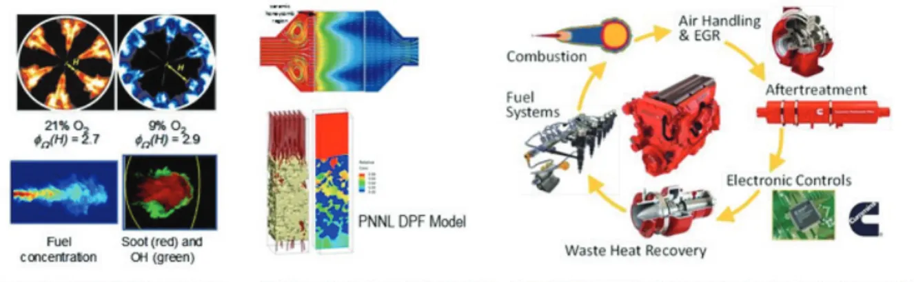
In-cylinder combustion processes will be better understood by exploring use of the fundamental experimental science base leveraging laser-based diagnostics, high-speed sensing and advanced visualization (Figure 8.C.5). Control over combustion chemistry and pollutant species formation depends on the knowledge generated in these experiments.
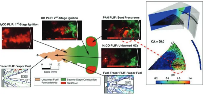
The scope, speed, and resolution of available measurements (Figure 8.C.6) have improved tremendously the physical understanding of the in-cylinder combustion processes needed to minimize the fuel consumption and the carbon footprint of ICEs while maintaining compliance with emissions standards. Improved diagnostic techniques such laser-induced fluorescence measurements15 will permit: quantitative evaluation of air/fuel
mixture distributions formed from injection of fuels; exploration of the applicability of pilot injection strategies for low-temperature combustion (LTC) techniques;16 and provide fundamental understanding (science-base)
needed for industry’s development of practical low-temperature gasoline combustion (LTGC) engines,17
including homogeneous charge compression ignition (HCCI) and partially stratified variants of HCCI. Precision x-ray measurements of the needle lift and motion18 in three dimensions showing significant eccentric motion in
Figure 8.C.5 The science base of in-cylinder spray, combustion, and pollutant-formation processes for both conventional diesel and LTC has radically changed how combustion system designers think about the diesel combustion process and how this process is modeled.
Credit: Sandia National Laboratories
Figure 8.C.6 Laser-induced fluorescence measurements can be used to develop a comprehensive picture of the combustion process that can be compared directly with model results. Notice in particular the good agreement between the measured soot precursors and the simulated fuel-rich zones (dashed red circles).
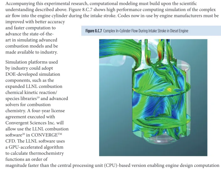
Accompanying this experimental research, computational modeling must build upon the scientific
understanding described above. Figure 8.C.7 shows high performance computing simulation of the complex air flow into the engine cylinder during the intake stroke. Codes now in-use by engine manufacturers must be improved with better accuracy
and faster computation to advance the state-of-the-art in simulating advanced combustion models and be made available to industry. Simulation platforms used by industry could adopt DOE-developed simulation components, such as the expanded LLNL combustion chemical kinetic reaction/ species libraries19 and advanced
solvers for combustion chemistry. A four-year license agreement executed with Convergent Sciences Inc. will allow use the LLNL combustion software20 in CONVERGETM
CFD. The LLNL software uses a GPU-accelerated algorithm to calculate thermochemistry functions an order of
magnitude faster than the central processing unit (CPU)-based version enabling engine design computation on desktop computers.
Research in parallel must increase emission control systems efficiency and durability to comply with emissions regulations at an acceptable cost and with reduced dependence on precious metals. Due to the low exhaust temperature (150°C) of advanced engines, emissions of NOx and PM are a significant challenge for lean-burn
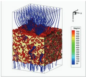
technologies. Numerous technologies must be investigated to reduce vehicle NOx emissions while minimizing the fuel penalty associated with operating these devices. Filtration systems for smaller diameter PM need to be durable and with low fuel economy penalties caused by increased back pressure and filter regeneration. Soot deposition location and resulting soot-loaded wall pressure drops of a catalyzed diesel particulate filter (DPF) can be predicted using advanced computing simulation21 of flow through the wall surfaces (Figure 8.C.8) and
validated with experiments.
R&D will need to examine approaches that are a substantial departure from today’s need to be processes to gain larger reductions in combustion irreversibilities. This will lead to the development with industry of combustion and emission control technologies that offer breakthrough improvements in fuel economy for light- and heavy-duty vehicles. R&D efforts need to focus on operating the engine near peak efficiency over real-world driving cycles to improve the overall vehicle fuel economy. For SI engines, this means reducing the throttling losses with technologies such as lean-burn, high dilution, and variable geometry. Exhaust losses can be reduced with compound compression and expansion cycles made possible by variable valve timing, use of turbine expanders, and waste heat recovery. These approaches could potentially increase light-duty vehicle fuel economy by 35% to 50%, and increase heavy-duty engine efficiency by 30%.
Figure 8.C.8 Catalyzed Particulate Filter Air Flow Modeling at Pacific Northwest National Laboratory
Research and development need to pursue engine hardware changes to implement advanced combustion strategies. These include variable fuel injection geometries, turbo- and super-charging to produce very high manifold pressures, compound compression and expansion cycles, variable compression ratio technologies, and improved sensors and control methods. Advanced sensors and actuators technologies could be rapidly transitioned to the marketplace.
Fuel economy improvements need to be demonstrated by
industry projects that integrate developed high efficiency technologies into vehicles. Integration of a downsized boosted, lean-burn gasoline engine into a production passenger vehicle demonstrated 25 percent fuel economy improvement over the baseline vehicle with port fuel injected (PFI) engine while meeting Tier 2 Bin 2 emission levels.22 Another industry project demonstrated predicted fuel economy increase in a light-duty vehicle on
U.S. cycles with low temperature combustion (LTC) engine can be validated with a vehicle build with realistic packaging.23 Integration of heavy-duty truck engine technologies into a Class 8 long-haul tractor-trailer (e.g.,
SuperTruck) demonstrated the freight fuel economy increase contribution of engine efficiency improvements24 as
well as that of other technologies that improve the overall vehicle system.
Enabling Science Activities
Advancing engine technology to improve vehicle fuel economy will require industry to accelerate its product development cycles, even as it explores innovative designs. The co-optimization of engines and fuels adds additional complexity and opportunities and further highlights the need for efficient product development. Design processes that over-rely on “build and test” prototype engineering are too slow. The challenge of accelerating product design and speeding up market introduction of advanced combustion engines present a unique opportunity to marshal U.S. leadership in science-based simulation to develop new capabilities in predictive computational design to enhance engine performance (Figure 8.C.9). Predictive computational design and simulation tools will shrink engine development timescales, reduce development costs, and accelerate time to market.25
Traditionally, engines are designed to operate on available market fuels, often compromising efficiency and performance. Approached as a system, engines and fuels can be co-optimized using a science-based understanding of how engine efficiency and emissions are impacted by fuel properties, and conversely how engines can be modified to take best advantage of desirable fuel properties.
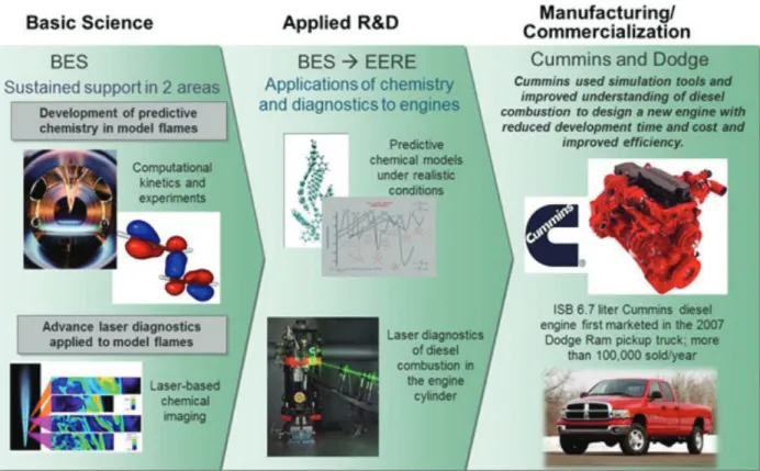
Figure 8.C.9 Basic science research underpins the ongoing development of numerical simulation tools to model, and advanced laser diagnostics to measure, turbulent flames in real, in-cylinder engine combustion. The early success of Cummins in computational simulation used for the ISB engine, although fairly crude by current standards, points the way to more sophisticated, science-based engine design in the future.
and a predictive physics-based fuel property blending model that includes both petroleum-derived fuel and bio-derived fuel blending streams from a variety of sources. Also needed is a comprehensive chemical kinetic mechanisms model that is predictive of the autoignition behavior of the fuels. Simulations of components in a coupled framework of detailed and reduced order computational models will speed up the evaluation of a fuel composition’s impact on the vehicle efficiency and emissions. The combined set of simulation tools will enable a more substantial search for an optimized engine and fuel combination that meets environmental and market goals. Finally, fuels can have important impacts on the overall powertrain system, including after-treatment devices, air-handling devices, and engine thermal management.
Faster dissemination of energy efficient engine technologies into the vehicle population results in earlier
realization of reduction of petroleum consumption and greenhouse gas emissions since combustion engines will remain to be the dominant power source for transportation vehicles in the next several decades.
Key Aspects of DOE Role
Case Studies
Predicting the Influence of injector nozzle needle on fuel
spray development
A robust and predictive nozzle flow, spray and turbulent combustion models for internal combustion engine (ICE) applications have been developed aided by high performance computing (HPC) tools.
The high-fidelity calculations were performed by Argonne National Laboratory (ANL) in collaboration with Convergent Science Inc. At the top is a three-dimensional transient simulation of a multi-hole injector with specified needle off-axis motion (wobble) from start to the end of injection. The mass flow rates through each orifice for a five-hole injector (only three orifices are shown) have been calculated, showing large hole-to-hole differences in the velocity stream lines (and hence mass flow rates) at low needle lift positions. The in-nozzle flow simulations captured the mass flow and cavitation trends very well. The needle wobble is shown to have a profound influence on cavitation characteristics and mass flow rate from
each orifice. These simulations, validated with X-ray experiments at ANL, provide unique insights about the processes governing the fuel injection and liquid spray formation.
The second image shows the influence of needle transients on fuel spray development. Dynamically coupled nozzle flow and spray simulations were performed to capture the near-nozzle dense spray region and were validated against X-ray radiography data from ANL. The simulations predict the spray penetration and dispersion quite well, especially in the near nozzle region and during the initial transients.
The final image captures the plume-to-plume variations in multi-hole nozzles. A reduced chemical kinetic model along with a turbulent combustion model was able to capture the ignition delay and flame lift-off length characteristics quite well.
BES-developed catalyst shows promise for advanced engine
emission control
DOE investigates advanced low temperature combustion (LTC) strategies, such as the reactivity controlled compression ignition (RCCI), because of their high thermal efficiency and significantly lower NOx and PM engine-out emission levels. However, higher hydrocarbon (HC) and carbon
monoxide (CO) emissions require additional controls which are often a challenge with the low exhaust temperature characteristic of these combustion modes.
ORNL tapped on the large Basic Energy Sciences effort that is focused on studying catalysts with very high activity regardless of the specific application for catalyst(s) that have promise for combustion engine exhaust
aftertreatment. ORNL explored the potential of a PGM-free catalyst that demonstrated good stability and very good low temperature CO oxidation at less than 100°C in dry conditions.
One BES-developed catalyst composed of copper oxide, cobalt oxide, and ceria (dubbed CCC) showed such potential.
ORNL investigated the CCC catalyst’s reactivity under simulated exhaust conditions and found that it has two exceptional traits: a) that it maintains high CO reactivity at low-temperatures; and b) that CO oxidation is unaffected by HC oxidation. The
PGM-free CCC catalyst is in fact more reactive than the best Pd-based catalyst that have been studied earlier, Pd/ZrO2-SiO2. PGM catalysts, in contrast, are typically negatively impacted by inhibition from
hydrocarbons and competition for active sites.
ORNL continues in working to identify catalysts that have the potential to be used in low-temperature exhaust environments and to understand how these catalysts function so that more catalysts can be studied that demonstrate similar traits.
100 125 150 175 200 Ex ha us t Tem per at ur e ( C)
1 bar
Conventional Diesel RCCI NOx PM HC COMore Fuel Efficient* Reactivity Controlled Compression Ignition (RCCI) gives higher CO & HCs*
And lower exhaust temperatures*
*vs. Conventional Diesel Combustion RCCI Conv.
Diesel
at 1500rpm, 1 bar
add HC
Inhibition by HCs with PGM
catalysts
No Inhibition
for CCC CCCwithout HC
CCCwith 0.1% HC PGM without HC PGM with 0.1% HC
O2 10%
H2O 5.0%
CO 0.4% NO 0.05% HC (C3H6) 0 or 0.1%
CO Con ve rsi on (%) Temperature (°C)
Public and Private R&D Activities
Knowledge outputs from DOE combustion engine research from 1974 through early 2009 made substantial contributions to downstream innovations in commercial diesel engines and other areas, as documented by the EERE Linkages Study.26
Among the knowledge outputs, 109 DOE-attributed patent families (i.e., groups of patents based on
the same invention) were assigned to multiple organizations, including DOE national laboratories, universities, and companies.
Many combustion patents of the leading innovative vehicle and engine companies linked back to
earlier DOE advanced combustion patent families, e.g., combustion patent portfolios of three leading innovative vehicle and engine companies have built extensively on the DOE-funded advanced combustion research.
DOE R&D has contributed to more-difficult-to-quantify tacit knowledge in the field of advanced
combustion and emission control research, in addition to its explicit knowledge outputs such as patents, publications, models and code, research prototypes, and test data.
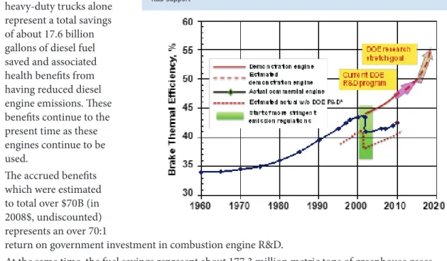
DOE investments in combustion engine R&D from 1986 to 2007 enabled continued efficiency improvements in heavy-duty diesel engine efficiencies while achieving difficult emissions standards. An independent study27
showed that without DOE support, efficiencies would been 4.5 percent lower than what industry was actually able to achieve (Figure 8.C.10).
Accrued benefits
(1995 – 2007) from heavy-duty trucks alone represent a total savings of about 17.6 billion gallons of diesel fuel saved and associated health benefits from having reduced diesel engine emissions. These benefits continue to the present time as these engines continue to be used.
The accrued benefits
which were estimated to total over $70B (in 2008$, undiscounted) represents an over 70:1
return on government investment in combustion engine R&D.
At the same time, the fuel savings represent about 177.3 million metric tons of greenhouse gases
(carbon dioxide equivalent emissions) not being released to the environment.
Although not calculated, this R&D had substantial economic benefits as well, as it enabled heavy-duty engine manufacturers to meet EPA’s strict 2007 regulations which required a 90 percent reduction in particulate matter (PM) emissions and a more than 50 percent reduction in nitrogen oxide (NOx) emissions.
Public/Private Roles going forward
DOE’s R&D roles have been to:
Facilitate development of precompetitive technical knowledge base through investments in
fundamental and applied R&D;
Undertake mid- to long-term pre-competitive research;
Provide access to unique national laboratory expertise and facilities;
Help create a national consensus on R&D areas of common public and private interest; and
Enable public-private partnerships to integrate R&D into industrially useful design tools.
DOE has close communication with industry through a number of working groups and teams, and utilizes these networks for setting goals, adjusting priorities of research, and tracking progress. Examples of the cooperative groups are the Advanced Combustion and Emission Control (ACEC) Tech Team of the U.S. DRIVE Partnership and the Engine Systems Team of the 21st Century Truck Partnership. Focused efforts are carried out in the Advanced Engine Combustion Memorandum of Understanding (Figure 8.C.11), and the CLEERS (Cross-Cut Lean Exhaust Emission Reduction Simulation) activity for the Advanced Engine Cross-Cut Team (Figure 8.C.12) that include auto manufacturers and engine companies, fuel suppliers, national laboratories, and numerous universities. Innovations coming from the R&D of pre-competitive technologies can be transferred to and implemented by industry partners as a business case develops for these technologies.
Figure 8.C.11 close collaboration with industry through the advanced engine combustion MOU led by SNL to develop the knowledge base for advanced combustion strategies and carry research results to products.
Credit: Sandia National Laboratories
Historically, DOE-sponsored heavy-duty engine technologies have been quickly adopted within the commercial heavy truck fleet where fuel economy and fuel costs are major concerns. Engine and emission control
Figure 8.C.12 CLEERS promotes collaboration and interactions among industry, national labs, and universities to achieve functional models for lean emission control devices and systems.
Endnotes
1 Transportation Energy Data Book, Edition 33, ORNL-6990 (Oak Ridge, TN: Oak Ridge National Laboratory, July 2014), http://cta.ornl.gov/
data/tedb33/Edition33_Full_Doc.pdf.
2 Annual Energy Outlook 2014. With Projections to 2040, April 2014. DOE/EIA-0383(2014)
3 Light-Duty Automotive Technology, Carbon Dioxide Emissions, and Fuel Economy Trends: 1975 through 2014. EPA-420-R -14-023.
Washington, D.C. U.S. Environmental Protection Agency, October 2014, p. 53.
4 A Workshop to Identify Research Needs and Impacts in Predictive Simulation for Internal Combustion Engines (PreSICE), March 3, 2011.
Accessed at: http://www1.eere.energy.gov/vehiclesandfuels/pdfs/presice_rpt.pdf
5 Light-Duty Automotive Technology, Carbon Dioxide Emissions, and Fuel Economy Trends: 1975 through 2014. EPA-420-R -14-023.
Washington, D.C. U.S. Environmental Protection Agency, October 2014, p. 53.
6 Report on the Transportation Combustion Engine Efficiency Colloquium held at USCAR, March 3-4, 2010. ORNL/TM-2010/265. Accessed at
http://feerc.ornl.gov/pdfs/Stretch_Report_ORNLTM2010- 265_final.pdf
7 Vehicle Technologies Program Multi-Year Program Plan 2011-2015. Washington, DC., U.S. Department of Energy, December 2010, pp. 2.3-3 –
2.3-4. Accessed at http://www1.eere.energy.gov/vehiclesandfuels/pdfs/program/vt_mypp_2011-2015.pdf
8 Ibid.
9 Report on the Transportation Combustion Engine Efficiency Colloquium Held at USCAR, March 3-4, 2010, ORNL, October 2010.
ORNL/TM-2010/265.
10 Environmental Protection Agency, Tier 3 Vehicle Emission and Fuel Standards Program, http://www3.epa.gov/otaq/tier3.htm. Accessed
October 15, 2015.
• California Air Resources Board, Amendments to the Low-Emission Vehicle Program – LEV III, http://www.arb.ca.gov/msprog/levprog/ leviii/leviii.htm. Accessed October 15, 2015.
11 Vehicle Technologies Program Government Performance and Results Act (GPRA) Report for Fiscal Year 2015, ANL/ESD-14/3 [http://www.
transportation.anl.gov/pdfs/G/955.PDF].
12 Co-optimization of Fuels and Engines – Accelerating the Path to Economic and Sustainable Fuels and Engines, White Paper, Energy Efficiency
13 Overview of the DOE Advanced Combustion Engine R&D Program, June 16, 2014, pp. 41. 14 Ibid.
15 Musculus, M. “Heavy-Duty Low-Temperature and Diesel Combustion & Heavy-Duty Combustion Modeling.” FY 2014 DOE Vehicle
Technologies Program Annual Merit Review; June 16-20, 2014, Washington, D.C.; 25 pp. Accessed March 13, 2015: http://www.energy.gov/ sites/prod/files/ace001_musculus_2014_o.pdf
16 Miles, P. “Light-Duty Diesel Combustion – Experiments and Modeling.” FY 2014 DOE Vehicle Technologies Program Annual Merit
Review; June 16-20, 2014, Washington, D.C.; 32 pp. Accessed March 16, 2015: http://www.energy.gov/sites/prod/files/2014/07/f17/ace002_ miles_2014_o.pdf
17 Dec, J. “Low-Temperature Gasoline Combustion (LTGC) Engine Research.” FY 2014 DOE Vehicle Technologies Program Annual Merit Review;
June 16-20, 2014, Washington, D.C.; 26 pp. Accessed March 16, 2015: http://www.energy.gov/sites/prod/files/2014/07/f17/ace004_dec_2014_o. pdf
18 Powell, C. “Fuel Injection and Spray Research Using X-Ray Diagnostics.” FY 2014 DOE Vehicle Technologies Program Annual Merit
Review; June 16-20, 2014, Washington, D.C.;30 pp. Accessed March 16, 2015: http://www.energy.gov/sites/prod/files/2014/07/f17/ace010_ powell_2014_o.pdf
19 Pitz, W. “Chemical Kinetic Models for Advanced Engine Combustion.” FY 2014 DOE Vehicle Technologies Program Annual Merit Review;
June 16-20, 2014, Washington, D.C.; 28 pp. Accessed March 16, 2015: http://www.energy.gov/sites/prod/files/2014/07/f17/ace013_pitz_2014_o. pdf
20 McNenley, M. “Improved Solvers for Advanced Engine Combustion Simulation.” FY 2014 DOE Vehicle Technologies Program Annual Merit
Review; June 16-20, 2014, Washington, D.C.; 32 pp. Accessed April 7, 2015: http://www.energy.gov/sites/prod/files/2014/07/f17/ace076_ mcnenly_2014_o.pdf
21 Muntean, G. “CLEERS: Aftertreatment Modeling and Analysis.” FY 2014 DOE Vehicle Technologies Program Annual Merit Review; June 16-20,
2014, Washington, D.C.; 30 pp. Accessed March 16, 2015: http://www.energy.gov/sites/prod/files/2014/07/f17/ace023_muntean_2014_o.pdf
22 2013 ACE R&D Annual Report, p. IV-25] 23 Ibid., p. IV-15
24 Koeberlein, D. “Cummins SuperTruck Program.” FY 2014 DOE Vehicle Technologies Program Annual Merit Review; June 16-20, 2014,
Washington, D.C.; 30 pp. Accessed March 16, 2015: http://www.energy.gov/sites/prod/files/2014/07/f17/ace057_koeberlein_2014_o.pdf DTNA SuperTruck. http://www.freightlinersupertruck.com/. Accessed October 16, 2015
25 A Workshop to Identify Research Needs and Impacts in Predictive Simulation for Internal Combustion Engines (PreSICE), March 3, 2011.
Accessed at: http://www1.eere.energy.gov/vehiclesandfuels/pdfs/presice_rpt.pdf
26 Linkages from DOE’s Vehicle Technologies R&D in Advanced Combustion to More Efficient, Cleaner-Burning Engines, June 2011, http://
www1.eere.energy.gov/analysis/pdfs/combustion_linkage082511.pdf. Accessed October 16, 2015.
Acronyms/Glossary
ACEC Advanced combustion and Emission Control
ANL Argonne National Laboratory
BES Basic Energy Sciences
CAFÉ Corporate Average Fuel Economy
CCC Copper oxide, cobalt oxide, and ceria
CFD Computational fluid dynamics
CLEERS Cross-cut Lean Exhaust Emission Reduction Simulation
CO Carbon monoxide
CO2 Carbon dioxide
CO2e Carbon dioxide equivalent
CPU Central processing unit
DOE Department of Energy
DPF Diesel particulate filter
EERE Energy Efficiency and Renewable Energy
EPA Environmental Protection Agency
GHG Greenhouse gas
GPU Graphics processing unit
HC Hydrocarbon
HCCI Homogeneous charge compression ignition
HPC High performance computing
ICE Internal combustion engines
LANL Los Alamos National Laboratory
LLNL Lawrence Livermore National Laboratory
LTC Low temperature combustion
LTGC Low temperature gasoline combustion
Nox Nitrogen oxide
NREL National Renewable Energy Laboratory
ORNL Oak Ridge National Laboratory
PCCI Pre-mixed charge compression ignition
PFI Port fuel injected
PM Particulate matter
RCCI Reactivity controlled compression ignition
R&D Research and development
RD&D Research, Development, and Demonstration