Euclid and His Twentieth
Century Rivals: Diagrams in
the Logic of Euclidean
Geometry
Nathaniel Miller
January 12, 2007
CENTER FOR THE STUDY OF LANGUAGE
only a poet, nor to his problems if he is only an algebraist; but if a man is at once acquainted with the geometric foundation of things and with their festal splendor, his poetry is exact and his arithmetic
musical.”
1 Background 1
1.1 A Short History of Diagrams, Logic, and Geometry 5 1.2 The Philosophy Behind this Work 11
1.3 Euclid’sElements 14
2 Syntax and Semantics of Diagrams 21
2.1 Basic Syntax of Euclidean Diagrams 21
2.2 Advanced Syntax of Diagrams: Corresponding Graph Structures and Diagram Equivalence Classes 27 2.3 Diagram Semantics 31
3 Diagrammatic Proofs 35
3.1 Construction Rules 35 3.2 Inference Rules 40 3.3 Transformation Rules 43
3.4 Dealing with Areas and Lengths of Circular Arcs 45
3.5 CDEG 53
4 Meta-mathematical Results 65
4.1 Lemma Incorporation 65
4.2 Satisfiable and Unsatisfiable Diagrams 72 4.3 Transformations and Weaker Systems 76
5 Conclusions 83
Appendix A: Euclid’s Postulates 89
Appendix B: Hilbert’s Axioms 91
Appendix C: Isabel Luengo’s DS1 95
Appendix D: A CDEG transcript 103
References 115
Background
In 1879, the English mathematician Charles Dodgson, better known to the world under his pen name of Lewis Carroll, published a little book entitledEuclid and His Modern Rivals. Dodgson was concerned by the fact that quite a number of different nineteenth century authors had written their own treatments of planar geometry, most claiming to improve on Euclid, and each one slightly different in the order of its theorems, in which theorems it chose to include, in the proofs given of these theorems, in its treatment of the theory of parallel lines, and in other aspects. Dodgson’s book was written “[i]n furtherance of the great cause which I have at heart—the vindication of Euclid’s master-piece. . . .”1It is written mostly in the form of a dream dialogue between a nineteenth century mathematician, Minos, and the ghost of Euclid. In it, they consider each of the modern rivals in turn, and conclude in each case that, while many of the rivals have interesting things to say, none of them are a more appropriate basis for the study of a beginning geometry student than Euclid’sElements.
At the time at which Dodgson wrote his book, the subjects of ge-ometry and logic were both entering a period of rapid change after having remained relatively constant for two thousand years. There had been enough change already to make Dodgson feel that Euclid needed defending. In the hundred and twenty-five years since then, however, there have been much larger changes in these fields, and, as a result, rather than just undergoing some small changes, Euclidean geometry in general, and Euclid’s proofs in particular, have mostly fallen out of the standard mathematics curriculum. This is at least in part because Euclid’sElements, which was viewed for most of its existence as be-ing the gold standard of careful reasonbe-ing and mathematical rigor, has come to be viewed as being inherently and unsalvageably informal and
1
Dodgson (1885)
FIGURE1 Euclid’s first proposition.
unrigorous.
One key reason for this view is the fact that Euclid’s proofs make strong use of geometric diagrams. For example, consider Euclid’s first proposition, which says that an equilateral triangle can be constructed on any given base. While Euclid wrote his proof in Greek with a single diagram, the proof that he gave is essentially diagrammatic, and is shown in Figure 1.
common is that, because of their use of diagrams, Euclid’s proofs are inherently informal. Under this view, while diagrams may make proofs easier for students and others to follow, proofs that use diagrams can-not be formal because it isn’t clear exactly what rules govern their use. The comments made by Henry Forder inThe Foundations of Euclidean Geometry in 1927 are typical of this view: “Theoretically, figures are unnecessary; actually they are needed as a prop to human infirmity. Their sole function is to help the reader to follow the reasoning; in the reasoning itself they must play no part.”2 Most formal proof systems have therefore been sentential—that is, they are made up of a sequence of sentences in some formal language. It is easy to understand why: it is relatively easy to write down concrete rules that manipulate strings of symbols, in much the same way that algebraic equations are ma-nipulated in high school algebra. Such a sentential axiomatization of geometry was given by David Hilbert in 1899, and since then, his ax-iomatization has replaced Euclid as the commonly accepted foundation of geometry.
However, while Hilbert’s axiomatization has replaced Euclid’s Ele-ments as the theoretical basis for geometry, most informal geometric proofs still use diagrams and more or less follow Euclid’s proof meth-ods. The kinds of diagrams found in Figure 1 should be familiar to anyone who has ever studied planar geometry, and they follow stan-dard conventions: points, lines, and circles in the Euclidean plane are represented by drawings of dots and different kinds of line segments, which do not have to really be straight, and line segments and angles can be marked with different numbers of slash marks to indicate that they are congruent to one another. The formal sentential proofs given in a system like Hilbert’s are very different from these kinds of informal diagrammatic proofs. So, while Hilbert’s system provides a formaliza-tion of the theorems of geometry, it doesn’t provide a formalizaformaliza-tion of the use of diagrams or of many commonly used proof methods. It has been generally assumed that this is because these methods are inher-ently informal; but although theyhavenot been previously formalized, this doesn’t show that theycan not be formalized. A natural question, then, is whether or not diagrammatic proofs like those in Euclid and like the one in Figure 1 can be formalized in a way that preserves their inherently diagrammatic nature.
The central aim of the present book is to show that they can. In fact, the derivation contained in Figure 1 is itself a formal derivation in a for-mal system called FG, which will be defined in the following sections
2
of this book, and which has also been implemented in the computer system CDEG (Computerized Diagrammatic Euclidean Geometry). These systems are based a precisely defined syntax and semantics of Euclidean diagrams. We are going to define a diagram to be a partic-ular type of geometric object satisfying certain conditions; this is the syntax of our system. We will also give a formal definition of which ar-rangements of lines, points, and circles in the plane are represented by a given diagram; this is the semantics. Finally, we will give precise rules for manipulating the diagrams—rules of construction, transformation, and inference.
In order to work with our diagrams, we will have to decide which of their features are meaningful, and which are not. A crucial idea will be that all of the meaningful information given by a diagram is contained in its topology, in the general arrangement of its points and lines in the plane. Another way of saying this is that if one diagram can be transformed into another by stretching, then the two diagrams are essentially the same. This is typical of diagrammatic reasoning, and, although it has not been previously treated formally, this idea has a long informal tradition in geometry. Proclus, the fifth century commentator on Euclid, writes that each case in a geometric proof “announces different ways of construction and alteration of positions due to the transposition of points or lines or planes or solids.” (This is Sir Thomas Heath’s translation, as given in Euclid (1956).) Thus, we see that the idea of considering cases to be different when the arrangements of the geometric objects being considered are topologically different is an ancient one.3
Our formalization of Euclid’s proof methods is useful for several reasons: it lets us better understand his proofs; it allows us to prove metamathematical results about these kinds of proofs; and it shows that there is no inherent reason that the modern foundations of geometry must look completely different from the ancient foundations found in the Elements. Thus the aims of this book are not far removed from Dodgson’s aims in 1879: to show that, while modern developments in logic and geometry may require changes in Euclid’s development, his basic ideas are neither outdated nor obsolete.
3
1.1
A Short History of Diagrams, Logic, and
Geometry
In order to make sense out of this work, we need to put it in historical perspective.
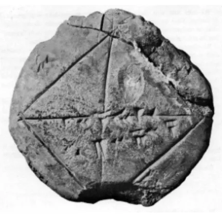
The use of diagrams in geometry has a long history.4 In fact, ge-ometric diagrams are found among some of the oldest preserved ex-amples of written mathematics, such as the Babylonian clay tablets found by archeological digs of ancient Mesopotamian city mounds at the end of the nineteenth century. These tablets, most of which are be-lieved to date from around 1700 B.C., contain some fairly sophisticated arithmetical computations, and a number of them include diagrams. For example, the old-Babylonian tablet shown in Figure 2 (reproduced from Aaboe (1964)) shows the computation of the length of the diago-nal of a square with sides of length 30, using a very good approximation of the square root of two. Geometric diagrams are also found in ancient Egyptian, Chinese, and Indian mathematical works.
It is with the Greeks, though, that mathematics really came into its own, and first and foremost among the Greek mathematical texts that have come down to us is Euclid’sElements. In fact, Euclid’s El-ements was such a seminal work that it has almost entirely eclipsed older Greek mathematical works—even though it wasn’t written until around 300 B.C., long after the crowning achievements of the Greeks in art and literature, and thirty years after Alexander The Great had incorporated Greece into his empire centered in Alexandria, in Egypt. (In fact, Euclid himself lived and worked in Alexandria.) Thus, despite the fact that Euclid’s Elements was part of a rich Greek mathemati-cal tradition dating back to the beginning of the sixth century B.C., almost no earlier Greek mathematical works have come down to us in their entirety. This seems to be largely because The Elements
suc-4
FIGURE2 A Babylonian Tablet dating from around 1700 B.C.
ceeded in incorporating the majority of the preexisting mathematics into its logical development.The Elements has been a preeminent work in mathematics since the time it was written for a number of reasons, and among them is the fact that Euclid set down his assumptions in advance and tried to give explanations for why geometrical facts were true on the basis of his assumptions and previously shown facts. Thus, it is with Greek mathematics that we first encounter the notions of mathematical proof and the logical development of a subject. We also find a precursor of formal symbolic logic in the Greek theory of syllogis-tic reasoning, codified in Aristotle’sPrior Analytics, written about fifty years before Euclid’sElements. Euclid’s main concern inThe Elements was Euclidean geometry, and, as we have already seen, his proofs of geometric facts rely heavily on diagrams. In fact, his first three postu-lates specify diagrammatic actions that can be performed in the course of a proof, although they are often translated in ways that obscure this fact: for example, his first postulate allows you “To draw a straight line from any point to any point.” (See Appendix A for Sir Thomas Heath’s literal translations of Euclid’s Postulates.) Thus, these postu-lates, as originally stated, are hard to understand in any way that isn’t essentially diagrammatic. This will be discussed at greater length later on.
The rise of the Roman Empire around 200 B.C. more or less eclipsed Greek culture, and in particular it eclipsed the Greek mathematical cul-ture with its emphasis on proof. According to a famous story related by Plutarch,5 the Greek mathematician Archimedes was killed during
5
the Roman conquest of the Greek city of Syracuse when he refused to come with an invading soldier until he was done studying a geometric diagram drawn in the sand. The British logician Alfred North White-head, one of the authors of thePrincipia Mathematica, thus remarked on the difference between the Greek and Roman cultures, “No Roman ever lost his life because he was absorbed in contemplation of a math-ematical diagram.”6 As a result, we find fewer new developments in geometry or in logic for quite a long time after 200 B.C. Still, the Ele-mentswere always studied and carefully preserved, first by the Greeks and Romans, and then, after the destruction of Alexandria in 640 A.D., by Arabs in Arabic translations. The most important Arabic contribu-tion to mathematics was probably their development of the subject of algebra. In fact, the wordalgebra comes from the arabic title of a book on the subject written by the Arabic mathematician Muhammad ibn Musa Khwarizmi in the ninth century A.D. In this work, al-Khwarizmi gives numerical methods for solving several different types of equations, followed by geometric proofs that these methods work. Thus, Arabic mathematics combined the subjects of algebra and ge-ometry, using the Greek theory of geometry as the foundation for their developing theory of algebra.
It is not until the European Renaissance that we find steps away from the use of geometry as the foundation of mathematics. The first step came with the invention of analytic geometry in the 1630s by Pierre de Fermat and Ren´e Descartes. These men realized that it was possible to use algebra as a tool for studying geometry, and in doing so, they took the first steps towards a mathematics with arithmetic rather than geometry at its core. In Greek mathematics, geometry was viewed as the foundation for all other branches of mathematics, and so the Greek theories of arithmetic and algebra were based on their theory of geom-etry. The development of analytic geometry allowed mathematicians to instead base the theory of geometry on the theory of numbers, and thus it set mathematics on the path to arithmetization. The develop-ment of integral and differential calculus by Isaac Newton and Gottfried Leibniz independently in the 1660s and 1670s represented another big step in this direction, calculus being a tremendously powerful tool for studying geometric curves by using methods that are essentially arith-metical. The logical conclusion of this path was the definition of the real numbers in terms of the rationals, themselves defined in terms of the natural numbers, by Dedekind, Cantor, and others around 1870. With this development, geometry, with the real numbers at its core,
6
could be seen as a mere extension of arithmetic. Thus, while Plato is quoted by Plutarch as having said that “God ever geometrizes,”7 by the early 1800s this had become Jacobi’s “God ever arithmetizes.”8
Another factor that influenced the shift from geometry to arithmetic as the foundation of mathematics was the discovery of the consistency of non-Euclidean geometries in the 1820s by Gauss, Lobachevsky, and Bolyai. From the time of Euclid, students ofThe Elements had been unsatisfied with Euclid’s fifth postulate. They felt that it was too in-elegant and complex to be a postulate, and that it should therefore be possible to prove from the remaining postulates. Many proofs were proposed and even published, but each turned out to have made some additional assumptions. Finally, two thousand years after Euclid wrote, Gauss, Lobachevsky, and Bolyai each realized that there are consistent geometries in which the first four postulates hold, but the fifth does not. Thus, the fifth postulate cannot not be proven from the first four, because if it could, it would have to be true whenever they were. The discovery of these other geometries greatly weakened Euclidean geom-etry’s claim to be the basis for all other mathematics. Before their dis-covery, it was thought that Euclidean geometry was just a codification of the laws of the natural world, and so it was a natural foundation on which to base the rest of mathematics. After people realized that other geometries were possible and that Euclidean geometry wasn’t necessar-ily the true geometry of the physical world, it no longer had a claim to greater certainty than any other mathematical theory.
The transition from mathematics with geometry at its core to mathe-matics with arithmetic at its core had a profound influence on the way in which people viewed geometric diagrams. When geometric proofs were seen as the foundation of mathematics, the geometric diagrams used in those proofs had an important role to play. Once geometry had come to be seen as an extension of arithmetic, however, geometric di-agrams could be viewed as merely being a way of trying to visualize underlying sets of real numbers. It was in this context that it became possible to view diagrams as being “theoretically unnecessary,” mere “props to human infirmity.”
As the rest of mathematics became arithmetized, so too did logic. The first steps in arithmetizing logic were taken Leibniz in the 1670s and 1680s, when he tried to develop a kind of algebraic system captur-ing Aristotle’s rules for workcaptur-ing with syllogisms. Leibniz’s objective of finding a way of reducing syllogistic logic to algebra was finally realized
7
Plutarch (1878)
8
two hundred years later by George Boole in 1847. Over the next forty years various other people extended Boole’s logical algebra in order to make it applicable to more of mathematics. Notable among them was the American Charles Sanders Peirce, who modified Boole’s algebra to incorporate the use of relations and quantifiers. Finally, in 1879, the same year that Euclid and His Modern Rivals was published, Gottlob Frege published a book containing a logical system roughly equivalent to modern first-order predicate logic.
Interestingly, at the same time that these mathematicians were look-ing at ways to arithmetize logic, others were looklook-ing at ways to dia-gramize logic. The first method for using geometric diagrams of circles to solve syllogistic reasoning problems was given by Euler in 1761. His method of using circles to represent classes of objects was updated and improved by John Venn’s introduction in 1880 of what are now known as Venn diagrams. Another diagrammatic system for representing logi-cal statements was given in C. S. Peirce’s system of Existential Graphs, introduced in 1897. (This is the same C. S. Peirce who had introduced quantifiers into Boole’s algebra.) These Existential Graphs are notable not only for their expressive power, but also for the fact that Peirce gave a collection of explicit rules for manipulating them. Also worth mentioning here is Charles Dodgson, who in 1886 published a book called The Game of Logic, in which he proposed his own system of logic diagrams, equal in expressive power to those of Venn.
In the last decade of the nineteenth century, formal logic was well enough developed that careful axiomatizations of mathematical sub-jects could be given in formal languages. Around 1890, Giuseppe Peano published axiom systems for a number of mathematical subjects in a formal “universal” language that was based on the formalisms devel-oped by Boole and Pierce. Among these were the axiomatization of arithmetic that now bears his name and an axiomatization of Euclidean geometry. Peano’s axiomatization of geometry, along with several oth-ers, was eclipsed by David Hilbert’sFoundations of Geometry, the first version of which was written in 1899.9By this point in time, Euclid’s axiomatization and proofs had come to be seen as being insufficiently rigorous for a number of reasons, among them his use of diagrams. For example, the proof of Euclid’s first proposition, shown in Figure 1 in the previous section, requires finding a point where the two circles in-tersect. Euclid seems to assume that this is always possible on the basis of the diagram, but none of his postulates appear to require the circles
9
to intersect. Hilbert’s axiomatization was meant to make it possible to eliminate all such unstated assumptions. In fact, Hilbert showed that there is a unique geometry that satisfies his axioms, so that any fact that is true in that geometry is a logical consequence of his axioms. However, a proof from Hilbert’s axioms may not look anything like Euclid’s proof of the same fact. For example, Hilbert’s axioms do not mention circles, so any proof of Euclid’s first proposition will have to be very different from Euclid’s proof.
Hilbert’s axiomatization of geometry was part of a larger movement to try to put mathematics on the firmest possible foundation by devel-oping all of mathematics carefully within formal systems that consisted of a small number of given axioms and rules of inference. This movement found its greatest expression in thePrincipia Mathematicaof Bertrand Russell and Alfred North Whitehead, written between 1910 and 1913, which succeeded in developing a huge portion of mathematics from ex-tremely simple axioms about set theory. However, it turned out that the goal of finding a finite set of axioms from which all of mathematics could be derived was impossible to achieve. In 1930, Kurt G¨odel proved his First Incompleteness Theorem, which says approximately that no finite set of axioms is strong enough to prove all of the true facts about the natural numbers. The proof of this theorem involved translating logical statements into numbers and proofs into arithmetical opera-tions on those numbers, and so it can be seen as having completed the arithmetization of logic. In any case, after G¨odel’s theorem was proven, logicians had to content themselves with more modest goals. In gen-eral, they still tried to reason from a small number of carefully specified axioms and rules of inference, because then if the axioms were true in a given domain and the rules of inference were sound, then any theorems proven would be correct.
It was not until recently that modern logic was applied to the study of reasoning that made use of diagrams. In the late 1980s, Jon Bar-wise and John Etchemendy developed a series of computer programs that were meant to help students visualize the concepts of formal logic. These programs,Turing’s World, Tarski’s World, andHyperproof, in-cluded diagrams of a blocks world, and they inspired Barwise and Etchemendy to look more closely at forms of reasoning that used di-agrams. In 1989, they published an article, “Visual Information and Valid Reasoning,” reprinted in Barwise and Allwein (1996), which ad-vanced the hypothesis that diagrammatic reasoning could be made as rigorous as traditional sentential reasoning and challenged logicians to look at diagrammatic reasoning more seriously.
had been done with logic diagrams a hundred years before. As we have seen, the development of systems of logic diagrams roughly mirrored the development of formal algebraic logical systems up to the end of the nineteenth century, but at that point they were for the most part abandoned as the theory of formal systems continued to develop in the twentieth century. Shin finally brought twentieth century developments in logic to bear on the theory of logic diagrams. She put together her own completely formal system of Venn diagrams, based on the earlier work of Euler, Venn, and Peirce, and showed that her system was both sound and complete—that the diagrams that could be derived from a given diagram system were exactly those that were its logical conse-quences. She also extended this system to include a more general form of disjunction and showed that the resulting diagrams had the same expressive power as the monadic first-order predicate calculus.
The first person to try to formalize the uses of diagrams in Euclidean geometry was Isabel Luengo, also a student of Jon Barwise. In her the-sis,10 finished in 1995, she introduced a formal system for manipulat-ing geometric diagrams by means of formal construction and inference rules, and introduced the definition of “geometric consequence,” which extends the notion of logical consequence to domains that include con-struction rules. However, her system does not incorporate the crucial idea that two diagrams should considered equivalent if and only if they are topologically equivalent, and as a result her system is unsound. For a detailed discussion of her formal system and an explanation of why it is unsound, see Appendix C.
In addition to the works just cited, in the time since Barwise and Etchemendy’s article first appeared, many other people working in such varied fields as mathematics, philosophy, computer science, psychology, and cognitive science have taken up their challenge and have examined many different aspects of formal and informal reasoning with diagrams. Books written on aspects of diagrammatic reasoning include Barwise and Allwein (1996), Shin (1994), Hammer (1995), and Greaves (2002). Many interdisciplinary conferences on the subject have also been held, most with published proceedings; see, for example, Anderson et al. (2000), Hegarty et al. (2002), and Blackwell et al. (2004). Diagrammatic reasoning has thus become a growing field of inquiry.
1.2
The Philosophy Behind this Work
It should be stated from the outset that I am a mathematician, not a philosopher. However, the present work rests on and is motivated by
10
several philosophical stances that are worth articulating.
We are going to put together a formal system in which Euclid’s proofs can be formalized. Why should we care if we can do this? As previously discussed, Euclid’sElements was seen as the gold standard in careful deductive reasoning from the time it was written until rela-tively recently, but it is now often viewed as being antiquated, inher-ently informal, and unsalvageable. So we might wonder which view is correct: are Euclid’s methods of proof valid, or are they not? First off, let us note that it isn’t quite clear what the question even means. In a formal system, we have a clearly defined notion of whether or not a proposed inference rule is valid—it is valid if it always gives a true conclusion when provided with true hypotheses. Euclid’s proofs, how-ever, are not part of a formal system in the modern sense, so we can’t apply this test to them. This, by itself, doesn’t mean that his methods are incorrect—only that they are informal. There are certainly informal proofs that mathematicians accept as being correct; in fact, practicing mathematicians almost never give proofs of their results in a formal system. Rather, they accept the idea that formal systems for doing mathematics exist, and if pressed might claim that their proofs could be translated into such a formal system. (This was the expressed pur-pose of thePrincipia Mathematica mentioned in the previous section.) So one possible meaning for the question, “Did Euclid use valid infor-mal methods of proof?” is “Is it possible to create a forinfor-mal system such that Euclid’s informal proofs can be translated into formal proofs in this system?”
In some sense we are giving a kind of definition of what it means to have a valid informal method of giving proofs. We will call this the
formality hypothesis:
Hypothesis 1 (Formality Hypothesis) An informal proof method is sound if and only if it is possible to give a formal system with the property that informal proofs using the informal methods can always be translated into equivalent correct proofs in the formal system.
Several important points about this hypothesis should be made:
.
It gives us a basis for evaluating informal methods of proof..
It is inherently subjective and non-mathematical, because theques-tion of what constitutes an “equivalent” formal proof is necessarily subjective.
.
For this reason, it isn’t possible to prove or disprove this hypothesis,and thus it is more like a definition than like a conjecture.
.
It differs from a more traditional formalist position in that the basicwe aren’t just saying that a statement is true if a formal version of that statement can be proven in a formal system. We are saying that a proof of the statement is correct if the formal version of the statement can be proven by a formal version ofthat proof in a formal system.
In general, this hypothesis allows us to analyze the properties of an informal proof system by looking at the properties of a corresponding formal system.
Thus, the goal of this book is to give such a formal system in which Euclid’s proofs can be duplicated. We will take the view that Euclid’s proof methods should be viewed as being correct as long as they can be duplicated in our proof system. And we will prove meta-mathematical results about our formal system to try to shed some light on the prop-erties of informal Euclidean geometric proofs. On the other hand, the existence of this formal system, showing that Euclid’s proof methods can be formalized, provides support for the formality hypothesis.
One additional point that needs to be clarified here is the question of what we are willing to consider to be a formal system for the purposes of evaluating our hypothesis. The simplest possible definition that we can adopt here is that a system is completely formal if it can be completely implemented on a computer. This may seem obvious, but it means that the objects manipulated by the formal system can be anything at all as long as they can be translated into finite objects that a computer can manipulate. In the case of Euclidean geometry, this means that our formal system can manipulate diagrams, as long as we have some way representing the diagrams as finite objects in a computer.
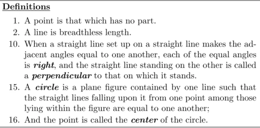
TABLE1 Some of Euclid’s definitions from Book I ofThe Elements.
Definitions
1. A point is that which has no part. 2. A line is breadthless length.
10. When a straight line set up on a straight line makes the ad-jacent angles equal to one another, each of the equal angles isright, and the straight line standing on the other is called aperpendicularto that on which it stands.
15. A circle is a plane figure contained by one line such that the straight lines falling upon it from one point among those lying within the figure are equal to one another;
16. And the point is called the centerof the circle.
1.3
Euclid’s
Elements
We are going to put together a formal system to formalize the kinds of proofs found in Euclid’sElements. Until the last century or so, any well-educated person would have studied Euclid’sElements, but since that is no longer the case, this section provides an introduction to that work. All of the quotations from the Elements given here are taken from Sir Thomas Heath’s translation.11
Euclid’sElements consists of twelve books. The first four books are about elementary planar geometry; this is the part of the Elements that we would like to be able to formalize. Books five through ten are largely about the theory of ratio and proportion and about what would now be considered number theory; and books eleven through thirteen are about three dimensional geometry, and work their way up to the constructions of the five platonic solids. We will only be interested here in the kinds of proofs found in the first four books, which are the same kinds of proofs that are usually given in informal treatments of planar geometry today.
Euclid starts by giving twenty-three definitions, along with five pos-tulates and five common notions. These pospos-tulates and common no-tions, along with several of the definino-tions, are given in Tables 1, 2, and 3. They are also reproduced, for the reader’s convenience, in Ap-pendix A.
The definitions that Euclid gives are really of two types. Some of his definitions, such as that of a circle in Definition 15, give specific
defin-11
TABLE2 Euclid’s Postulates fromThe Elements.
Postulates
Let the following be postulated:
1. To draw a straight line from any point to any point.
2. To produce a finite straight line continuously in a straight line.
3. To describe a circle with any center and distance. 4. That all right angles are equal to one another.
5. That, if a straight line falling on two straight lines make the interior angles on the same side less than two right angles, the two straight lines, if produced indefinitely, meet on that side on which are the angles less than the two right angles.
TABLE3 Euclid’s Common Notions fromThe Elements.
Common Notions
1. Things which are equal to the same thing are also equal to one another.
2. If equals be added to equals, the wholes are equal.
3. If equals be subtracted from equals, the remainders are equal. 4. Things which coincide with one another are equal to one
an-other.
ing properties that the object defined must have. These definitions are concrete and are sometimes used in his proofs. Other definitions, like that of a point given in Definition 1, give more general descriptions of the objects being described. They describe an object, but not in terms of properties that could be concretely used in a proof. A reader who already knows what a point is will probably agree that it “has no part,” but a reader who didn’t probably wouldn’t find find this defi-nition very useful. For this reason, modern treatments generally prefer to leave terms like this undefined. In such a treatment, we consider that the axioms could be referring to any model in which they are true, even if the points, lines,etc.might look very different in such a model than in what we consider to be the standard Euclidean plane. The fact that Euclid does give definitions of these terms shows that this isn’t his intent: he has a particular model in mind, and gives an informal description of each kind of basic object in this standard model.
Euclid’s Postulates and Common Notions set down the assumptions that he will use in his proofs. The Common Notions set down assump-tions that are supposed to be true in general, while the Postulates set down the assumptions that are supposed to be particular to geometry. Thus, for example, Common Notion 1 states the transitive law of equal-ity, which is still commonly taken as an axiom in formal treatments of many different fields of mathematics.
I, 1: “For every two points A, B there exists a line a that contains each of the points A, B.” The difference is subtle but important. The statement of an allowed rule in our proof system has been changed into a statement of fact in the underlying model.
Postulates two and three are also construction postulates. Postu-late two means that any finite straight line segment can be extended indefinitely in either direction, making an infinite straight line. Postu-late three says a circle can be drawn about any center point through any other point. Again, these specify allowed diagrammatic operations, which correspond to the operations that can be carried out with a straight edge and compass.
Postulate four seems trivial on a first reading, but really is not. Euclid’s definition of a “right angle” is not one that is ninety degrees, but rather one that divides a straight line into two equal pieces. Thus, the postulate says that all such right angles, and therefore all straight lines, are the same everywhere. In effect, it says that the surface is uniform; it fails on surfaces like cones where some points are different than others.
The fifth postulate is the one that has been viewed by many readers through the ages as being too complicated to be taken as an axiom. The existence of non-Euclidean geometries in which it isn’t true shows that it cannot be derived from the other postulates, however. We won’t have a lot more to say about the fifth postulate here, except to note that, unlike most of the other proposed alternatives, Euclid’s fifth postulate says nothing directly about parallel lines.
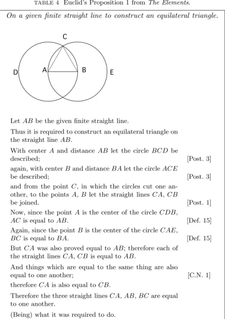
TABLE4 Euclid’s Proposition 1 fromThe Elements.
On a given finite straight line to construct an equilateral triangle.
E D
C
B A
LetABbe the given finite straight line.
Thus it is required to construct an equilateral triangle on the straight lineAB.
With center A and distanceAB let the circle BCD be
described; [Post. 3]
again, with centerBand distanceBAlet the circleACE
be described; [Post. 3]
and from the point C, in which the circles cut one an-other, to the pointsA,B let the straight linesCA,CB
be joined. [Post. 1]
Now, since the pointAis the center of the circleCDB,
AC is equal toAB. [Def. 15]
Again, since the pointBis the center of the circleCAE,
BCis equal toBA. [Def. 15]
ButCAwas also proved equal toAB; therefore each of the straight linesCA,CB is equal toAB.
And things which are equal to the same thing are also
equal to one another; [C.N. 1]
thereforeCAis also equal toCB.
Therefore the three straight linesCA,AB,BCare equal to one another.
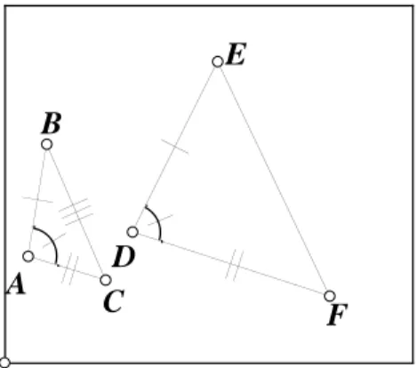
TABLE5 Euclid’s Proposition 4 fromThe Elements.
If two triangles have the two sides equal to two sides respectively, and have the angles contained by the equal straight lines equal, they will also have the base equal to the base, the triangle will be equal to the triangle, and the remaining angles will be equal to the remain-ing angles respectively, namely those which the equal sides subtend.
F E
D C B
A
Let ABC,DEF be two triangles having the two sides AB, AC equal to the two sides DE, DF respectively, namelyAB toDEandAC to DF, and the angleBAC equal to the angleEDF.
I say that the baseBCis also equal to the baseEF, the triangleABCwill be equal to the triangleDEF, and the angleACBto the angleDF E.
For, if the triangleABCbe applied to the triangleDEF, and if the point A be placed on the point D and the straight lineABonDE, then the pointBwill also coin-cide withE, becauseABis equal toDE.
Again,ABcoinciding withDE, the straight lineACwill also coincide withDF, because the angleBAC is equal to the angleEDF;
hence the point C will also coincide with the point F, becauseAC is again equal toDF.
But B also coincided with D; hence the base BC will coincide with the baseEF.
[ For if, whenBcoincides withEandCwithF, the base BC does not coincide with the base EF, two straight lines will enclose a space: which is impossible.
Therefore the baseBC will coincide with EF ] and will
be equal to it. [C.N. 4]
Thus the whole triangle ABC will coincide with the whole triangleDEF, and will be equal to it.
And the remaining angles will also coincide with the re-maining angles and will be equal to them, the angleABC to the angleDEF, and the angleACBto the angleDF E.
Thereforeetc.
diagrams is a formalization of the particular proof that Euclid gives, because the steps in the diagrammatic proof directly correspond to the steps that Euclid describes in his written proof.
One other proof that is worth looking at here is Euclid’s proof of his Proposition 4, which is given in Table 5. This is his proof of the triangle congruence theorem usually referred to as Side-Angle-Side, or SAS for short. It says that if two triangles have an angle that is the same size in both, and such that the lengths of the sides that extend from this angle are the same size in both triangles, then the triangles must be congruent, meaning that one can be placed on the other so that they coincide, and that all of the other parts of the triangles must therefore be equal in size as well.
Note that part of the proof is enclosed in brackets; it is Heath’s opinion that this piece is probably a later addition to the proof, and not in Euclid’s original version.
Euclid proves this proposition by the method of superposition: he shows that if one triangle is placed on the other, then they will exactly coincide. Commentators on Euclid’sElements have widely objected to this method, as is discussed by Heath, for both philosophical and math-ematical reasons. The mathmath-ematical reasons again mostly boil down to the idea that lots of assumptions have crept in here, and it is not clear precisely what the rules of using this method are. Euclid’s stated assumptions say nothing about moving figures, although his common notion 4 is clearly included for the purpose of being cited here. Hilbert includes Side-Angle-Side as an axiom, rather than proving it. Many commentators also note that Euclid only rarely uses this method of proof, and, after having used it to prove Side-Angle-Side, tends to use Side-Angle-Side instead of using the method of superposition, and con-clude that Euclid himself viewed the method as being suspect. Heath, for example, writes that “Euclid obviously used the method of super-position with reluctance. . . .”
Syntax and Semantics of Diagrams
As we have seen in the previous chapter, Euclid’s proofs are inherently diagrammatic. Therefore, our first step in putting together a formal system to mimic Euclid’s proofs will have to be to define precisely what we mean by a diagram in this context. Furthermore, as noted in Section 1.2, in order for our system to be completely formal and computerizable, we will need to give a definition with the property that all of the information contained in a diagram can also be encapsulated in a finite way in a computer.
2.1
Basic Syntax of Euclidean Diagrams
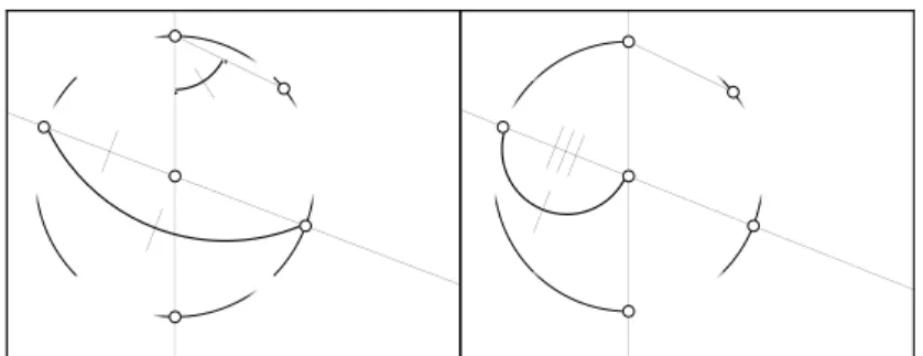
Figure 3 shows two examples of the sort of diagrams we want to con-sider. They contain dots and edges representing points, straight lines and circles in the plane, but note that a diagram may not look exactly like the configuration of lines and circles that it represents; in fact, it may represent an impossible configuration, like the second diagram in Figure 3.
Formally, we define a diagram as follows:
FIGURE3 Two primitive diagrams.
Definition 1 Aprimitive Euclidean diagramDis a geometric ob-ject in the plane that consists of
1. a rectangular box drawn in the plane, called aframe;
2. a finite set DOTS(D) of dotswhich lie inside the area enclosed by the frame, but cannot lie directly on the frame;
3. two finite sets SOLID(D) and DOTTED(D) ofsolid and dotted line segments which connect the dots to one another and/or the frame, and such that each line segment
(a) lies entirely inside the frame,
(b) is made up of a finite number of connected pieces that are either straight lines or else arcs of circles, which intersect each other only at their endpoints, and such that each of these pieces intersects at most one other piece at each of its endpoints,
(c) does not intersect any other segment, any dot, the frame, or itself except at its endpoints, and
(d) either forms a single closed loop, or else has two endpoints, each of which lies either on the frame or else on one of the dots;
4. a set SL(D) of subsets of SOLID(D), such that each segment in SOLID(D) lies in exactly one of the subsets; and
l1 l1
l2 l3
l3 l2
l1 l1
l2
l2
l3
l3
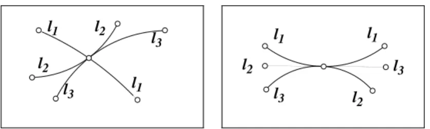
FIGURE4 Examples of diagrammatic tangency.
exactly one dcircle. A dline or dcircle is said to intersect a given dot (or the frame)ntimes if it has ncomponent segments with endpoints on that dot (or on the frame), counting a segment twice if both of its endpoints lie on the frame or on the same dot. Notice that it follows from the preceding definition that dlines and dcircles can only inter-sect other dlines and dcircles at dots (or on the frame, but this will eventually be disallowed).
We are now going to put some constraints on these diagrams to try to make sure that they look as much as possible like real configurations of points, lines, and circles in the plane. To begin, we would like to ensure that the dlines and dcircles come together at a dot in a way that mimics the way that real lines and circles could meet at a point. To this end, we first define the notion of diagrammatic tangency:
l
1l
2FIGURE5 A non-viable primitive diagram
once by specifying that if eis such a dline, andeintersects ddirectly between two members of the same dtangency equivalence class, then eis dtangent to all of the members of that equivalence class. Thus,l1 andl2in Figure 5 are dtangent to one another under this definition. A dline that only intersectsdonce is said toend atd.
We can now define a dotdto be viable as follows:
Definition 3 A dot isviableif
1. any dcircle that intersects the dot intersects it exactly twice; 2. any dline that intersects the dot intersects it at most twice; 3. the dcircles and dlines that intersectddo so in such a way so as
to make the dtangency relation transitive; and 4. no two dlines are dtangent atd.
A primitive diagramD is viable if every dot inD is viable.
l
l
c
FIGURE6 A viable diagram that isn’t well-formed.
Next, we would like to ensure that the dlines and dcircles of our diagrams behave like real lines and circles. We do this with the following definition.
Definition 4 A primitive diagram D is well-formed if it is viable and
1. no dotted line segment inD intersects the frame;
2. no two line segments intersect the frame at the same point; 3. every dline and dcircle inD is connected—that is, given any two
dots that a dline or dcircleP intersects, there is a path from one to the other along segments inP;
4. every dline has exactly two ends, where theends of a dline are defined to be the points where it intersects the frame or a dot which it only intersects once; and
5. every dcircle inDis made up of segments that form a single closed loop such that the center of the dcircle lies inside that loop.
We call a dline that intersects the frame twice a proper dline; one that intersects the frame once ad-ray; and one that doesn’t intersect the frame at all adseg(not to be confused with the solid line segments that make it up). A well-formed primitive diagram is also called awfpd. Figure 6 shows a viable diagram that isn’t well-formed and violates each of the four clauses of the definition. Both of the diagrams in Figure 3, however, are well-formed.
there is only one way to assign segments to dlines and dcircles that is consistent with the diagram being well-formed, because you can de-termine which segments belong to the same dline or dcircle at a given dot by looking at the clockwise order in which the segments intersect the dot. In practice, it is usually clear which segments are intended to belong to the same dline or dcircle, and we won’t indicate this unless it is unclear. We could also prove a theorem showing that every viable primitive diagram is equivalent to one in which two segments that in-tersect at a given dot are on the same dline iff they locally lie on a straight line, and are on the same dcircle iff they locally lie on some circle.
Finally, we have the following:
Definition 5 A primitive diagram isnicely well-formed if it is well-formed and
1. no two dlines intersect more than once;
2. no two dcircles intersect more than twice;
3. no dline intersects any dcircle more than twice;
4. if a dline is diagrammatically tangent to a dcircle, then they only intersect once;
5. if a dline intersects a dcircle twice, then the part of the dline that is between the two intersection points must lie on the inside of the dcircle; and
6. given any two non-intersecting proper dlines, if there is a third dline that intersects one of them, then it also intersects the other.
The last clause of this definition makes non-intersection of dlines an equivalence relation, and corresponds to the uniqueness of parallel lines. The first diagram in Figure 3 is nicely well-formed under two of the three assignments of segments to dlines and dcircles that make it a wfpd. The second diagram in Figure 3 is not nicely well-formed, since it contains two dlines that intersect twice. Nicely well-formed primitive diagrams are also callednwfpds.
2.2
Advanced Syntax of Diagrams: Corresponding
Graph Structures and Diagram Equivalence
Classes
We have now defined a primitive diagram to be a particular kind of geometric object. These diagrams contain somewhat too much infor-mation, though. We want the objects manipulated by our formal sys-tem to only contain a finite amount of information. As it stands, if we have a diagram containing only a single dot, that dot could be at any one of an infinite number of points inside the frame. We could spec-ify its position by a pair of real numbers, but real numbers can have infinite decimal expansions, and therefore take an infinite amount of information to specify. We don’t actually care exactly where the point is, however. We’re not going to use the information about the specific location of the point. Instead, we’re only going to use our diagrams to show the topology of how lines and circles might lie in the plane. For example, all of the diagrams that only contain a single dot have the same topology, even though each one is slightly different, so we’d like to consider them to all be the same diagram in some sense. In other words, we’d really like to look at equivalence classes of diagrams that contain the same topological information. In order to do this, we are going to define for each diagram an algebraic structure called acorresponding graph structure(abbreviatedcgs). The definition will be somewhat technical, but the idea is simple: the diagram’s corresponding graph structure just abstracts the topological information contained in the diagram. Another way of saying this is that our definition will have the property that two diagrams will have isomorphic corresponding graph structures just if they have the same topological structure. As noted in Chapter 1, while this formal treatment is new, informal versions of this idea are ancient.
Some readers who are not interested in the technical details of this definition may wish to skip ahead to Definition 8, especially on a first reading.
the graph it lies in.
(Two vertices v1 and v2 in a graph Gare said to be connected if there is a path from v1 to v2 in G, and they are said to be doubly
connected if for any edgeeof G, there is a path fromv1 tov2 in the graph obtained from Gby removing edge e. Being connected or dou-bly connected are equivalence relations, and their equivalence classes are called the connected or doubly connected components of G. The notion of a cell complex is a standard idea from algebraic topology; for reference, see any standard text book such as Hatcher (2002), which is freely available online.)
The notion of a cgs will be useful because we really want to think of two diagrams as being the same if they contain the same topolog-ical information, and so we will form equivalence classes of diagrams that have the same (isomorphic) corresponding graph structures. The corresponding graph structures are nice, constructive, algebraic objects that we can manipulate, reason formally about, or enter into a com-puter, rather than working directly with the equivalence classes. The data structures thatCDEGuses to represent diagrams are essentially a version of these corresponding graph structures.
We start by defining the appropriate type of algebraic structure to capture the topology of a diagram.
Definition 6 Adiagram graph structureS consists of 1. a set of verticesV(S);
2. a set of edgesE(S);
3. for each vertexvinV(S), a (cyclical) listL(v) of edges fromE(S) (which lists in clockwise order the edges that are connected tov, telling us how to make the edges and vertices into a graph); 4. a two-dimensional cell-complex for each doubly connected
com-ponent of the graph;
5. a functionerS from the non-outermost connected components of
the graph to the two-cells of the cell-complexes (er stands for “enclosing region”, and this function tells us which region each connected component lies in);
6. a subset DOTS(S) ofV(S);
7. two subsets ofE(S), called SOLID(S) and DOTTED(S); 8. a set SL(S) of subsets ofE(S); and
9. a set CIRC(S) of pairs whose first element is a vertex and whose second element is a set of edges.
the frame in a finite number of points, which divide the frame into a finite number of pieces. We refer to these points aspseudo-dotsand to these pieces aspseudo-segments.
Definition 7 A diagram D’s corresponding graph structure is a diagram graph structureS with the following properties:
1. V(S) contains one vertexG(d) for each dot or pseudo-dotdinD. 2. E(S) contains one edge for every segment and pseudo-segment in
D.
3. Ifd is any dot or pseudo-dot inD, thenL(G(d)) lists the edges corresponding to the segments and pseudo-segments that inter-sectd, in the clockwise order in which the segments and pseudo-segments intersectd.
4. For each doubly connected componentP of the graphGdefined byV(S),E(S), and the lists L(v), we define its corresponding cell complexCP as follows:
(a) CP contains two-dimensional cells, one-dimensional cells,
and zero-dimensional cells.
(b) For each vertex v in P, CP contains a corresponding 0-cell
C(v).
(c) For each edge e of P, CP contains a corresponding 1-cell
C(e).
(d) Note that the segments and pseudo-segments ofD that cor-respond to edges inP break up the plane into a finite num-ber of connected regions, since there are only finitely many of them and they are piecewise arcs of circles and lines. Fur-thermore, becausePis doubly connected, all but one of these (which we’ll call the outer region) are simply connected. For each such simply connected regionr, CP contains a
corre-sponding two-cellC(r).
(e) CP is put together by connecting the zero-cells to the
one-cells so that the boundary of C(e) is the set contain-ing C(v1) and C(v2) iff e connects v1 and v2 in G; and then attaching the two-cells to the resulting cell-complex so that the boundary of C(r) is the loop that traverses (C(G(s1)), C(G(s2)), . . . , C(G(sn))) in order if and only if
the boundary ofr in D consists precisely of (s1, s2, . . . , sn)
in clockwise order.
5. For each connected componentpofGthat does not contain the edges corresponding to the pieces of the frame, erS(p) is the
(a) the parts ofD that correspond toplie entirely inr, and (b) if they also lie entirely in a regionr′ corresponding to some
other two-cellS, thenris contained inr′.
6. Each of the sets DOTTED(S), SOLID(S), DOTS(S), SL(S), and CIRC(S) is defined so that an element aof S is in one of these sets iff the corresponding element ofDis in the corresponding set inD.
This definition now allows us to say what it means for two diagrams to contain the same information.
Definition 8 Two diagrams D and E are equivalent (in symbols, D≡E) if they have isomorphic corresponding graph structures. This is an equivalence relation, and we normally won’t distinguish be-tween equivalent diagrams. If two diagramsD and E are equivalent, then there is a natural mapf between the dots and segments of one diagram and the dots and segments of the other; we say that D and Eare equivalentvia f. If two graphs have corresponding graph struc-tures that are isomorphic except that the orientations are all reversed, then we say that the diagrams arereverse equivalent.
Next, we would like extend our notion of a geometric diagram to allow us to mark diagrammatic angles and segments as being congruent to other diagrammatic angles and segments. Adiagrammatic angle
ordi-angleis defined to be an angle formed where two dlines intersect at a dot in a diagram. (They do not have to be adjacent to one another.) Amarked diagramis a primitive diagram in which some of the dsegs and/or some of the di-angles have beenmarked. A dseg is marked by drawing a heavy arc from one of its ends to the other and drawing some number of slash marks through it. If the dseg is made up of a single solid line segment, then it can also be marked by drawing some number of slash marks directly through the line segment. A di-angle is marked by drawing an arc across the di-angle from one dline to the other and drawing some number of slash marks through it. The arc and slash marks are called a marker; two dsegs or di-angles marked with the same number of slashes are said to be marked with the same marker. A single dseg or di-angle can be marked more than once by drawing multiple arcs.
FIGURE7 A diagram array containing two marked versions of the first primitive diagram in Figure 3.
first diagram in Figure 3.
We can extend our notion of diagram equivalence to marked di-agrams and diagram arrays in the natural way. We define amarked diagram graph structureto be a diagram graph structure along with a new set MARKED whose elements are sets of dsegs and sets of or-dered triples of the form<vertex,edge,edge>. We next define a marked primitive diagram D’s corresponding marked graph structure to con-sist of the corresponding graph structure ofD’s underlying unmarked primitive diagram along with a set MARKED that for each segment marker in D contains the set of dsegs corresponding to the segments marked by that marker, and for each di-angle marker in D contains the set of triples <v, e1, e2> such that the di-angle with vertex corre-sponding tov and edges corresponding toe1 ande2in clockwise order is marked with that marker. Two marked diagrams are defined to be equivalent if and only if their corresponding marked graph structures are isomorphic; and two diagram arrays are equivalent if and only if there is a bijection f from the diagrams of one to the diagrams of the other that takes diagrams to equivalent diagrams.
2.3
Diagram Semantics
edges.
It is very easy to turn a Euclidean planeP into a diagram. We can do this as follows: pick any new pointnin P, pick a pointpl on each
designated linel of P, and let mbe the maximum distance fromnto any designated point, any pl, or to any point on a designated circle.
mmust be finite, sinceP only contains a finite number of designated points, lines and circles. LetR be a circle with centernand radius of length greater thanm, and letFbe a rectangle lying outside ofR. Then if we letDbe a diagram whose frame isF, whose segments are the parts of the edges ofP that lie insideF, whose dots are the designated points ofP, and whose dlines and dcircles are the connected components of the lines and circles ofP, thenDis a nwfpd that we callP’scanonical (unmarked) diagram. (Strictly speaking, we should say a canonical diagram, since the diagram we get depends on how we pick n and the pl; but all the diagrams we can get are equivalent, so it doesn’t
really matter.) We can also find P’s canonical marked diagram
by marking equal those dsegs or di-angles in D that correspond to congruent segments or angles in P. These canonical diagrams give us a convenient way of saying which Euclidean planes are represented by a given diagram.
Definition 9 A Euclidean plane M is a model of the primitive dia-gramD (in symbols,M |=D, also read as“M satisfiesD”) if
1. M’s canonical unmarked diagram is equivalent toD’s underlying unmarked diagram, and
2. if two segments or di-angles are marked equal inD, then the corre-sponding segments or di-angles are marked equal inM’s canonical marked diagram.
M is a model of a diagram array if it is a model of any of its component diagrams.
This definition just says that M |= D if M and D have the same topology and any segments or angles that are marked congruent in D really are congruent in M. Note that this definition makes a diagram array into a kind of disjunction of its primitive diagrams and that the empty diagram array therefore has no models.
E may have different markings. However, it is true if D and E are unmarked. Also, if D is a primitive diagram that isn’t nicely well-formed, then it has no models. To see this, notice that ifM |=D, then D’s underlying unmarked diagram D′ is equivalent to M’s canonical unmarked diagram, which is nicely-well formed; soD′is also nicely well-formed, as diagram equivalence preserves nice well-formedness, and so Dis nicely well-formed since its underlying unmarked diagram is nicely well-formed.
We are going to use diagrams to reason about their models. In order to do this, we are going to define rules that will allow us to perform operations on given diagrams which return other diagrams. So we will need some way of identifying diagrammatic elements across diagrams. To do this, we can use a counterpart relation, denoted cp(x, y), to tell us when two diagrammatic objects that occur in different primi-tive diagrams are supposed to represent the same thing. Formally, the counterpart relation is a binary relation that can hold between two dots or two sets of segments in any of the primitive diagrams that oc-cur in some discussion or proof, but never holds between two dots or sets of segments that are in the same primitive diagram. Informally, people normally use labels to identify counterparts. For example, two dots in two different diagrams might both be labeled A to show that they represent the same point. The idea of a counterpart relation is due to Shin.12
12
Diagrammatic Proofs
Now that we have a careful definition of what constitutes a diagram, we are ready to start putting together our formal system that will manipulate these diagrams.
3.1
Construction Rules
First of all, we need a way to use diagrams to model ruler and compass constructions like those found in theElements. In order to do this, we will define several diagram construction rules. The rules work as fol-lows: the result of applying a given rule to a given nwfpdDis a diagram array of (representatives of all the equivalence classes of) all the nwfpds that satisfy the rule (with corresponding parts of the diagrams identi-fied by the counterpart relation). In effect, we are making sure that all of the different topological cases that could result when we apply the construction rule are considered. The new dlines and dcircles added by these rules are allowed to intersect any of the already existing dlines and dcircles, and the intersection points can be at new dots, as long as the resulting diagrams are still nicely well-formed. There will always be a finite number of resulting nwfpds, since each application of a rule will add a single new dot, dline, or dcircle, and the original diagram can only contain a finite number of dots and segments, none of which can be intersected more than twice by the new element, because of the conditions for niceness. We can apply the construction rules to dia-gram arrays by applying the rules to the individual primitive diadia-grams contained in the arrays. The diagram construction rules are given in Table 6.
Rule C3a is a special case of rule C3b, while C3b is derivable from C3a, as shown in Euclid’s second proposition. Rules C1, C2, and C3a correspond to Euclid’s first three postulates. Euclid’s Postulates can be found in Appendix A.
TABLE6 Diagram Construction Rules.
Diagram Construction Rules
C0. A dot may be added to the interior of any region, or along any existing segment, dividing it into two segments (unless the original segment is a closed loop, in which case it divides it into one segment).
C1. If there isn’t already one existing, a dseg may be added whose endpoints are any two given existing distinct dots.
C2. Any dseg (or dray) can be extended to a proper dline. C3a. Given two distinct dotsc andd, a dcircle can be added with
centerc that intersectsdif there isn’t already one existing. C3b. Given a dot c and a dseg S, a circle can be drawn about
centerc, withS designated to be adradiusof the dcircle. In general, we define a dseg to be a dradius of a dcircle if it is so designated by an application of this rule or if one of its ends lies on the dcircle and the other lies on the dcircle’s center. C4. Any dline or dcircle can be erased; any solid segment of a
dline may be erased; and any dot that doesn’t intersect more than one dline or dcircle and doesn’t occur at the end of a dseg or dray can be erased. If a solid line segment is erased, any marking that marks a dseg or di-angle that it is a part of must also be erased.
C5. Any new diagram can be added to a given diagram array.
D
C
B
A
A
B
B
A
C
D
D
C
C
D
A
B
C
D
A
B
D
C
A
B
D
C
A
B
D
B
A
C
D
A
B
C
D
C
B
A
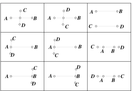
FIGURE9 The result of applying rule C1 to pointsC andD in the diagram in Figure 8.
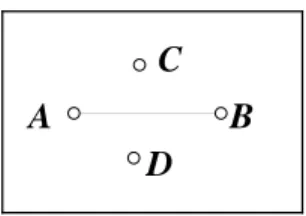
As a relatively simple example of how these rules work, consider the diagram shown in Figure 8. What happens if we apply rule C1 to this diagram in order to connect points Cand D? We get the diagram ar-ray of all nwfpds extending the given diagram in which there is a dseg connecting pointsC andD. In this case, there are nine different topo-logically distinct possibilities, asCDEGconfirms, which are shown in Figure 9. See Section 3.5 for a discussion of CDEG that includes a discussion of CDEG’s output in this case, with a detailed discussion of how it arrives at these nine possibilities.
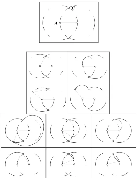
less carefully, there would have been others. Let’s consider what would have happened if we had eliminated the fourth and fifth clauses in the definition of nice well-formedness (Definition 5), which say that if a dline intersects a dcircle twice, then the part of the dline that lies between the two intersection points must also lie inside the dcircle, and the dcircle cannot be dtangent to the dline at either of those points. Without these clauses, we would have gotten the array of ten diagrams shown in Figure 10. Thus, our definition of a nicely well-formed diagram saves us from considering many extra cases. Note that in this particular case, these extra diagrams could all be eliminated in one more step by using rule C2 to extend dsegACinto a proper dline. Since none of the extra cases can be extended in this way to give a nicely well-formed diagram (even without the fourth and fifth clauses of the definition), they would all have been eliminated.
A construction rule is said to besoundif it always models a possible real construction, meaning that ifM |=Dand diagramEfollows from D via this rule, then M can be extended to a model of E. The rules given in Table 6 are sound, because in any model, we can add new points, connect two points by a line, extend any line segment to a line, or draw a circle about a point with a given radius, and we can erase points, lines, and circles. In general, if every modelM of D can be extended to a model ofE, then we say thatE is ageometric consequenceof D, and write D|⊂E. This definition of geometric consequence and the notation for it are due to Luengo.13
A diagramEis said to beconstructible from diagramDif there is a sequence of diagrams beginning with D and ending with E such that each diagram in the sequence is the result of applying one of the construction rules to the preceding diagram; such a sequence is called a construction. Because our construction rules are sound, it follows by induction on the length of constructions that ifEis constructible from D, thenE is a geometric consequence ofD.
The computer system CDEG uses explicit algorithms to compute the diagram graph structure that results from applying one of the con-struction rules to a given diagram, as is discussed in Section 3.5. These algorithms are based on the idea that if we want to know how a line can possibly continue from a given dot, it must either leave the dot along one of the already existing segments that leave the dot, or else it must enter one of the regions that the dot borders, in which case it must eventually leave that region at another dot or along another edge bordering the region, breaking the region into two pieces; along the
13
C
A
way, it can intersect any of the pieces of any components that lie inside the region. This is reminiscent of Hilbert’s axiom of plane order (II,4), which says that if a line enters a triangle along one edge, it must also leave the triangle, passing through one of the other two edges. InFG, this is a consequence of the definition of a nicely well-formed primitive diagram, rather than an explicitly stated axiom. This is typical: many of the facts that Hilbert adopts as his axioms of order and incidence are consequences of the diagrammatic machinery built into the definitions ofFG.
In his commentary on Euclid’s proof of Proposition 1,14 Thomas Heath details several criticisms of Euclid’s proof that have come down though history. They all have to do with additional assumptions that he would need to make in order to eliminate some of the possible extra unsatisfiable cases. For example, he writes, “It is a commonplace that Euclid has no right to assume, without premising some postulate, that the two circles will meet in a point C.” We see though, that in our context, problems like these are taken care of by the underlying dia-grammatic machinery, and therefore don’t require a separate postulate. So it is possible to take the view that Euclid didn’t, in fact, need any additional postulates here. He should, perhaps, have made it clearer what the rules governing his use of diagrams were. This is a subject, though, that he didn’t address at all. It is in any case interesting to note that there is a fairly consistent use of diagrammatic machinery in Euclid, even if it is unremarked and possibly unconscious.
3.2
Inference Rules
Once we have constructed a diagram, we would like to be able to rea-son about it. For this purpose, we have rules of inference. Unlike the construction rules, when a rule of inference is applied to a single dia-gram, we get back a single diagram (at most). A rule of inference can be applied to a diagram array by applying it to one of the diagrams in the array. The rules of inference are given in Table 7. Rules R4 and R5 decrease the number of diagrams in a diagram array, and the other rules of inference leave that number constant, so applying rules of in-ference never increases the number of diagrams in a diagram array. If diagram (array)F can be obtained fromE by applying a sequence of construction, transformation, and inference rules, then we say thatF isprovable from E, and writeE ⊢F. (The transformation rules will be explained in the next section.)
Rules R1 and R2 correspond to Euclid’s Common Notions 1 and 2,
14