Implementing Enhanced MIMO with F-OFDM to
Increase System Efficiency for Future 5G Cellular
Networks
Syed Shoaib Ullah Shah
1, Majid Ashraf
2, Ruhul Amin Khalil
3, Tariqullah Jan
4, M. Inayatullah Babar
5, S. Waqar
Shah
6, Gulzar Ahmad
7Department of Electrical Engineering, University of Engineering and Technology Peshawar, Pakistan
[email protected], {2. majid, 3. ruhulamin, 4. tariqullahjan, 5. babar, 6. waqar.shah, 7. gulzar}@uetpeshawar.edu.pk
Abstract: The upcoming fifth generation of cellular communication system is most likely to be deployed by the year 2020. The new generation of mobile network is expected to have high data rates, low latency and support a huge number of devices. Aside from this, machine type communication (MTC) and internet of things (IoT) are expected to be handled by 5G system in a better and efficient way. For this reason, a number of waveform candidates have been proposed. Filtered orthogonal frequency division multiplexing (F-OFDM) is one of the proposed candidates for 5G systems, which highly resembles to its predecessor that is orthogonal frequency division multiplexing (OFDM). The crucial difference between the two multicarrier waveforms is the use of a well-designed filter. F-OFDM in comparison with OFDM thus provides reduced out of band emission, which enables it to utilize the allocated spectrum efficiently. This research paper provides a brief review of F-OFDM performance with multiple input multiple output (MIMO) implementation. Using MATLAB, the MIMO system with F-OFDM has been tested for different configurations such as SIMO (receive diversity) and MISO (transmit diversity) with different digital modulation schemes including QPSK, 16-QAM, 64-QAM and 256-QAM. The bit error rate (BER) vs the signal to noise ratio (SNR) plots judge the performance of the system.
Keywords: 5G, OFDM, F-OFDM, MIMO, Digital Modulation.
1.
Introduction
The discussions about the upcoming 5th generation of mobile networks that how it is going to provide bulky data rates, low latency and a reliable interface for massive MTC and IoT. Although the current trend of mobile technology, which is long-term evolution (LTE), is being used for device-to-device communication however, it was not designed for that purpose. Where millimeter wave is expected to deliver high data rates reaching hundreds of giga bits per second, the lower frequency bands currently being utilized by LTE will continue to provide reliable radio access [1]. The currently used multicarrier waveform, OFDM, has been working well so far but in order to meet the upcoming requirements of wireless technology, it has to be modified [2].
As mentioned earlier, the OFDM has been able to provide good reliability and robustness against interferences but its structural design needs to be upgraded in order to support high data rates and diverse connectivity among devices. It has been discussed in many papers that the basic layout of fifth generation communication system should be able to provide two vital facilities: 1. Reduced out of band emission and 2. Relaxed synchronization. Keeping in mind these two
crucial points, OFDM is not capable of keeping up with the future technology. Although OFDM is highly spectrum efficient but the out of band emission still needs to be minimized. In order to combat this problem, a guard band is introduced between the sub-carries, which utilizes almost 10% of the allocated spectrum.
AOFDM with different modulation schemes such as QAM and PSK to increase the system efficiency in terms of BER and throughput is also used previously [8]. Increasing the discussion, chaotic interleaving approach for efficient data transmission with OFDM over fading channels which incorporates that higher PSNRs are received if chaotic interleaving is applied [9].
Section II of the paper discusses the architecture of FOFDM system, which elaborates its transmitter and receiver design. Section III illustrates the comparison between single user F-OFDM and CP-F-OFDM systems. The main objective of the paper is represented in section IV that gives a detailed description of MIMO and its implementation with F-OFDM. The simulation results of the proposed system are provided in chapter V that provides plots for different configuration of MIMO system. In the end, the conclusion based on the simulation results is provided in section VI.
2.
F-OFDM Architecture
It is a well-known fact that for higher data rates, higher Bandwidth is required. The fifth generation of mobile communication would have higher bandwidth to fulfill this need. Filtered-OFDM would utilize this bandwidth in such way that the entire spectrum is divided into several smaller sub-bands. Each of these sub-bands would contain a personalized waveform in order to satisfy the requirements of different services offered by the network. This means that parameters like cyclic prefix (CP) transmit time interval (TTI) and pacing between the sub-carriers in each sub-band would be in accordance with the nature of service. After this, each of these sub-bands would be passed through a tailored filter in order to reduce interference among each other. On the other hand, to support asynchronous transmission across sub-bands and rule out the need of global synchronization, the time domain-based orthogonality between the sub-bands is fragmented purposefully. Consequently, F-OFDM would also reduce the spectral consumption of the guard band, which would increase the spectral efficiency of the system [10].
2.1 F-OFDM Transceiver Architecture
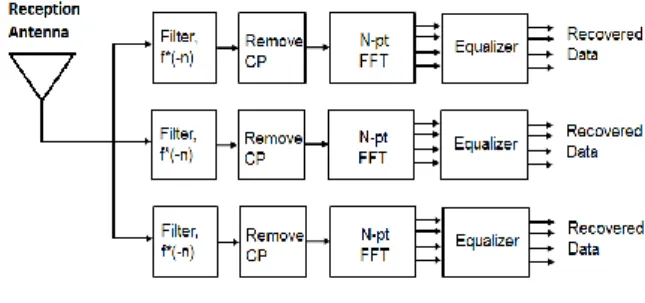
Figure 1 and Figure 2 show the basic transmitter and receiver structural design for F-OFDM respectively. The primary advantage of F-OFDM is that the space between the subcarriers in each of the sub-band can be different. It has been mentioned earlier that the each of these sub-bands, depending upon the services, can have different parameters.
Figure 1. F-OFDM Transmitter
The key to F-OFDM better performance is the filter, which can be seen in Figure 1 and 2. The filter design is discussed in the next section so as to provide a good insight about its importance. The transmitter structure of F-OFDM is not that different form CP-OFDM. The binary data stream is passed on to the transmitter where an N-point IFFT is performed. Next, the cyclic prefix is added between subcarriers to avoid inter symbol interference (ISI) and inter carrier interference (ICI). Before transmitting the signal, it is passed through a filter the reason for which is described earlier [11-13]. On the receiver side, an identical filter filters the incoming signal. In order to convert the signal back to its original form, the CP is removed and an N-point FFT is performed. The equalizer at the end equalizes the data symbols and finally converts it into bits again. The equalizer used can be of different types which include zero forcing (ZF Equalizer), MMSE (Minimum mean squared error Equalizer) and ML (Maximum likelihood Equalizer). The equalizer used is not the primary concern in this paper however for the while simulating F-OFDM, MMSE equalizer was used to get the results [12].
Figure 2. F-OFDM Receiver
It is worth mentioning that the sub-bands do not overlap each other and instead of a guard band, a guard tone is added between them. This guard tone is smaller than that of the guard band used in CP-OFDM and only utilizes 2% of the allocated spectrum which in the case of CP-OFDM was 10% [13].
2.2 Filter Design
Figure 3. Impulse Response of the Designed Filter Since the impulse response of the filter is infinitely long, a window is required to truncate the impulse response and allows smooth transition to zero. For smooth transition to zero, either Root-Raised cosine (RRC) window or hann window is used. For the purpose of simulation RRC window was used to truncate the impulse response of the filter.
3.
F-OFDM and CP-OFDM Comparison
As mentioned earlier, CP-OFDM and F-OFDM have same architecture except for a filter added to F-OFDM. The added filter enhances its performance in terms of spectral efficiency and aside from that, F-OFDM also has the ability to change parameters like sub-carrier spacing. Additionally, F-OFDM reduces the spectral consumed by the guard band and instead of a guard band a guard tone is added between sub-carriers [14, 15].
The power spectrum of both F-OFDM and OFDM is shown in Figure 4 and Figure 5 respectively. Using MATLAB plat form, both of these waveforms were simulated for a typical configuration used in 4G LTE systems with 600 sub-carriers each and a 15Khz sub-carrier spacing. Figure 4 and Figure 5 illustrate how F-OFDM provides better performance by enhanced suppression of side lobes in comparison to OFDM.
Figure 4. F-OFDM Power Spectrum Density
By increasing the length of CP more than that of the delay spread in OFDM, the forward ISI created due to multipath can be suppressed sophisticatedly. The duration of CP hence is chosen by keeping in mind these very phenomena. On the other hand, the filters used in F-OFDM cause long tail both backward and forward in time domain. Hence, in this scenario, the CP duration cannot be extended to cover the delay spread since it would lead to a high CP overhead.
Figure 5. CP-OFDM Power Spectrum Density
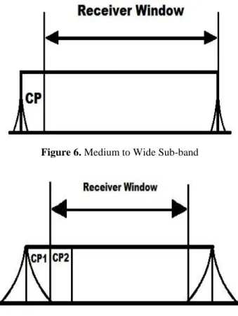
The size of the sub-band also plays a vital role here. If the sub-band has a small or a medium bandwidth, the tails of the filter are not a problem, since in that case the main lobe of the filter used would be considerably narrow thus avoiding long forward and backward tails of the filter. Figure 6 relates to the idea of short tails when the bandwidth of the sub-band is narrow. Since this situation occurs in most of the cases, filter tails can be considered negligible in most of the cases. However, in some scenarios, where the passband of the filter is extremely narrow, the main lobe of the band will widen and the tails associated with it would no longer be negligible. In this situation, the CP duration can be extended to cover up the main lobe of the filter and the slide the window to one-half of the main lobe. Figure 7 shows a visual representation of such a case where the extended CP can suppress the ISI created by the forward and backward tails of the filter but as mentioned earlier, this type of arrangement is only required with the sub-band is extremely narrow, which does not happen very often.
Figure 6. Medium to Wide Sub-band
4.
F-OFDM MIMO
In order to make the communication more robust and enhance the system performance, different diversity modes are used. These diversity modes include time diversity (diverse time slots and channel coding), frequency diversity (diverse channels and spread spectrum) and spatial diversity. Spatial diversity refers to the use of multiple antennas on either transmitter, receiver or both sides. Multiple input multiple output (MIMO) spatial diversity not only makes the system more robust but also enhances the data rates regardless of the communication system it is being applied to for example mobile radio services or wireless radio services. The comparison between F-OFDM and OFDM in earlier section reveals that F-OFDM has an edge over its predecessor and has better chances of being used for the upcoming generation of cellular communication system. The system architecture of F-OFDM has also been mentioned previously. Since spatial diversity (MIMO) can be used for both enhancing robustness and increasing data rates, implementing it might become mandatory for future networks.
Traditionally, a MIMO system consists of m transmit and n receive antennas. All of these antennas use the same channel and therefore every antenna does not only receive the direct component intended for it but also the indirect component from other antennas. This phenomenon can be represented using a matrix. By assuming a channel that is time-independent and is narrow band, a transmission matrix can be formulated that shows the direct and indirect component for each of the antenna. If the direct component from antenna 1 to 1 is the direct component and is represented by T11 then
the indirect component received by antenna 2 from antenna 1 can be written as T21. By following this, a transmission
matrix can be formed with order n x m. Figure 8 represents the transmission matrix formed by all the components of the transmit and receive antennas. The indirect and direct components of different antennas can also be seen in Figure 9. Since the channel through which the signal is propagating would certainly consist of noise, by introducing the noise element into the system and symbolizing transmit and receive vectors as x and y respectively, we can end up with the following transmission equation [16-17].
y = Hx + n (1)
In MIMO systems, the data that is to be transmitted is distributed into several data streams. The count of these data streams is always equal to or less than the number of antennas used at the transmitter. Thus, a system has two transmit antennas would be two or lesser data streams.
Figure 8. Transmission Matrix for m Transmit and n receive
antennas
The number of transmit and receive antennas in spatial diversity does not always have to be symmetric. A system can have asymmetric number of transmit and receive antenna depending upon the requirement. Thus, the system in which number of transmit antennas is more than the number of
receive antennas is known as transmit diversity whereas the system with higher number of receive antennas compared to the number of transmit antennas is called receive diversity [17].
Figure 9. Direct and Indirect Antenna Components
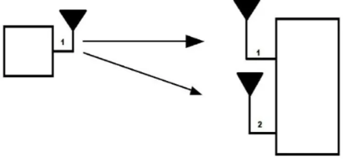
A system with receive diversity is more commonly known as the singe input multiple output (SIMO) system. Figure 10 illustrates a typical SIMO system with a single transmit and two receive antennas. This scenario is easy to implement since no spatial coding is needed and the receiver requires only two RF routes. Since the receiver has two different paths, it sees two different faded signals coming from the transmitter and by designing the receiver properly, the signal to noise ratio can be enhanced significantly [17, 18].
Figure 10. SIMO System
All the aforementioned system configurations including SISO, MIMO, SIMO and MISO are being simulated and tested in MATLAB and the outcomes are discussed briefly in section V. The results obtained from the simulation exclusively conclude the combined performance of MIMO and F-OFDM for different configurations and digital modulation schemes.
Figure 11. MISO System
5.
Simulation Results
Previous discussion regarding F-OFDM, OFDM and MIMO has shed some light on the fact that MIMO systems might be a necessity for the future mobile networks along with enhanced waveforms. In order to test the effect of F-OFDM MIMO, MATLAB platform has been used. The built in LTE functions and libraries make it easy to simulate the system with tunable parameters.
The primary parameters of the waveform were selected according to IEEE standards, which include 10MHz bandwidth with equivalent vehicular A channel model, 20Hz Doppler frequency, medium correlation, 75 dB filter side lobe attenuation, 512 filter length and 2.5 tone offset. Also, for 10MHz bandwidth, 50 Resource blocks are used with 12 subcarriers each and the duplex mode used is frequency division duplexing (FDD).
The results are plotted among bit error rate (BER) and signal to noise ratio (SNR). For different opted parameters of number of antennas at the transmitter and receiver and digital modulation schemes, the SNR is swept from zero to 5 and the plots acquired at the end show the effect.
First, the system is simulated for SISO system, which means that there is a single transmitting and a single receiving antenna. By keeping the number of antennas same, the result is repeated for QPSK, 16-QAM, 64-QAM and 256-QAM. Since the number of bits per subcarrier are least in QPSK and highest in 256-QAM, the system shows more robustness and achieves zero-bit error rate quicker in QPSK as compared to 256-QAM. Figure 12 shows how robustness of the system decreases with increase in data bits per sub-carrier. On the other hand, since higher number of data bits means higher data rate, higher order modulation can provide bigger data to be transmitted in one go. Thus, a compromise has to be made between robustness and data rate when using SISO systems.
The same test was performed for MIMO system. The number of transmit and receive antennas are increased in a symmetric order. The MIMO system is tested for two configurations, which are 2x2 and 4x4. As the number of transmit and receive antennas increase, the system shows better performance as compared to SISO system.
Figure 12. SISO system for different modulation schemes
performance
The diversity gain for MIMO is considerably enhanced. The modulation scheme selected for this test is 16-QAM and 64-QAM, which contain 4 and 6 bits per sub-carrier respectively. The results are shown in Figure 13. Compared to SISO system, as the number of antennas increase, the system shows better performance in terms of reducing bit error rate quickly as signal to noise ratio is increased.
Figure 13. MIMO 2x2 and 4x4 for 16-QAM and 64-QAM
Aside from this, for lower order modulation schemes like QPSK, even a smaller value of signal to noise ratio can provide satisfactory results. Thus, MIMO system can be of vital importance where signal to noise ratio cannot be increased above a certain threshold and high data rates are required.
By implementing SIMO configuration, the robustness of the system can be increased. Since the signal transmitted is from a single antenna and there are multiple antennas to receive the signal, each of the receiver antenna sees a faded copy of the same signal, which can be combined together at the receiver to enhance the system robustness. Figure 14 shows
the results with receiver diversity for 1x2 and 1x4 antenna
Figure 14. SIMO 1x2 and 1x4 for 16-QAM and 64-QAM Additionally, MISO configuration consists of single receiver and multiple transmit antenna. The same configuration which
is 2x1 and 4x1 has been implemented to test the effects of transmit diversity. This configuration divides the bit stream, which as mentioned earlier would be either equal to or less than the number of antenna being used at the transmitter.
Figure 15 shows an increase in performance as number of transmit antennas are increased but compared to Figure 14 the receive diversity has a better effect on diversity gain than transmit diversity. Although the performance enhancement lesser than the SIMO system, the fact that the MISO system has shown improvement cannot be ignored.
Figure 15. MISO system 2x1 and 4x1 for 16-QAM and
64-QAM
In the end, to analyze the effects of modulation schemes in details, the antenna configuration is set to 1x1, 2x2 and 4x4. The symmetric increase in the number of antenna is to analyze how the system responds for SISO and MIMO configuration for different modulation schemes. Figure 16, 17, 18 and 19show the effects of the three aforementioned configurations for QPSK, 16-QAM, 64-QAM and 256-QAM. By comparing Figures 16 through 19, it can be seen that as the modulation order increases, the performance enhancement is reduced. For QPSK, as the number of antenna increases, the effect is quite noticeable, but as the modulation is increased, the effect reduces and minor increase in performance can be seen as the configuration moves from 1x1 to 2x2 configuration but moving towards higher number of antennas i.e. 4x4, a perceptible increase can be seen.
Figure 16. QPSK Modulation with different Transmit and
Receive Antenna Configurations
Figure 17. 16-QAM Modulation with different Transmit and
Receive Antenna Configurations
Figure 18. 64-QAM Modulation with different Transmit and
Receive Antenna Configurations
Figure 19. 256-QAM Modulation with different Transmit
6.
Conclusions
The simulation results obtained in the previous section conclude that MIMO F-OFDM is capable of enhancing the performance of the system. The results show that increasing the number of antennas can increase robustness and is able to enhance data rates and support big data. Moreover, different modulation schemes can be adopted depending upon nature of service for maximum system performance. F-OFDM also provides tunable parameters like sub-carrier spacing, which was not possible in OFDM. For future technology where, mobile communication would not only be used for conventional communications but for machine type communication as well, the MIMO technique offers a reasonable way to carry out communication between the machines in an effective way. Since only minute modifications are required to upgrade the system to F-OFDM, this solution for future technology can also prove out to be cost effective. The need of lower latency and asynchronous connectivity is also achievable by F-OFDM. Hence, it can be concluded that F-OFDM can be a better choice for 5th generation of mobile communication systems.
References
[1] G. Wunder, P. Jung, M. Kasparick, T. Wild, F. Schaich, Y. Chen, S. Brink, I. Gaspar, N. Michailow, A. Festag, L. Mendes, N. Cassiau, D. Ktenas, M. Dryjanski, S. Pietrzyk, B. Eged, P. Vago, and F. Wiedmann, “5G NOW: non-orthogonal, asynchronous waveforms for future mobile applications, Communications Magazine,” IEEE, Vol. 52, No. 2, pp. 97105, Feb.2014.
[2] V. Vakilian, T. Wild, F. Schaich, S. ten Brink, and J.-F. Frigon, “Universal filtered multi-carrier technique for wireless systems beyond LTE,” in Proc. IEEE Globecom Workshops (GC Wkshps), pp. 223228, Dec 2013.
[3] J.-B. Dore, V. Berg, and D. Ktenas, “Channel estimation techniques for 5G cellular networks: FBMC and multiuser asynchronous fragmented spectrum scenario,” Transactions on Emerging Telecommunications Technologies, Vol. 26, No. 1, pp. 1530, 2015.
[4] J.-B. Dore, R. Gerzaguet, and D. Ktenas, “5G Cellular Networks with Relaxed Synchronization: Waveform Comparison and New Results,” in Proc. VTC Spring Workshop on 5G air interface, 2016.
[5] M. Matthe, D. Zhang, F. Schaich, T. Wild, R. Ahmed, and G. Fettweis, “A reduced complexity time-domain transmitter for UF-OFDM,” in Proc. IEEE 83rd Vehicular Technology Conference (VTC), pp. 15, May 2016.
[6] R. Gerzaguet, N. Bartzoudis, L. G. Baltar, V. Berg, J.-B. Dore, D. Ktenas, O. Font-Bach, X. Mestre, M. Payaro, M. Farber, and K. Roth, “The 5g candidate waveform race: a comparison of complexity and performance,” EURASIP Journal on Wireless Communications and Networking, Vol. 2017, No. 1, p. 13, 2017.
[7] D. Demmer, R. Gerzaguet, J.-B. Dore, D. Le Ruyet, and D. Ktenas, “Block-Filtered OFDM: an exhaustive waveform to overcome the stakes of future wireless technologies,” in Proc. IEEE ICC 2017 Wireless Communications Symposium (ICC17 WCS), Paris, France, May 2017.
[8] J. Faezah, K. Sabira, “Adaptive Modulation for OFDM
Systems,” International Journal of Communication Networks and Information Security, Vol. 1, No. 2, pp. 1-8, Aug. 2009. [9] E. M. E1-Bakary, O. Zahran, S.A. E1-Dolil, and F. E. Abd E1-
Samie, “Chaotic Maps: A Tool to Enhance the Performance of OFDM Systems,” International Journal of Communication Networks and Information Security, Vol. 1, No. 2, pp. 54-58, Aug. 2009.
[10]P. Siohan, C. Siclet, and N. Lacaille, “Analysis and design of OFDM/OQAM systems based on filterbank theory,” IEEE Transactions on Signal Processing, Vol. 50, No. 5, pp. 11701183, May 2002.
[11]X. Wang, T. Wild, and F. Schaich, “Filter optimization for Carrier frequency- and timing-offset in universal filtered multi-carrier systems,” in Proc. IEEE 81st Vehicular Technology Conference (VTC Spring), pp. 16, May 2015. [12]Abdoli J., Jia M. and Ma J., “Filtered OFDM: A New
Waveform for Future Wireless Systems,” 2015 IEEE 16th International Workshop on Signal Processing Advances in Wireless Communications (SPAWC), Stockholm, pp. 66-70, 2015.
[13]R1-162152. “OFDM based flexible waveform for 5G.” 3GPP TSG RANWG1 meeting 84bis. Huawei; HiSilicon, April 2016.
[14]W. H. Chin, F. Zhong, and R. Haines, “Emerging technologies and research challenges for 5G wireless networks,” IEEE Wireless Communication, Vol. 21, No. 2, pp. 106112, Apr. 2014.
[15]J. G. Andrews, S. Buzzi, W. Choi, S. V. Hanly, A. Lozano, A. C.K. Soong, and J. C. Zhang, “what will 5G be?” IEEE J. Select. Areas Communication, Vol. 32, No. 6, pp. 10651082, Jun. 2014.
[16]Bai, A. Alkhateeb, and R. Heath, “Coverage and capacity of millimeter wave cellular networks,” IEEE Communication. Magazine, Vol. 52, No. 9, pp. 7077, Sep. 2014.
[17]A. S ahin, I. Guvenc, and H. Arslan, “A survey on multicarrier communications: Prototype filters, lattice structures, and implementation aspects,” IEEE Communication. Surveys Tutorials, Vol. 16, No. 3, pp. 13121338, Aug.2014.
[18]P. Banelli, S. Buzzi, G. Colavolpe, A. Modenini, F. Rusek, and A.Ugolini, “Modulation formats and waveforms for 5G networks: Who will be the heir of OFDM?: An overview of alternative modulation schemes for improved spectral efficiency,” IEEE Signal Process. Mag., Vol. 31, No.6, pp. 8093, Nov. 2014.
[19]J. Santa, A. F. Gomez-Skarmeta, and M. S anchez-Artigas, “Architecture and evaluation of a unified V2V and V2I communication system based on cellular networks,” Elsevier Computer Communication, Vol. 31, No. 12, pp.28502861, Jul. 2008.
[20]B. E. Priyanto, H. Codina, S. Rene, T. B. Sorensen, and P. Mogensen, “Initial performance evaluation of DFT-spread OFDM based SC-FDMA for UTRA LTE uplink,” in Proc. IEEE Veh. Tech. Conf., Dublin, Ireland, pp. 31753179, Apr. 2007.
[21]A. Daher, E. H. Baghious, G. Burel, and E. Radoi, “Overlap-save and overlap-add filters: Optimal design and comparison,” IEEE Trans. Signal Process., Vol. 58, No. 6, pp. 30663075, Jun. 2010.
[22]G. Fettweis, M. Krondorf, and S. Bittner, “GFDM - generalized frequency division multiplexing,” in Proc. IEEE Veh. Tech. Conf., Barcelona, Spain, pp. 14, Apr. 2009. [23]F. Schaich, “Filterbank based multi carrier transmission
(FBMC) evolving OFDM: FBMC in the context of WiMAX,” in Proc. European Wireless Conf., Lucca, Italy, pp. 10511058, Apr. 2010.
[24]F. Schaich and T. Wild, “Waveform contenders for 5G OFDM vs. FBMC vs. UFMC,” in Proc. Int. Symp. Communication, Control Signal Process, Athens, Greece, pp. 457460, May 2014.