Quality of Service for Voice over IP
Version History
Quality of Service for Voice over IP discusses various quality of service (QoS) concepts and features that are applicable to voice—in particular, Voice over IP (VoIP). This document also provides high-level examples showing how to deploy these features in different network environments.
Quality of Service for Voice over IP contains the following sections:
• QoS for VoIP Overview, page 2
• Sufficient Bandwidth, page 2
• Packet Classification, page 3
• QoS Queueing Mechanisms, page 6
• Fragmentation and Interleaving, page 10
• Traffic Shaping, page 14
• IP RTP Header Compression, page 16
• Differentiated Services for VoIP, page 17
• Resource Reservation Protocol, page 20
• VoIP QoS over Leased Lines (Using PPP), page 32
• VoIP QoS over Frame Relay Networks, page 36
• VoIP QoS over ATM, page 39
• Related Documents, page 42
Version Number Date Notes
1 4/16/2001 This document was created. 2 5/15/2001 Incoporated editorial comments.
Quality of Service for Voice over IP QoS for VoIP Overview
QoS for VoIP Overview
For VoIP to be a realistic replacement for standard public switched telephone network (PSTN) telephony services, customers need to receive the same quality of voice transmission they receive with basic telephone services—meaning consistently high-quality voice transmissions. Like other real-time applications, VoIP is extremely bandwidth- and delay-sensitive. For VoIP transmissions to be
intelligible to the receiver, voice packets should not be dropped, excessively delayed, or suffer varying delay (otherwise known as jitter). For example, the following standards must be met:
• The default G.729 codec requires packet loss far less than 1 percent to avoid audible errors. Ideally, there should be no packet loss for VoIP.
• The ITU G.114 specification recommends less than 150 millisecond (ms) one-way end-to-end delay for high-quality real-time traffic such as voice. (For international calls, one-way delay up to 300 ms is acceptable, especially for satellite transmission. This one-way delay takes propagation delay into consideration—the time required for the signal to travel the distance.)
• Jitter buffers (used to compensate for varying delay) further add to the end-to-end delay, and are usually only effective on delay variations less than 100 ms. Jitter must therefore be minimized. VoIP can guarantee high-quality voice transmission only if the voice packets, for both the signaling and audio channel, are given priority over other kinds of network traffic. For VoIP to be deployed so that users receive an acceptable level of voice quality, VoIP traffic must be guaranteed certain compensating bandwidth, latency, and jitter requirements. QoS ensures that VoIP voice packets receive the
preferential treatment they require. In general, QoS provides better (and more predictable) network service by providing the following features:
• Supporting dedicated bandwidth
• Improving loss characteristics
• Avoiding and managing network congestion
• Shaping network traffic
• Setting traffic priorities across the network
Quality of Service for Voice over IP discusses various QoS concepts and features that are applicable to VoIP.
Sufficient Bandwidth
Before you consider applying any of the QoS features discussed in this document, you must first provision sufficient network bandwidth to support real-time voice traffic. For example, an 80-kbps G.711 VoIP call (64 kbps payload plus 16-kbps header) will be poor over a 64-kbps link because at least 16 kbps of the packets (which is 20 percent) will be dropped. This example also assumes that no other traffic is flowing over the link. After you provision sufficient bandwidth for voice traffic, you can take further steps to guarantee that voice packets have a certain percentage of the total bandwidth and get priority.
Quality of Service for Voice over IP
Packet Classification
Packet Classification
The basis for providing any QoS lies in the ability of a network device to identify and group specific packets. This identification process is called packet classification. After a packet has been classified, the packet needs to be marked by setting designated bits in the IP header. The following sections describe classification and marking:
• Packet Classification Overview
• Voice Dial Peers Classification and Marking Example
• Committed Access Rate Classification and Marking Example
• Policy-Based Routing Classification and Marking Example
• Modular QoS Command-Line Interface Classification and Marking Example
Packet Classification Overview
To guarantee bandwidth for VoIP packets, a network device must be able to identify VoIP packets in all the IP traffic flowing through it. Network devices use the source and destination IP address in the IP header or the source and destination User Datagram Protocol (UDP) port numbers in the UDP header to identify VoIP packets. This identification and grouping process is called classification and it is the basis for providing any QoS.
Besides the static classification methods involving Layer 3 or Layer 4 header information matching, you can use a mechanism such as Resource Reservation Protocol (RSVP) for dynamic classification. RSVP uses H.245 signaling packets to determine which UDP port the voice conversation will use. It then sets up dynamic access lists to identify VoIP traffic and places the traffic into a reserved queue. RSVP is discussed later in this document.
Packet classification can be processor-intensive, so it should occur as far out toward the edge of the network as possible. Because every hop still needs to make a determination on the treatment a packet should receive, you need to have a simpler, more efficient classification method in the network core. This simpler classification is achieved through marking or setting the type of service (ToS) byte in the IP header.
The three most significant bits of the ToS byte are called the IP Precedence bits. Most applications and vendors currently support setting and recognizing these three bits. Marking is evolving so that the six most significant bits of the ToS byte, called the Differentiated Services Code Point (DSCP), can be used to define differentiated services (DS) classes. DSCP is discussed later is this document.
After every hop in the network is able to classify and identify the VoIP packets (either through port address information or through the ToS byte), those hops can then provide each VoIP packet with the required QoS. At that point, you can configure special techniques to provide priority queueing to make sure that large data packets do not interfere with voice data transmission, and to reduce bandwidth requirements by compressing the 40-byte IP plus UDP plus RTP header to 2 to 4 bytes.
Classification and Marking
Classification is the process of identifying the class or group to which a packet belongs. Network devices use various match criteria to place traffic into a certain number of classes. Matches are based on the following criteria:
• The dial-peer voice voip global configuration command
Quality of Service for Voice over IP Packet Classification
• Protocol (such as URLs, stateful protocols, or Layer 4 protocol)
• Input port
• IP Precedence or DSCP
• Ethernet 802.1p class of service (CoS)
As mentioned, it can be processor-intensive if nodes must repeat classification based on access list matches. Therefore, nodes should mark packets as soon as they have identified and classified the VoIP packets. If a node can set the IP Precedence or DSCP bits in the ToS byte of the IP header as soon as it identifies traffic as being VoIP traffic, then all of the other nodes in the network can classify based on these bits.
Marking is the process of the node setting one of the following:
• Three IP Precedence bits in the IP ToS byte
• Six DSCP bits in the IP ToS byte
• Three MPLS Experimental (EXP) bits
• Three Ethernet 802.1p CoS bits
• One ATM cell loss probability (CLP) bit
In most IP networks, marking IP Precedence or DSCP should be sufficient to identify traffic as VoIP traffic.
Voice Dial Peers Classification and Marking Example
With Cisco VoIP gateways, you typically use voice dial peers to classify the VoIP packets and mark the IP Precedence bits. The following configuration example shows how to mark the IP Precedence bits:
Committed Access Rate Classification and Marking Example
Committed access rate (CAR) is an older technique that involves rate-limiting or policing traffic that matches certain criteria to an upper bound. CAR supports most of the matching mechanisms and allows IP Precedence or DSCP bits to be set differently depending on whether packets conform to or exceed a specified rate.
Configuration Example 1: Classification and Marking Using Dial Peers
dial-peer voice 100 voip destination-pattern 100 session target ipv4:10.10.10.2 ip precedence 5
In this example, any VoIP call that matches the dial-peer voice 100 voip
command will have all of its voice payload packets set with IP Precedence 5—meaning that the three most significant bits of the IP ToS byte are set to 101.
Quality of Service for Voice over IP
Packet Classification
In general, CAR is more useful for data packets than for voice packets. For example, all data traffic coming in on an Ethernet interface at less than 1 Mbps can be placed into IP Precedence Class 3, and any traffic exceeding the 1 Mbps rate can go into Class 1 or be dropped. Other nodes in the network can then treat the exceeding or nonconforming traffic marked with lower IP Precedence differently. All voice traffic should conform to the specified rate if it has been provisioned correctly.
The following configuration example shows how to use CAR to classify and mark VoIP packets:
Policy-Based Routing Classification and Marking Example
Policy-based routing (PBR) is another older feature that allows traffic to be routed based on source port or access list. It also can be used to classify and mark packets. A simple configuration example follows:
Modular QoS Command-Line Interface Classification and Marking Example
The recommended classification and marking method is the Modular QoS Command-Line Interface (Mod QoS CLI, or MQC) feature, a template-based configuration method that separates the
classification from the policy, allowing multiple QoS features to be configured together for multiple classes. You use a class map to classify traffic based on various match criteria and a policy map to
Configuration Example 2: Classification and Marking Using CAR
access-list 100 permit udp any any range 16384 32767 access-list 100 permit tcp any any eq 1720
!
interface Ethernet0/0
ip address 10.10.10.1 255.255.255.0 rate-limit input
access-group 100 1000000 8000 8000 conform-action set-prec-continue 5 exceed-action set-prec-continue 5
In this example, any traffic that matches access list 100 will be set with IP Precedence 5—meaning that the three most significant bits of the IP ToS byte are set to 101. Access list 100 here matches the common UDP ports used by VoIP and the H.323 signaling traffic to TCP port 1720.
Configuration Example 3: Classification and Marking Using PBR
access-list 100 permit udp any any range 16384 32767 access-list 100 permit tcp any any eq 1720
!
route-map classify_mark match ip address 100 set ip precedence 5 !
interface Ethernet0/0
ip address 10.10.10.1 255.255.255.0 ip policy route-map classify_mark
In this example, any traffic that matches access list 100 will be set with IP Precedence 5—meaning that the three most significant bits of the IP ToS byte are set to 101. Access list 100 here matches the common UDP ports used by VoIP and H.323 signaling traffic to TCP port 1720.
Quality of Service for Voice over IP QoS Queueing Mechanisms
determine what should happen to each class. Then you apply the policy to incoming or outgoing traffic on an interface using the service-policy interface configuration command. The following configuration example shows how to use Modular QoS to classify and mark packets:
QoS Queueing Mechanisms
After all traffic has been placed into QoS classes based on their QoS requirements, you need to provide bandwidth guarantees and priority servicing through an intelligent output queueing mechanism. This section describes queueing mechanisms and includes the following subsections:
• Low Latency Queueing
• LLQ Configuration Example
• Other QoS Queueing Mechanisms
Low Latency Queueing
A priority queue is required for VoIP. You can use any queueing mechanism that effectively gives VoIP high priority, but low latency queueing (LLQ) is recommended because it is flexible and easy to configure.
The most flexible queueing method that satisfies VoIP requirements is LLQ. LLQ uses the MQC configuration method to provide priority to certain classes and to provide guaranteed minimum bandwidth for other classes. During periods of congestion, the priority queue is policed at the configured rate so that the priority traffic does not monopolize all the available bandwidth. (If the
Configuration Example 4: Classification and Marking Using MQC
access-list 100 permit udp any any range 16384 32767 access-list 100 permit tcp any any eq 1720
!
class-map voip
match access-group 100 !
policy-map mqc class voip
set ip precedence 5
<<#various other QoS commands>> class class-default
set ip precedence 0
<<#various other QoS commands>> !
interface Ethernet0/0 service-policy input mqc
In this example, any traffic that matches access list 100 will be classified as class voip and set with IP Precedence 5—meaning that the three most significant bits of the IP TOS byte are set to 101. Access list 100 here matches the common UDP ports used by VoIP and H.323 signaling traffic to TCP port 1720. All other traffic is set with IP Precedence 0. The policy is called mqc and is applied to incoming traffic on Ethernet interface 0/0.
Quality of Service for Voice over IP
QoS Queueing Mechanisms
priority traffic monopolizes the bandwidth, it prevents bandwidth guarantees for other classes from being met.) If you provision LLQ correctly, the traffic going into the priority queue should never exceed the configured rate.
LLQ also allows queue depths to be specified to determine when the router should drop packets if too many packets are waiting in any particular class queue. There is also a class default that is used to determine treatment of all traffic not classified by a configured class. The class default can be configured with the fair-queue interface configuration command, which means that each unclassified flow will be given an approximately equal share of the remaining bandwidth. Figure 1 shows how LLQ works.
Figure 1 LLQ Operation
In Figure 1, all traffic going out of an interface or subinterface (for Frame Relay and ATM) is first classified using MQC. There are four classes: one high priority class, two guaranteed bandwidth classes, and a default class. The priority class traffic is placed into a priority queue and the guaranteed bandwidth class traffic is placed into reserved queues. The default class traffic can be given a reserved queue or can be placed in an unreserved default queue where each flow will get an approximately equal share of the unreserved and available bandwidth. The scheduler services the queues so that the priority queue traffic is output first unless it exceeds a configured priority bandwidth and this bandwidth is needed by a reserved queue (that is, there is congestion). The reserved queues are serviced according to their reserved bandwidth, which the scheduler uses to calculate a weight. The weight is used to determine how often a reserved queue is serviced and how many bytes are serviced at a time. The scheduler services are based on the weighted fair queueing (WFQ) algorithm, a discussion of which is beyond the scope of this document.
If the priority queue fills up because the transmission rate of priority traffic is higher than the configured priority bandwidth, the packets at the end of the priority queue will be dropped only if no more unreserved bandwidth is available. None of the reserved queues are restricted to the configured bandwidth if bandwidth is available. Packets violating the guaranteed bandwidth and priority are dropped only during periods of congestion. You must therefore provision the priority queue with enough bandwidth to handle all the VoIP traffic requiring priority servicing.
60595
Classification
Class priority Priority queue
Class 1 Reserved queue
Class 2 Reserved queue
Class default
Reserved queue or unreserved default queue
Quality of Service for Voice over IP QoS Queueing Mechanisms
LLQ Configuration Example
The following configuration example shows how to configure LLQ:
Configuration Example 5: LLQ
access-list 100 permit udp any any range 16384 32000 access-list 100 permit tcp any any eq 1720
access-list 101 permit tcp any any eq 80 access-list 102 permit tcp any any eq 23 !
class-map voip
match access-group 100 class-map data1
match protocol class-map data2
match access-group 102 !
policy-map llq class voip
priority 32 class data1
bandwidth 64 class data2
bandwidth 32 class class-default
fair-queue !
interface Serial1/0 bandwidth 256
service-policy output llq
In this example, any traffic that matches access list 100 will be classified as class voip (meaning voice traffic) and given high priority up to 32 kbps. Access list 100 matches the common UDP ports used by VoIP and H.323 signaling traffic to TCP port 1720. The class data1 command matches web traffic (TCP port 80 as seen in access list 101) and guarantees 64 kbps; the class data2 command matches Telnet traffic (TCP port 23 as seen in access list 102) and guarantees 32 kbps. The default class is configured to give an equal share of the remaining bandwidth to
unclassified flows. The policy is called llq, and it is applied on outgoing traffic on serial interface 1/0, which has a total bandwidth of 256 kbps.
Note By default, the total guaranteed bandwidth and priority bandwidth for all classes should be less than 75 percent of the interface bandwidth. You can modify this percentage by using the max-reserved bandwidth interface configuration command.
Quality of Service for Voice over IP
QoS Queueing Mechanisms
Other QoS Queueing Mechanisms
Several other queueing methods are available. For example, Modified Deficit Round Robin (MDRR) is a queueing mechanism available on the Cisco 12000 series Gigabit Switch Routers (GSRs) that allows bandwidth guarantees and priority servicing based on IP Precedence, DSCP, and MPLS EXP classes. MDRR supports one priority queue, seven reserved queues, and one multicast queue.
Once again, VoIP requires priority but there are data applications that cannot be starved and need bandwidth guarantees. You can use any queueing mechanism that effectively gives VoIP high priority, but we recommend LLQ.
Table 1 describes some of the available software queueing mechanisms.
Table 1 Software Queueing Mechanisms
Software Queueing
Mechanism Description Benefits Limitations
FIFO Packets arrive and leave the queue in exactly the same order.
Simple configuration and fast operation.
No priority servicing or bandwidth guarantees are possible.
WFQ A hashing algorithm places flows into separate queues where weights are used to determine how many packets are serviced at a time. You define weights by setting IP Precedence and DSCP values.
Simple configuration. Default on links less than 2 Mbps.
No priority servicing or bandwidth guarantees are possible.
Custom Queueing (CQ) Traffic is classified into multiple queues with configurable queue limits. The queue limits are calculated based on average packet size, maximum transmission unit (MTU), and the percentage of bandwidth to be allocated. Queue limits (in number of bytes) are dequeued for each queue, therefore providing the allocated bandwidth statistically.
Has been available for a few years and allows approximate bandwidth allocation for different queues.
No priority servicing is possible. Bandwidth guarantees are approximate, and there are a limited number of queues. Configuration is relatively difficult.
Priority Queueing (PQ) Traffic is classified into high, medium, normal, and low priority queues. The high priority traffic is serviced first, then medium priority traffic, followed by normal and low priority traffic.
Has been available for a few years and provides priority servicing.
Higher priority traffic can starve the lower priority queues of bandwidth. No bandwidth guarantees are possible.
Quality of Service for Voice over IP Fragmentation and Interleaving
Fragmentation and Interleaving
Because VoIP transmissions are extremely delay-sensitive, VoIP packets must be interleaved or inserted between data packet fragments. This section describes fragmentation and interleaving, and includes the following subsections:
• Fragmentation and Interleaving Overview
• MLP Link Fragmentation and Interleaving Example
• FRF.12 Fragmentation and Interleaving Example
Fragmentation and Interleaving Overview
Even if queueing is working at its best and prioritizing voice traffic, there are times when the priority queue is empty and a packet from another class is serviced. Packets from guaranteed bandwidth classes
Class-Based WFQ (CBWFQ) MQC is used to classify traffic. Classified traffic is placed into reserved bandwidth queues or a default unreserved queue. A scheduler services the queues based on weights so that the bandwidth
guarantees are honored.
Similar to LLQ except that there is no priority queue. Simple configuration and ability to provide bandwidth guarantees.
No priority servicing is possible.
Priority Queue WFQ (PQ-WFQ, also called IP RTP Priority)
A single interface command is used to provide priority servicing to all UDP packets destined to even port numbers within a specified range.
Simple, one command configuration. Provides priority servicing to RTP packets.
All other traffic is treated with WFQ. RTCP traffic is not prioritized. No guaranteed bandwidth capability.
LLQ (Previously called PQ-CBWFQ)
MQC is used to classify traffic. Classified traffic is placed into a priority queue, reserved bandwidth queues, or a default unreserved queue. A scheduler services the queues based on weights so that the priority traffic is sent first (up to a certain policed limit during congestion) and the bandwidth guarantees are met.
Simple configuration. Ability to provide priority to multiple classes of traffic and give upper bounds on priority bandwidth utilization. You can also configure bandwidth guaranteed classes and a default class.
No mechanism for providing multiple levels of priority yet—all priority traffic is sent through the same priority queue. Separate priority classes can have separate upper priority bandwidth bounds during congestion, but sharing of priority queue between applications may introduce jitter.
Table 1 Software Queueing Mechanisms (continued)
Software Queueing
Quality of Service for Voice over IP
Fragmentation and Interleaving
before being sent. If we assume that a VoIP packet will need to wait behind one data packet, and that the data packet can be, at most, equal in size to the MTU (1500 bytes for serial and 4470 bytes for high-speed serial interfaces), we can calculate the wait time based on link speed.
For example, for a link speed of 64 kbps and MTU size of 1500 bytes, we have:
Serialization delay = (1500 bytes * 8 bits/byte) / (64,000 bits/sec) = 187.5 ms
Therefore, a VoIP packet may need to wait up to 187.5 ms before it can be sent if it gets delayed behind a single 1500-byte packet on a 64-kbps link. VoIP packets usually are sent every 20 ms. With an end-to-end delay budget of 150 ms and strict jitter requirements, a gap of more than 180 ms is unacceptable.
You need a mechanism that ensures that the size of one transmission unit is less than 10 ms. Any packets that have more than 10-ms serialization delay need to be fragmented into 10-ms chunks. A 10-ms chunk or fragment is the number of bytes that can be sent over the link in 10 ms. You can calculate the size by using the link speed:
Fragmentation size = (0.01 seconds * 64,000 bps) / (8 bits/byte) = 80 bytes
It takes 10 ms to send an 80-byte packet or fragment over a 64-kbps link.
On low speed links where a 10-ms-sized packet is smaller than the MTU, fragmentation is required. Simple fragmentation is insufficient, though, because if the VoIP packet must wait behind all the fragments of a single large data packet, the VoIP packet still will be delayed beyond the end-to-end delay limit. The VoIP packet must be interleaved or inserted in between the data packet fragments. Figure 2 illustrates fragmentation and interleaving.
Figure 2 VoIP Packet Fragmentation and Interleaving
Serialization Delay = ---Frame Size Link Speed
214-ms Serialization Delay for 1500-Byte Frame at 56 kbps
Before
After using LFI Tools 1500-Byte Data Frame
Data Data Voice Data 60-Byte Voice
Quality of Service for Voice over IP Fragmentation and Interleaving
Table 2 shows recommended fragment sizes for various link speeds based on the 10-ms rule.
Table 2 Link Speed and Fragmentation Size
Note The packet fragmentation size should never be lower than the VoIP packet size. Also, you should never fragment VoIP packets—fragmenting VoIP packets can cause numerous call setup and quality problems.
Three link fragmentation and interleaving (LFI) mechanisms are available. Table 3 lists their benefits and limitations.
Link Speed (kbps) Fragmentation Size (Bytes)
56 70
64 80
128 160
256 320
512 640
768 960
1024 1280
1536 1920 (No fragmentation is required if the fragment size is larger than the link MTU size. For example, for a T1 link with a 1500-byte MTU, the fragment size is 1920 bytes; therefore, no fragmentation is required.)
Table 3 Link Speed and Fragmentation Size
LFI Mechanism Description Benefits Limitations
MTU Fragmentation with WFQ
Interface-level command to change MTU size or IP MTU size. Used to fragment large IP packets to specified MTU size. LFI uses WFQ to interleave real-time packets in between the fragments.
Simple configuration. Fragments are reassembled only by receiving application; therefore use of network is inefficient. Only IP packets with Don't Fragment (DF) bit not set can handle
fragmentation well. Highly-processor intensive. Not recommended.
Multilink Point-to-Point Protocol (MLP) Link Fragmentation and Interleaving (LFI)
On point-to-point serial links, MLP must first be configured, then a fragmentation size must be set in milliseconds.
Interleaving must also be enabled on the multilink interface.
Packets are fragmented on one end of link and reassembled at the other. Several links can be combined to act as a large virtual pipe.
Only available on links configured for PPP. Solutions for PPP over Frame Relay or PPP over ATM also are supported in Cisco IOS Release 12.1(5)T or later releases.
Quality of Service for Voice over IP
Fragmentation and Interleaving
MLP Link Fragmentation and Interleaving Example
The following configuration example shows how to configure fragmentation and interleaving using MLP LFI:
Frame Relay
Fragmentation (FRF.12)
On Frame Relay PVCs, the
frame-relay traffic-shaping
interface configuration
command must be enabled and a fragmentation size set under the map class.
Packets are fragmented on one end of PVC and reassembled at the other.
Only available on Frame Relay PVCs with the frame-relay traffic-shaping interface configuration command enabled.
Table 3 Link Speed and Fragmentation Size (continued)
LFI Mechanism Description Benefits Limitations
Configuration Example 6: MLP LFI
interface Serial1/0 bandwidth 256 encapsulation ppp no fair-queue ppp multilink multilink-group 1 !
interface Multilink1
ip address 10.1.1.1 255.255.255.252 bandwidth 256
ppp multilink
ppp multilink fragment-delay 10 ppp multilink interleave multilink-group 1
In this example, MLP LFI is configured with a fragmentation size of 10 ms, which is calculated based on the bandwidth configured for the multilink interface. Serial interface 1/0 is placed into multilink group 1 and therefore inherits the multilink configuration in the multilink 1 interface.
Quality of Service for Voice over IP Traffic Shaping
FRF.12 Fragmentation and Interleaving Example
The following configuration example shows how to configure fragmentation and interleaving using FRF.12:
Traffic Shaping
Traffic shaping is a QoS mechanism used to send traffic in short bursts at a configured transmission rate. It is most commonly used in Frame Relay environments where the interface clock rate is not the same as the guaranteed bandwidth or CIR. This section describes traffic shaping and includes the following subsections:
• Traffic Shaping Overview
• Frame Relay Traffic Shaping Example
Traffic Shaping Overview
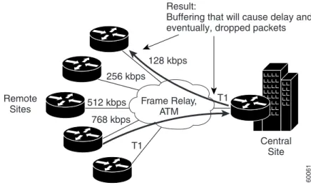
Frame Relay traffic shaping is the most common traffic shaping application in VoIP environments. Frame Relay scenarios usually have a hub and spoke network where the hub link speed is higher than any of the remote link speeds. In some cases, the sum of the remote link speeds is higher than the hub link speed, causing oversubscription. Without Frame Relay traffic shaping, the hub may try to send at higher rates than the remotes can receive traffic, causing the Frame Relay network to arbitrarily drop traffic. However, the remotes could all send at an aggregate rate that is higher than what the hub can receive, again causing the Frame Relay network to arbitrarily drop traffic. When we refer to the Frame Relay network, we mean the service provider (SP) network of WAN switches that provide the end-to-end PVC connectivity. Because the WAN SP cloud has no Layer 3 or above intelligence, it can
Configuration Example 7: Frame Relay Fragmentation (FRF.12) LFI
interface Serial 0/1 no ip address
encapsulation frame-relay frame-relay traffic-shaping !
interface Serial 0/1.64 point-to-point ip address 10.14.96.2 255.255.255.252 frame-relay interface-dlci 128
class voice !
map-class frame-relay voice frame-relay cir 256000 frame-relay fragment 320
In this example, Frame Relay traffic shaping is enabled on DLCI 128 and FRF.12 is configured with a fragmentation size of 320 bytes, which is 10 ms of the committed information rate (CIR). The fragmentation size should be 10 ms of the lower port speed at the endpoints of the PVC; this example assumes that the CIR and the lower port speed are the same: 256 kbps.
Quality of Service for Voice over IP
Traffic Shaping
drop VoIP traffic if contracts are violated. Therefore, you need to control transmission rates into a Frame Relay cloud so that you can control which packets get dropped and which packets receive priority servicing. Figure 3 shows an example of a typical Frame Relay network without traffic shaping.
Figure 3 Frame Relay Network
Frame Relay Traffic Shaping Example
The following configuration example shows how to configure Frame Relay traffic shaping:
Frame Relay, ATM
Central Site T1
T1 Remote
Sites
Result:
Buffering that will cause delay and, eventually, dropped packets
128 kbps 256 kbps
512 kbps 768 kbps
60061
Configuration Example 8: Frame Relay Traffic Shaping
interface Serial 0/1 no ip address
encapsulation frame-relay frame-relay traffic-shaping !
interface Serial 0/1.64 point-to-point ip address 10.14.96.2 255.255.255.252 frame-relay interface-dlci 128
class voice !
map-class frame-relay voice no frame-relay adaptive-shaping frame-relay cir 256000
frame-relay bc 2560 frame-relay mincir 256000
In this example, Frame Relay traffic shaping is enabled on the main serial interface 0/1 and DLCI 128 is placed into a voice shaping class. Map class voice sets up a CIR of 256000 bps and a committed burst rate (Bc) of 2560 bits. This configuration means that the router will send 2560 bits every 2560/256,000 seconds (10 ms) and queue any excess bursts. The minimum CIR is set to the same value as CIR, and adaptive shaping is disabled. The Frame Relay excess burst (Be) value is not set and therefore defaults to 0, preventing any bursting over CIR. This is the recommended configuration for traffic shaping when carrying VoIP.
Quality of Service for Voice over IP IP RTP Header Compression
IP RTP Header Compression
IP RTP header compression reduces the 40 byte IP+UDP+RTP header to 2 to 4 bytes, thereby reducing the bandwidth required per voice call on point-to-point links. The header is compressed at one end of the link and decompressed at the other end. Another standard name for this technique is cRTP, which stands for compressed RTP. Figure 4 shows the functionality of RTP header compression.
Figure 4 RTP Header Compression
To configure IP RTP header compression, you need to configure the ip rtp header-compression
command under the serial interface, or the frame-relay ip rtp header-compression command under the Frame Relay subinterface. You can also configure the ip rtp compression-connections interface configuration command to set a maximum number of flows that will be compressed. Because cRTP can be processor intensive, you need to limit the number of compressed flows to prevent router performance degradation. Compressed RTP is recommended on low speed links where bandwidth is scarce and there are few VoIP calls.
IP 20
UDP RTP IP Data
8 12
5
IP Data FTP SOL
1500 Byte -2.3% 256 Byte -13% VoIP
Efficiencies
20 Byte -240% Payload Packet Size
Reduction*
*Also -5ms Reduction in Serialization Delay at 64 kbps RTP
Compression
Transmit Queue
Output Hardware Configured
Queuing (e.g. WFQ, CQ) Traffic
Destined for Interface
Identify RTP Traffic
Compress RTP
Traffic (Video, Audio, etc.)
Classify
Non-RTP Traffic
Quality of Service for Voice over IP
Differentiated Services for VoIP
Differentiated Services for VoIP
The Differentiated Services (DS) architecture QoS model provides a scalable mechanism to classify packets into groups or classes that have similar QoS requirements. This section describes DS and includes the following subsections:
• DS and the DSCP (RFC 2474, RFC 2475) Overview
• Implementing DS for VoIP: Expedited Forwarding PHB (RFC 2598)
• DSCP Class-Based Marking Configuration Example
DS and the DSCP (RFC 2474, RFC 2475) Overview
The first IP networks were based on the best-effort service model, which meant that delay, jitter, packet loss, and bandwidth allocation were unpredictable. Today a large number of networks still follow this best-effort model and do not support enhanced applications that require some sort of service guarantee. Using the best-effort model, service providers have no means of offering service level agreements (SLAs) to their customers other than overprovisioning their network to deal with the busiest traffic hours. Enterprise customers and end users have no way of providing priority treatment or guaranteed bandwidth for VoIP. Traffic is treated on a simple, FIFO basis with no QoS enforcement.
The first architectural approach to providing end-to-end QoS required that the application signal its QoS resource requirements (such as bandwidth and guaranteed delay) to the network. In a VoIP scenario, this architectural approach meant that either the IP telephone or voice gateway needed to make QoS requests to every hop in the network so that end-to-end resources would be allocated. Every hop needed to maintain call state information to determine when to release the QoS resources for other calls and applications, and if enough resources were available, to accept calls with QoS guarantees. This method is called the Integrated Services QoS model. The most common implementation of Integrated Services uses Resource Reservation Protocol (RSVP). RSVP has some advantages, such as Call Admission Control (CAC), where a call can be rerouted by sending an appropriate signal to the originator if the network does not have the QoS resources available to support it. However, RSVP also suffers from some scalability issues; RSVP and those issues are discussed later in this document.
The DS architecture is the most widely deployed and supported QoS model today. It provides a scalable mechanism to classify packets into groups or classes that have similar QoS requirements and then gives these groups the required treatment at every hop in the network. The scalability comes from the fact that packets are classified at the edges of the DS “cloud” or region and marked appropriately so that the core routers in the cloud can provide QoS based simply on the DS class. The six most significant bits of the IP Type of Service (ToS) byte are used to specify the DS class; the Differentiated Services Code Point (DSCP) defines these six bits. The remaining two bits in the IP ToS byte are currently unused.
Quality of Service for Voice over IP Differentiated Services for VoIP
Figure 5 Differentiated Services Field Definition
Differentiated Services is described and defined in the following RFCs:
• RFC 2474, Definition of the Differentiated Service Field (DS Field) • RFC 2475, An Architecture for Differentiated Service
• RFC 2597, Assured Forwarding PHB Group • RFC 2598, An Expedited Forwarding PHB
RFC 2474 proposes a way of interpreting a field that has always been part of an IP packet. As mentioned previously in this document, the ToS field describes one entire byte (eight bits) of an IP packet. Precedence refers to the three most significant bits of the ToS byte; that is, [123]45678. (Occasionally the term ToS is used to refer to the next three bits: 123[456]78; however, in this document, to be consistent with the original RFC specification for the IP header (RFC 791), ToS refers to the entire set of eight bits.)
The first three bits of the DSCP are used as class selector bits; the class selector bits makes DSCP compatible with IP Precedence because IP Precedence uses the same three bits to determine class. Table 4 shows IP Precedence bit values mapped to DSCP.
Table 4 IP Precedence to DSCP Mapping
The next two bits are used to define drop preference. For example, if the traffic in Class 4 (the first three bits are 100) exceeds a certain contracted rate, the excess packets could be re-marked so that the drop
IP Precedence
IP Precedence Bit
Value DSCP Bits DSCP Class
5 101 101000 Expedited Forwarding
4 100 100000 Assured Forwarding 4
3 011 011000 Assured Forwarding 3
2 010 010000 Assured Forwarding 2
1 001 001000 Assured Forwarding 1
0 000 000000 Best Effort
0
Bits: 1 2 3 DSCP DS-Field
(for IPv4, ToS octet, and for IPv6, Traffic Class octet)
Class Selector Code Points
Currently Unused DSCP
RFC 2474
CU 4 5 6 7
Quality of Service for Voice over IP
Differentiated Services for VoIP
in Frame Relay and CLP-bit marking in ATM. These mechanisms allow the Layer 2 network to make intelligent drop decisions for nonconforming traffic during periods of congestion. DS allows similar operation over an IP network. The sixth bit must be set to 0 to indicate to the network devices that the classes have been set according to the DS standard.
The DS architecture defines a set of traffic conditioners that are used to limit traffic into a DS region and place it into appropriate DS classes. Meters, markers, shapers, and droppers are all traffic conditioners. Meters basically are policers, and class-based policing (which you configure using the
police policy-map configuration command under a class in Modular QoS CLI) is a DS-compliant implementation of a meter. You can use class-based marking to set the DSCP and class-based shaping as the shaper. Weighted Random Early Detect (WRED) is a dropper mechanism that is supported, but you should not invoke WRED on the VoIP class. Per hop behavior (PHB) describes what a DS class should experience in terms of loss, delay, and jitter. A PHB determines how bandwidth is allocated, how traffic is restricted, and how packets are dropped during congestion.
Three PHBs are defined in DS based on the forwarding behavior required:
• Best-effort class—Class selector bits set to 000
• Assured Forwarding PHB—Class selector bits set to 001, 010, 011, or 100
• Expedited Forwarding PHB—Class selector bits set to 101
The Assured Forwarding (AF) standard specifies four guaranteed bandwidth classes and describes the treatment each should receive. It also specifies drop preference levels, resulting in a total of 12 possible AF classes, as shown in Table 5.
Table 5 Possible Assured Forwarding Classes
You would most likely use Assured Forwarding classes for data traffic that does not require priority treatment and is largely TCP-based. Expedited Forwarding more closely matches VoIP QoS requirements.
Implementing DS for VoIP: Expedited Forwarding PHB (RFC 2598)
Expedited Forwarding (EF) is intended for delay-sensitive applications that require guaranteed bandwidth. An EF marking guarantees priority service by reserving a certain minimum amount of bandwidth that can be used for high priority traffic. In EF, the egress rate (or configured priority bandwidth) must be greater than or equal to the sum of the ingress rates, so that there is no congestion for packets marked EF. You implement EF behavior by using the strict priority queue in low latency queueing (LLQ). Constant bandwidth is guaranteed for traffic belonging to the EF class, but at the same time if there is congestion, nonconforming packets exceeding the specified priority rate are dropped to assure that packets in other queues belonging to different classes are not starved of bandwidth. The recommended DSCP value for EF is 101110 (46). The first three bits of this EF value correspond to IP
Drop Preference
Levels Class AF1 Class AF2 Class AF3 Class AF4
Low Drop Precedence
001010 010010 011010 100010
Medium Drop Precedence
001100 010100 011100 100100
High Drop Precedence
Quality of Service for Voice over IP Resource Reservation Protocol
Precedence 5, which is the recommended ip precedence dial-peer configuration command setting for VoIP traffic. Therefore, if IP devices in the network can recognize IP Precedence or DSCP for classification and marking purposes, you can provision end-to-end QoS.
DSCP Class-Based Marking Configuration Example
The DS architecture specifies how to classify, mark, police, and shape traffic entering a DS region and how to treat different classes at every hop in the DS region. At the DS edge, all IP packets are marked with the appropriate DSCP so that QoS can be provided based on the DSCP inside the DS region. The following configuration example shows how to configure DSCP marking at the edge using class-based marking:
All queueing and other QoS parameters now can be set to match on DSCP in the rest of the DS region. In the remaining sections of this document, we will match IP Precedence 5 traffic as VoIP and IP Precedence 3 traffic as HTTP (web traffic), with all other traffic going into the default class. Similarly, DSCP 46 could be used for VoIP and DSCP 26 for HTTP. We could use several other classification and marking mechanisms, but to maintain consistency and simplicity, we will use IP Precedence.
Resource Reservation Protocol
Resource Reservation Protocol (RSVP) is an implementation of the Integrated Services architecture for QoS (RFC 2205). When VoIP was introduced, RSVP was immediately seen as a key component that would provide admission control and QoS for VoIP flows. However, the way RSVP and H.323 were previously integrated provided neither admission control nor adequate QoS for voice flows. Several
Configuration Example 9: Class-Based Marking of DSCP
access-list 100 permit udp any any range 16384 32000 access-list 100 permit tcp any any eq 1720
access-list 101 permit tcp any any eq 80 !
class-map voip
match access-group 100 class-map webtraffic
match access-group 101 !
policy-map dscp_marking class voip
set ip dscp 46 #EF Class class webtraffic
set ip dscp 26 #AF Class !
interface Ethernet0/0
service-policy input dscp_marking
In this example, all traffic coming in on Ethernet interface 0/0 is inspected and classified based on the voip and webtraffic class maps. The policy-map global configurationcommand sets the DSCP on the voip class traffic to 46 (101110 for EF) and the webtraffic class traffic to 26 (011010 for AF3).
Quality of Service for Voice over IP
Resource Reservation Protocol
enhancements have been made to address these limitations, and RSVP can now be used to implement CAC and to signal a desired QoS that will provide good quality voice end-to-end, even in the presence of congestion.
In this section RSVP is described (in general), focusing on a particular subset of platforms, topologies, and protocols. We also assume that you are using H.323 as the session protocol for a VoIP
gateway-based network. This section includes the following subsections:
• RSVP Overview
• RSVP for CAC Overview
• Deploying CAC Based on RSVP
• Configuring Local Gateway Resources if CAC Fails
• Using RSVP with LLQ
• Deploying RSVP Support for LLQ
RSVP Overview
The initial implementation of RSVP for VoIP had two limitations. The first was that CAC could not be implemented with RSVP because the reservation process was not synchronized with the voice call signaling. A call would proceed even if the RSVP reservation had failed or had not been completed. The second limitation was that a successful RSVP reservation might not provide good voice quality during periods of network congestion. RSVP created a reserved queue-per-traffic flow within the WFQ system and relied on that system to guarantee a bounded delay. However, WFQ was unable in some cases to provide an acceptable bounded delay for voice. RSVP needed to be able to use the priority queue in LLQ to guarantee a bounded delay that would not affect voice quality. In addition, RSVP was not supported on ATM or on shaped Frame Relay PVCs.
You should deploy RSVP to improve VoIP QoS only where it can have a positive impact on quality and functionality. The benefits of using RSVP outweigh the costs (management, overhead, and performance impact) only where there is limited bandwidth and frequent network congestion. Some IP environments have enough bandwidth to guarantee the appropriate QoS without needing to implement CAC for every call.
The following four mechanisms were introduced in Cisco IOS software to handle resource-based CAC:
• PSTN fallback—This method relies on network probing to measure delay, jitter, and loss to estimate the potential voice impairment that the call will experience. (The potential impairment is called the Calculated Planning Impairment Factor (ICPIF) and is explained in ITU-T G.113.) With this mechanism, you can define several thresholds so that calls are rejected if an IP network is congested.
• CAC defined on local gateway resources such as CPU, memory, and number of calls—With this method, you can configure thresholds that trigger different actions, such as hairpin call, reject call, or play a message.
• Bandwidth management via the H.323 gatekeeper—In this method, you can configure a maximum amount of bandwidth that gatekeepers then allocate to calls.
• RSVP.
Quality of Service for Voice over IP Resource Reservation Protocol
RSVP for CAC Overview
Using RSVP for VoIP CAC requires the synchronization of the call setup signaling and the RSVP signaling. This synchronization guarantees that the called-party phone rings only after the resources for the call have been reserved. This synchronization also gives voice gateways the control of what action to take before the call setup moves to the alerting stage if the reservation fails or cannot be completed within a predefined period of time. A voice call will trigger two RSVP reservations because the reservation and admission control mechanisms provided by RSVP are unidirectional. Each voice gateway is responsible for initiating and maintaining one reservation toward the other voice gateway. CAC for a VoIP call fails if at least one of the reservations fails. Figure 6 shows the sequence of packets exchanged between the gateways during a call setup if RSVP is used for resource reservation.
Figure 6 Call Setup with RSVP Enabled
In Figure 6, an originating gateway (OGW) initiates a call toward a terminating gateway (TGW). The originating gateway sends an H.323 SETUP message to the terminating gateway to initiate the call. That SETUP message carries the QoS that the originating gateway considers acceptable for the call. The terminating gateway responds with an H.323 CALL PROCEEDING message. Both the originating gateway and the terminating gateway initiate a reservation request by sending an RSVP PATH message. The packet flows of both reservations are independent of each other unless one of them fails. The terminating gateway blocks the call setup process waiting for the reservation results. The terminating gateway controls the admission decision for the call and needs to be notified that the reservations in both directions were successful. The terminating gateway discovers that its reservation was successful when it receives the RSVP RESV message. The terminating gateway detects that the originating gateway reservation was successful when it receives an RSVP RESV CONFIRMATION message from
SETUP Call Setup Initiated
OGW TGW Reservation Initiated
Call Connected Normal Call Disconnect Initiated OGW TGW Reservation Teardown Initiated
OGW TGW Reservation Initiated
OGW TGW Reservation Teardown Initiated
OGW Originating Gateway TGW Terminating Gateway
H.323 Call Setup Signaling RSVP Reservation Initiated by TGW RSVP Reservation Initiated by OGW
OGW TGW
PATH
RESV RESV CONFIRMATION
RELEASE COMPLETE PATH TEAR
PATH TEAR CALL PROCEEDING
PATH
RESV
ALERTING
PATH TEAR PATH TEAR CONNECT
Quality of Service for Voice over IP
Resource Reservation Protocol
alerting state. A normal disconnect is initiated when an H.323 RELEASE COMPLETE message is sent after the call is connected. At that point, the gateways tear down their reservations by sending RSVP PATH TEAR and RESV TEAR messages.
If at least one RSVP reservation fails, you can configure a voice gateway to take the following actions:
• The voice gateway can report the call failure to the user or the switch that delivered the call.
• The call can be rerouted through another path.
• The call can be connected with best-effort QoS.
This last behavior is possible because the terminating gateway knows which QoS is acceptable for the call from its own configuration and the value included by the originating gateway in the H.323 SETUP message. If the terminating gateway and the originating gateway request a nonbest-effort QoS and at least one reservation fails, the call will proceed as best-effort only if the originating gateway and the terminating gateway are willing to accept best-effort service. Call release and call rerouting are possible if one of the two voice gateways will not accept best-effort service. If you configure the gateway to reject the call and report the failure, CAS trunks and analog lines generate a fast busy signal. On CCS PRI trunks, a Q.931 DISCONNECT message with a cause “QoS unavailable” (49) will be generated. Figure 7 shows the details of a call that is rejected because the reservation initiated from the terminating gateway failed.
Figure 7 Call Failing RSVP CAC Because of Terminating Gateway Reservation Failure
SETUP Call Setup Initiated
OGW TGW Reservation Initiated
Call Disconnect Initiated
OGW TGW Reservation Initiated
OGW Originating Gateway TGW Terminating Gateway
H.323 Call Setup Signaling RSVP Reservation Initiated by TGW RSVP Reservation Initiated by OGW
OGW TGW
PATH PATH
RESV TEAR RESV CONFIRMATION
RELEASE COMPLETE PATH TEAR CALL PROCEEDING
PATH
RESV
PATH TEAR PATH TEAR
RESV
OGW TGW Reservation Teardown Initiated
OGW TGW Reservation Teardown Initiated
Quality of Service for Voice over IP Resource Reservation Protocol
Deploying CAC Based on RSVP
As already mentioned, you should deploy RSVP to improve VoIP QoS only where it can have a positive impact on quality and functionality. The benefits of using RSVP outweigh the costs only where bandwidth is limited. We recommend using Cisco IOS Release 12.1(5)T or a later release if you want to implement CAC for VoIP using RSVP.
You need to complete the following three basic steps to configure CAC for VoIP calls using RSVP:
• Enable synchronization between RSVP and the call signaling. (This synchronization is enabled by default when Cisco IOS Release 12.1(5)T or a later release is running.
• Configure the voice gateways on both sides of the VoIP dial peers to request a particular QoS via RSVP.
• Enable RSVP and specify the maximum bandwidth on all links that are traversed by voice packets where congestion is likely to occur.
The following configuration example shows how to configure CAC for VoIP calls using RSVP:
Configuration Example 10: Deploying CAC Using RSVP
hostname LongBay !
isdn switch-type primary-ni call rsvp-sync
!
controller T1 1/0 framing esf linecode b8zs
pri-group timeslots 1-24 !
interface Ethernet0/0
ip address 10.0.152.254 255.255.255.0 !
interface Serial0/0 bandwidth 1536
ip address 10.10.1.1 255.255.255.0 encapsulation ppp
ip tcp header-compression iphc-format ip rtp header-compression iphc-format ip rsvp bandwidth 1152 24
!
interface Serial1/0:23 no ip address
no logging event link-status isdn switch-type primary-ni isdn incoming-voice voice no cdp enable
Quality of Service for Voice over IP
Resource Reservation Protocol
The default dial-peer configuration requests and accepts best-effort QoS for VoIP calls. This translates to the gateway not initiating an RSVP reservation for the call because IP provides best-effort service by default. The other two service alternatives are controlled-load or guaranteed-delay QoS. These two services require RSVP signaling; they are requested using the req-qos dial-peer configuration command. The acceptable QoS controls how strict or loose the CAC criteria should be; you configure the acceptable QoS controls by using the acc-qos dial-peer configuration command. We recommend that you configure the originating gateway and the terminating gateway to request and accept guaranteed delay.
Sometimes you can configure the implicit dial peer matched on a terminating gateway to request and accept best-effort QoS. This dial peer takes effect when there is not an explicit dial peer match.
Configuring Local Gateway Resources if CAC Fails
As mentioned earlier, you can configure a voice gateway to take different actions if admission control fails. The first alternative is to have the gateways signal the user or the switch that delivered the call with a fast busy signal or a disconnect cause. If the call was delivered to the gateway by an ISDN switch, you can tune the Q.931 disconnect cause to guarantee that the switch handles calls correctly. A “QoS unavailable” (49) cause is returned by default when an ISDN call fails CAC because of the requested and acceptable QoS configured. You can modify this cause with the isdn network-failure-cause
interface configuration command or isdn disconnect-cause interface configuration command. The current implementation of the isdn network-failure-cause command overrides the value configured using the isdn disconnect-cause command.
ip route 0.0.0.0 0.0.0.0 10.10.1.2 !
voice-port 1/0:23 !
dial-peer voice 100 pots destination-pattern 2... no digit-strip
direct-inward-dial port 1/0:23 !
dial-peer voice 300 voip destination-pattern 3... session target ipv4:10.77.39.129 req-qos guaranteed-delay
acc-qos guaranteed-delay !
line con 0 line aux 0 line vty 0 4 !
end
This example shows a complete voice gateway configuration that highlights the commands for configuring CAC using RSVP. The voice gateway can act as an originating gateway and terminating gateway with this configuration. We have not prioritized voice signaling in this example.
Quality of Service for Voice over IP Resource Reservation Protocol
The following configuration example shows how to configure local gateway resources if CAC fails by tuning the Q.931 Disconnect Cause:
A second option is to allow the gateway to reroute the call through another path. If the dial peer matched by the call is part of a hunt group, other dial peers in that group are tried according to the preference
dial-peer configuration command. This allows you to implement different types of call routing on the gateway that consider QoS across IP networks.
The following configuration example shows how to configure local gateway resources by rerouting calls on the gateway if CAC fails:
Configuration Example 11: Tuning the O.931 Disconnect Cause
!
interface Serial1/0:23 no ip address
no logging event link-status isdn switch-type primary-ni isdn network-failure-cause 42 isdn incoming-voice voice no cdp enable
!
In this example, the router sends a Q.931 DISCONNECT message with a “Switching Equipment Congestion” (42) cause when an ISDN call fails CAC on the VoIP leg.
Configuration Example 12: Call Rerouting on the Gateway
dial-peer voice 100 pots destination-pattern 2... no digit-strip
direct-inward-dial port 1/0:23 !
dial-peer voice 300 voip preference 0
destination-pattern 3... session target ipv4:10.77.39.129 req-qos guaranteed-delay
acc-qos guaranteed-delay !
dial-peer voice 400 voip preference 2
destination-pattern 3... session target ipv4:10.23.45.2 req-qos guaranteed-delay acc-qos guaranteed-delay !
dial-peer voice 500 pots preference 5
destination-pattern 3... no digit-strip
direct-inward-dial port 1/1:23 !
Quality of Service for Voice over IP
Resource Reservation Protocol
The third possibility, available in Cisco IOS releases later than 12.1(5)T, is to configure the gateways to proceed with the call even if RSVP reservations fail. This option, however, does not provide a major improvement over earlier Cisco IOS release functionality. The only benefit it provides is that, in case of a successful RSVP reservation, the call does not proceed until the reservation is established. As mentioned earlier, a call can fail admission control if at least one of the two RSVP reservations needed for the call fails. For each RSVP reservation, admission control is performed on all interfaces where you have enabled RSVP by using the ip rsvp bandwidth interface configuration command. You can configure two values with the ip rsvp bandwidth command: the maximum total reserved
bandwidth and the maximum bandwidth per reservation. The maximum total bandwidth is limited by default to no more than 75 percent of the total bandwidth of the interface. You can modify that limit with the max-reserved-bandwidth interface configuration command. Exceptions to the maximum total bandwidth limitation are Frame Relay and ATM PVCs. For Frame Relay PVCs, the maximum reservable bandwidth is the minimum CIR, or, if not configured, half of the CIR. For ATM PVCs, the maximum reservable bandwidth is 75 percent of the configured available bit rate output minimum cell rate, near real-time VBR output-SCR, or real-time VBR average rate, whichever is configured. The total bandwidth available for RSVP reservations may be lower if you have reserved bandwidth using CBWFQ or LLQ through MQC. A bandwidth manager makes sure that the interface or the PVC bandwidth is not oversubscribed during the router operation.
Note This check is not performed during router configuration.
You should configure the maximum bandwidth per reservation to be no lower than what the codec requires plus all other protocol overhead except the Layer 2 protocol overhead. Table 6 shows the lowest values that you can use for different codecs. Remember that these values do not account for the bandwidth savings introduced by cRTP or voice activity detection (VAD). The actual voice stream may use less bandwidth, but the system will use the worst-case bandwidth.
This example shows an implementation of call rerouting on the gateway. Calls to seven-digit numbers starting with digit 3 try two voice gateways first. Calls are routed through the PSTN via voice port 1/1:23 if the VoIP calls fails due to CAC or any other reason.
Configuration Example 12: Call Rerouting on the Gateway (continued)
Table 6 Bandwidth Reserved by RSVP per VoIP Call
Codec Reserved Bandwidth per VoIP Call (kbps)
G711alaw 80
G711ulaw 80
G723ar53 22
G723ar63 23
G723r53 22
G723r63 23
G726r16 32
G726r24 40
G726r32 48
Quality of Service for Voice over IP Resource Reservation Protocol
One consideration when deploying RSVP for VoIP is the impact of resource reservation on the postdial delay. Implementing VoIP CAC based on RSVP relies on a prompt confirmation or rejection of the requested reservation. The time taken to reserve resources adds to the postdial delay, which should be kept as low as possible in most cases. RSVP packets are carried inside IP datagrams and are unreliable by nature. If an RSVP packet is lost during the initial reservation setup, an RSVP refresh timer must expire before the lost packet is resent. Because this refresh timer typically is defined in tens of seconds, a scenario that may add a postdial delay is unacceptable for the user. The call rsvp-sync resv-timer
global configuration command lets you control the maximum amount of time that the terminating gateway waits for the result of RSVP reservation requests. The default value of this timer is 10 seconds; you can set it to a value from 1 to 60 seconds according to your expectation of postdial delay.
Using RSVP with LLQ
Flows requesting a particular QoS via RSVP can take advantage of the queueing alternatives available in LLQ, which has two major components: a strict priority queue (PQ) and a CBWFQ system. Earlier implementations of RSVP relied on WFQ to meet the QoS requirements for delay-sensitive traffic. A reserved queue with a low weight was created when the RSVP reservation was installed. However, WFQ could not meet the delay requirements of voice traffic, and voice calls using RSVP were not able to take advantage of the PQ available throughout LLQ.
In Cisco IOS Release 12.1(3)T and later releases, a priority profile based on traffic characteristics exists so that certain flows can take advantage of the strict PQ in LLQ. When a RSVP reservation request is received on an interface where you have enabled WFQ, the flow traffic specification (TSpec) is compared against the profile to decide if that flow should take advantage of the PQ or if a queue should be reserved on the WFQ system. The TSpec is the traffic description carried in RSVP messages. This traffic description is made in terms of a token bucket (token rate r, plus a bucket size b) and some additional parameters (peak rate p, minimum policed unit m, and maximum packet size M). The PQ profile is defined in terms of token rate, bucket size, and an optional peak rate to token rate ratio. Flow reservations with a TSpec that do not exceed those defined in the PQ profile will use the PQ. Those flows with a TSpec that exceeds at least one parameter defined in the profile will get a reserved queue in the WFQ system. The priority profile allows you to classify priority flows based on their traffic characteristics—not just on the transport protocol and port. Figure 8 shows the LLQ structure for an interface where traffic is classified into different queues using several methods, including RSVP.
G729br8 24
G729r8 24
GSMEFR 29
GSMFR 30
Table 6 Bandwidth Reserved by RSVP per VoIP Call (continued)
Quality of Service for Voice over IP
Resource Reservation Protocol
Figure 8 RSVP Support for LLQ on Point-to-Point Interfaces
Cisco IOS Release 12.1(5)T introduced RSVP support for LLQ on Frame Relay PVCs. In this case, each PVC has its own queueing structure with a PQ and a CBWFQ system. At the interface level, a FIFO queue is set up unless you have enabled FRF.12 fragmentation. In that case, a dual FIFO system is set up with a high priority queue and a low priority queue. The high priority queue receives the PQ traffic from all PVCs plus Layer 2 control traffic. The low priority queue receives all other traffic from all PVCs. Remember that Frame Relay traffic shaping (FRTS) is required for Frame Relay circuits whether FRF.12 fragmentation is enabled or not. FRTS provides the back-pressure mechanism to detect congestion per PVC. Support for ATM PVCs is available in Cisco IOS Release 12.2(1)T.
Deploying RSVP Support for LLQ
You enable RSVP support for LLQ by default for voice flows on interfaces where RSVP and WFQ are enabled. You need not explicitly configure priority queues for voice packets. You can configure a custom priority queue profile using the ip rsvp pq-profile global configuration command. Configuring the profile as ip rsvp pq-profile voice-like restores the default behavior. The default priority queue profile uses a token rate of 12,288 bytes per second (approximately 98 kbps), a bucket size of 592 bytes, and a peak rate equal to 110 percent of the token rate (13,516 bytes per second or approximately 108 kbps). These parameter values support all possible codec configurations on voice gateways running
IP RTP Priority Classification
RSVP
Class Priority
Class 1
Class 2
Class Default
Default Unreserved Classification
Reserved Queues
Priority Queue
Scheduler Non-Voice
Flow Voice Flow
Reserved Queues
Reserved Queues
Reserved Queues
Quality of Service for Voice over IP Resource Reservation Protocol
Cisco IOS software. A Cisco voice gateway configured to reserve resources via RSVP will infer the correct TSpec exclusively from the codec used on the dial peer. You cannot control TSpec values using the CLI and no other bandwidth-saving features (such as VAD) are taken into consideration. Some revisions of Microsoft NetMeeting for Windows 98 and Windows 2000 (which use RSVP) signal a bucket size in the TSpec that is not compatible with these defaults. This problem affects Microsoft NetMeeting for calls using codecs that require 32 kbps or more. In those cases, you need to create a custom profile to match the parameters signaled by Microsoft Windows.
The following configuration example shows how to configure RSVP support for LLQ on a Frame Relay circuit that has two PVCs:
One of the important implications of RSVP support for LLQ is that it lets you classify voice traffic based on its traffic characteristics rather than on the transport protocol (UDP) and port number (16384 through 32767). The proper operation of LLQ relies on the assumption that the priority queue is used
Configuration Example 13: RSVP Support for LLQ on Frame Relay PVCs
hostname LongBay !
isdn switch-type primary-ni call rsvp-sync
!
interface Serial0/0 bandwidth 1536 no ip address
encapsulation frame-relay no fair-queue
frame-relay traffic-shaping !
interface Serial0/0.1 point-to-point ip address 10.10.1.2 255.255.255.0 frame-relay interface-dlci 16 class VoIPoFR
ip rsvp bandwidth 48 24 !
interface Serial0/0.2 point-to-point ip address 10.10.2.2 255.255.255.0 frame-relay interface-dlci 17 class VoIPoFRip
rsvp bandwidth 48 24 !
ip rsvp pq-profile voice-like !
map-class frame-relay VoIPoFR no frame-relay adaptive-shaping frame-relay cir 64000
frame-relay bc 640 frame-relay mincir 64000 frame-relay fair-queue frame-relay fragment 80 !
In this example, WFQ is enabled on the PVCs and disabled on the physical interface. Each PVC has a priority queue for voice traffic. The physical interface has the dual-FIFO queue structure. FRTS is enabled and its parameters are defined in the VoIPoFR map class.