Corporate Headquarters
Cisco Systems, Inc. 170 West Tasman Drive San Jose, CA 95134-1706 USA
http://www.cisco.com Tel: 408 526-4000
800 553-NETS (6387) Fax: 408 526-4100
Cisco Cable Modem Termination System
Feature Guide
September 2004
THE SPECIFICATIONS AND INFORMATION REGARDING THE PRODUCTS IN THIS MANUAL ARE SUBJECT TO CHANGE WITHOUT NOTICE. ALL STATEMENTS, INFORMATION, AND RECOMMENDATIONS IN THIS MANUAL ARE BELIEVED TO BE ACCURATE BUT ARE PRESENTED WITHOUT WARRANTY OF ANY KIND, EXPRESS OR IMPLIED. USERS MUST TAKE FULL RESPONSIBILITY FOR THEIR APPLICATION OF ANY PRODUCTS. THE SOFTWARE LICENSE AND LIMITED WARRANTY FOR THE ACCOMPANYING PRODUCT ARE SET FORTH IN THE INFORMATION PACKET THAT SHIPPED WITH THE PRODUCT AND ARE INCORPORATED HEREIN BY THIS REFERENCE. IF YOU ARE UNABLE TO LOCATE THE SOFTWARE LICENSE OR LIMITED WARRANTY, CONTACT YOUR CISCO REPRESENTATIVE FOR A COPY.
The Cisco implementation of TCP header compression is an adaptation of a program developed by the University of California, Berkeley (UCB) as part of UCB’s public domain version of the UNIX operating system. All rights reserved. Copyright © 1981, Regents of the University of California.
NOTWITHSTANDING ANY OTHER WARRANTY HEREIN, ALL DOCUMENT FILES AND SOFTWARE OF THESE SUPPLIERS ARE PROVIDED “AS IS” WITH ALL FAULTS. CISCO AND THE ABOVE-NAMED SUPPLIERS DISCLAIM ALL WARRANTIES, EXPRESSED OR IMPLIED, INCLUDING, WITHOUT
LIMITATION, THOSE OF MERCHANTABILITY, FITNESS FOR A PARTICULAR PURPOSE AND NONINFRINGEMENT OR ARISING FROM A COURSE OF DEALING, USAGE, OR TRADE PRACTICE.
IN NO EVENT SHALL CISCO OR ITS SUPPLIERS BE LIABLE FOR ANY INDIRECT, SPECIAL, CONSEQUENTIAL, OR INCIDENTAL DAMAGES, INCLUDING, WITHOUT LIMITATION, LOST PROFITS OR LOSS OR DAMAGE TO DATA ARISING OUT OF THE USE OR INABILITY TO USE THIS MANUAL, EVEN IF CISCO OR ITS SUPPLIERS HAVE BEEN ADVISED OF THE POSSIBILITY OF SUCH DAMAGES.
CCSP, the Cisco Square Bridge logo, Cisco Unity, Follow Me Browsing, FormShare, and StackWise are trademarks of Cisco Systems, Inc.; Changing the Way We Work, Live, Play, and Learn, and iQuick Study are service marks of Cisco Systems, Inc.; and Aironet, ASIST, BPX, Catalyst, CCDA, CCDP, CCIE, CCIP, CCNA, CCNP, Cisco, the Cisco Certified Internetwork Expert logo, Cisco IOS, Cisco Press, Cisco Systems, Cisco Systems Capital, the Cisco Systems logo, Empowering the Internet Generation, Enterprise/Solver, EtherChannel, EtherFast, EtherSwitch, Fast Step, GigaDrive, GigaStack, HomeLink, Internet Quotient, IOS, IP/TV, iQ Expertise, the iQ logo, iQ Net Readiness Scorecard, LightStream, Linksys, MeetingPlace, MGX, the Networkers logo, Networking Academy, Network Registrar, Packet, PIX, Post-Routing, Pre-Routing, ProConnect, RateMUX, Registrar, ScriptShare, SlideCast, SMARTnet, StrataView Plus, SwitchProbe, TeleRouter, The Fastest Way to Increase Your Internet Quotient, TransPath, and VCO are registered trademarks of Cisco Systems, Inc. and/or its affiliates in the United States and certain other countries.
All other trademarks mentioned in this document or Website are the property of their respective owners. The use of the word partner does not imply a partnership relationship between Cisco and any other company. (0406R)
Cisco Cable Modem Termination System Feature Guide
Copyright © 2001-2004, Cisco Systems, Inc. All rights reserved.
iii
Cisco Cable Modem Termination System Feature Guide 0L-1467-04
C O N T E N T S
Preface
xvPurpose
xvAudience
xviDocument Organization
xviConventions
xviiiTerms and Acronyms
xixRelated Documentation
xixCisco uBR Series Documentation
xixAdditional Documentation Resources
xxObtaining Documentation
xxCisco.com
xxDocumentation CD-ROM
xxiOrdering Documentation
xxiDocumentation Feedback
xxiObtaining Technical Assistance
xxiCisco TAC Website
xxiiOpening a TAC Case
xxiiTAC Case Priority Definitions
xxiiObtaining Additional Publications and Information
xxiiiCable Interface Bundling for the Cisco CMTS
1Contents
2Prerequisites for Cable Bundling
2Restrictions for Cable Bundling
2Information About Cable Bundling
3Benefits
4Configuring Cable Bundling
4Monitoring Cable Interface Bundling
7Configuration Examples for Cable Interface Bundling
9Basic Cable Interface Bundling Example
9Additional References
10Related Documents
10Standards
11Contents
RFCs
12Technical Assistance
12Cable Monitor and Intercept Features for the Cisco CMTS
13Contents
14Prerequisites for Cable Monitor and Intercept
14Restrictions for Cable Monitor and Intercept
14Information About Cable Monitor and Intercept
14Overview of the cable interface Command
15Overview of the cable monitor Command
15Benefits
17How to Configure for Cable Intercept and Monitoring
17Configuring the cable intercept Command
17Configuring the cable monitor Command
19Monitoring the Cable Intercept and Monitor Features
21Displaying Information About Intercepted Traffic
21Displaying Information About Monitored Traffic
21DOCSIS Data Packets Example
22Timestamped Packets Example
22Configuration Examples
23Cable Intercept Configuration Example
23Cable Monitor Configuration Example (MAC Address)
23Cable Monitor Configuration Example (Ethernet, MAC-Layer, and DOCSIS-Data Packets)
24Additional References
24Related Documents
24Standards
25MIBs
25RFCs
25Technical Assistance
26DHCP, ToD, and TFTP Services for the Cisco CMTS
27Contents
28Prerequisites for DHCP, ToD, and TFTP Services
28Restrictions for DHCP, ToD, and TFTP Services
28Information About DHCP, ToD, and TFTP Services
29Feature Overview
29Contents
v
Cisco Cable Modem Termination System Feature Guide 0L-1467-04
External DHCP Servers
32Time-of-Day Server
33TFTP Server
35Benefits
36How to Configure DHCP, ToD, and TFTP Services
37Configuring DHCP Service
37Configuring Time-of-Day Service
43Configuring TFTP Service
45Configuring A Basic All-in-One Configuration (optional)
48Configuring an Advanced All-in-One Configuration (optional)
49Optimizing the Use of an External DHCP Server
49Configuration Examples
55DHCP Server Examples
55ToD Server Example
57TFTP Server Example
57Basic All-in-One Configuration Example
58Advanced All-in-One Configuration Example
62Additional References
68Related Documents
68Standards
70MIBs
71RFCs
71Technical Assistance
71Configuring DOCSIS 1.1 on the Cisco CMTS
73Contents
74Prerequisites for DOCSIS 1.1 Operations
74Restrictions for DOCSIS 1.1 Operations
75Information about DOCSIS 1.1
78Feature Overview
78DOCSIS 1.1 Quality of Service
80Benefits
86How to Configure the Cisco CMTS for DOCSIS 1.1 Operations
87Configuring Baseline Privacy Interface (optional)
88Downloading the DOCSIS Root Certificate to the CMTS (required)
91Adding a Manufacturer’s Certificate as a Trusted Certificate (optional)
94Contents
Enabling Concatenation (optional)
99Enabling DOCSIS Fragmentation (optional)
100Monitoring DOCSIS Operations
101Monitoring the DOCSIS Network
101Monitoring the RF Network and Cable Interfaces
107Monitoring BPI+ Operations
111Command Summary
114Configuration Examples for DOCSIS 1.1 Operations
115DOCSIS 1.1 Configuration for Cisco uBR7246VXR Router (without BPI+)
115DOCSIS 1.1 Configuration for Cisco uBR7246VXR Router (with BPI+)
117DOCSIS 1.1 Configuration for Cisco uBR10012 Router (with BPI+)
121Additional References
125Related Documents
125Standards
126MIBs
127RFCs
127Technical Assistance
127EtherChannel for the Cisco Cable Modem Termination System
129Contents
130Prerequisites for EtherChannel on the Cisco CMTS
130Restrictions for EtherChannel on the Cisco CMTS
131Information About EtherChannel on the Cisco CMTS
131Introduction to EtherChannel on the Cisco CMTS
131Cisco FastEtherChannel (FEC) and GigabitEtherChannel (GEC) on the Cisco uBR7246VXR Router
132Cisco GigabitEtherChannel (GEC) on the Cisco uBR10012 Router
132How to Configure EtherChannel on the Cisco CMTS
133Configuring FEC or GEC EtherChannel on the Cisco CMTS
133Verifying EtherChannel on the Cisco CMTS
136Configuration Examples for EtherChannel on the Cisco CMTS
136Additional References
140Related Documents
140Standards
142MIBs
142Technical Assistance
142Command Reference for EtherChannel on the Cisco CMTS
143Contents
vii
Cisco Cable Modem Termination System Feature Guide 0L-1467-04
Flap List Troubleshooting for the Cisco CMTS
151Contents
152Prerequisites for Flap List Troubleshooting
152Restrictions for Flap List Troubleshooting
152Information About Flap List Troubleshooting
152Feature Overview
153Information in the Flap List
153Cisco Cable Manager and Cisco Broadband Troubleshooter
154Benefits
155How to Configure Flap List Troubleshooting
155Configuring Flap List Operation Using the CLI (optional)
155Clearing the Flap List and Counters Using the CLI (optional)
157Enabling or Disabling Power Adjustment Using the CLI (optional)
158Configuring Flap List Operation Using SNMP (optional)
161Clearing the Flap List and Counters Using SNMP (optional)
161How to Monitor and Troubleshoot Using Flap Lists
162Displaying the Flap List Using the show cable flap-list Command
162Displaying the Flap List Using the show cable modem flap Command
166Displaying the Flap List Using SNMP
166Displaying Flap-List Information for Specific Cable Modems
167Troubleshooting Suggestions
169Configuration Examples for Flap List Troubleshooting
171Additional References
172Related Documents
172Standards
173MIBs
174RFCs
174Technical Assistance
174Internal DOCSIS Configuration File Generator for the Cisco CMTS
175Contents
175Prerequisites for the Internal DOCSIS Configuration File Generator
176Restrictions for the Internal DOCSIS Configuration File Generator
176Information About the Internal DOCSIS Configuration File Generator
177Contents
DOCSIS Configuration File Commands
178Benefits
179Related Features
179How to Use the Internal DOCSIS Configuration File Generator
179Creating and Configuring a DOCSIS Configuration File
180Specifying SNMP MIB Objects (Option 11)
184Specifying Vendor-Specific Information Fields (Option 43)
191Configuring the Router’s Onboard TFTP Server
194Configuration Examples for the Internal DOCSIS Configuration File Generator
196Platinum.cm
196Platinum.cm with BPI Enabled
196Disable.cm
196Configuration Files and DHCP Server Configuration
197Additional References
198Related Documents
198Standards
198MIBs
199RFCs
199Technical Assistance
199Maximum CPE and Host Parameters for the Cisco CMTS
201Contents
202Information About the MAX CPE and Host Parameters
202MAX CPE
203MAX CPE IP
203MAX Host
204Interoperation of the Maximum CPE Parameters
205Possible Conflicts Between Parameters
207Summary of CPE Address Control
208Benefits
208How to Configure the MAX CPE and Host Parameters
209Configuring the MAX CPE Parameter on the Cisco CMTS
209Configuring the MAX Hosts Parameter for a Cable Interface
211Configuring the MAX Hosts Parameter for a Particular Cable Modem
212Configuration Examples for the MAX CPE and Host Parameters
213Sample Outputs
213Additional References
215Contents
ix
Cisco Cable Modem Termination System Feature Guide 0L-1467-04
Standards
215MIBs
216Technical Assistance
216C H A P T E R 1
N+1 Redundancy for the Cisco Cable Modem Termination System
219Contents
221Prerequisites
221Restrictions and Limitations
222General N+1 Redundancy Restrictions and Limitations
222N+1 Redundancy Restrictions and Requirements for the Cisco uBR7246VXR Router
222N+1 Redundancy Restrictions and Requirements for the Cisco uBR10012 Router
223Information About N+1 Redundancy and the Cisco Universal Broadband CMTS
225The Components and Terminology of N+1 Redundancy
225IF Muting on the Cisco CMTS for non-SNMP-capable Upconverters
232Cisco RF Switch Configuration Tasks for N+1 Redundancy
235Configuring the Cisco RF Switch for N+1 Redundancy
235Creating Cisco RF Switch Module Bitmaps
238Cisco CMTS Configuration Tasks for N+1 Redundancy
241Preconfiguring HCCP Protect Interfaces for N+1 Redundancy
242Operating DHCP with the Cisco RF Switch
244Configuring HCCP Groups for N+1 Redundancy
245Enabling HCCP Protect Interfaces for N+1 Redundancy
247Maintaining Online Cable Modem Service When Removing HCCP Configuration from Working HCCP
Interfaces
248Switchover Testing Tasks for N+1 Redundancy
251Pre-testing System Check Procedures
251Switchover Testing Procedures
255Testing HCCP Groups with Manual Switchover
257Using the show cable modem Command After a Manual Switchover
258Configuration Examples for Cisco N+1 Redundancy
259Example: Cisco 3x10 RF Switch Modules in 8+1 Mode
260Example: Cisco 3x10 RF Switch Modules in 4+1 Mode
261Examples: Cisco 3x10 RF Switch with Cisco uBR10012 Chassis
269Example: Channel Switch Information from the Cisco uBR10012 Router
273Example: Cisco 3x10 RF Switch and Cisco uBR10012 Chassis
274Example: Cisco 3x10 RF Switches and Cisco uBR10012 Chassis
279Example: Cisco 3x10 RF Switches and uBR7246VXR Chassis
285Additional References
293Contents
Standards
294MIBs
294Technical Assistance
294Glossary
295Configuring PacketCable on the Cisco CMTS
299Contents
300Prerequisites for PacketCable Operations
300Restrictions for PacketCable Operations
300Information About PacketCable Operations
301Feature Overview
301PacketCable Network Components
301Dynamic Quality of Service
302Benefits
304How to Configure PacketCable Operations
306Enabling PacketCable Operation
306Disabling PacketCable Operation
307Configuring PacketCable Operation (Optional)
308Enabling Both PacketCable and Non-PacketCable UGS Service Flows
309Verifying PacketCable Configuration
311Configuring RADIUS Accounting for RKS Servers
311Monitoring and Maintaining PacketCable Operations
314Configuration Examples
314Typical PacketCable Configuration
315Additional References
318Related Documents
318Standards
319MIBs
320RFCs
320Technical Assistance
320Glossary
321Point-to-Point Protocol over Ethernet Termination on the Cisco CMTS
323Contents
324Prerequisites for PPPoE Termination
324Restrictions for PPPoE Termination
324Information About PPPoE Termination
325Feature Overview
325Contents
xi
Cisco Cable Modem Termination System Feature Guide 0L-1467-04
How to Configure the PPPoE Termination Feature
327Enabling VPDN Operations on the Cisco CMTS
327Configuring a Virtual Template on the Cisco CMTS
329Configuring a VPDN Group for PPPoE Sessions
332Configuring a VPDN Group for L2TP Tunnel Initiation on the Cisco CMTS
334Enabling PPPoE on a Cable Interface
336Configuring a Cisco Router as LNS
338Clearing PPPoE Sessions
340Enabling SNMP Traps for Active PPPoE Sessions
341Monitoring the PPPoE Termination Feature
342Configuration Examples for PPPoE Termination
342PPPoE Termination on a Cisco CMTS without L2TP Tunneling
343PPPoE Termination on a Cisco CMTS with L2TP Tunneling
344PPPoE Client Configuration on a Cisco Router
346PPPoE Configuration for the L2TP Network Server
346Additional References
348Related Documents
348Standards
348MIBs
349RFCs
349Technical Assistance
349Glossary
350Spectrum Management for the Cisco CMTS
353Contents
354Prerequisites for Spectrum Management
354Restrictions for Spectrum Management
356Cisco IOS Releases and Cable Interface Line Card Support
356Cisco uBR10012 Router and Cisco IOS Release 12.2(8)BC2 Support
357DOCSIS Cable Modem Test Analyzer
358Dynamic Upstream Modulation
358Fixed-Frequency Spectrum Groups with Advanced Spectrum Management
358Limitations on Upstream Modulation Parameters for PacketCable VoIP Calls
359HCCP 1+1 and N+1 Redundancy Support
359Intelligent and Advanced Spectrum Management Support
360Information About Spectrum Management
362Spectrum Management Measurements
363Upstream Signal Channel Overview
366Contents
Frequency Management Policy
368Guided and Scheduled Spectrum Management
370Intelligent and Advanced Hardware-Based Spectrum Management
376Benefits
378How to Configure Spectrum Management
382Guided and Scheduled Spectrum Management Configuration Tasks
382Intelligent and Advanced Spectrum Management Configuration Tasks
396Monitoring Spectrum Management
406Using CLI Commands
406Using SNMP
407Configuration Examples
411Upstream Traffic Shaping and Rate Limiting Examples
411Downstream Traffic Shaping and Rate Limiting Examples
414Spectrum Group and Combiner Group Examples
415Other Spectrum Management Configuration Examples
417Dynamic Upstream Modulation Examples
419Input Power Level Example
420Advanced Spectrum Management Configuration Examples
421Additional References
426Related Documents
426Standards
427MIBs
427RFCs
427Technical Assistance
428Telco Return for the Cisco CMTS
429Contents
429Prerequisites for Telco Return
430Restrictions for Telco Return
430Information about Telco Return
431Feature Overview
431DOCSIS Cable Plants
431Telco Return Operation
432Benefits
434How to Configure the Telco Return Feature
434Enabling Telco Return
434Configuring the Service Provider Descriptor Attributes
435Configuring the Registration IP Address (optional)
438Contents
xiii
Cisco Cable Modem Termination System Feature Guide 0L-1467-04
Configuration Examples
440Typical Telco Return Example
440Minimal Telco Return Example
441Minimal RADIUS Configuration
441Additional References
441Related Documents
441Standards
442MIBs
443RFCs
443Technical Assistance
443Time-of-Day Server for the Cisco CMTS
445Contents
446Prerequisites for the Time-of-Day Server
446Restrictions for the Time-of-Day Server
446Information About the Time-of-Day Server
446How to Configure the Time-of-Day Server on the Cisco CMTS
447Enabling the Time-of-Day Server
447Disabling the Time-of-Day Server
448Configuration Examples for the Time-of-Day Server
449Time-of-Day Server Configuration
449Additional References
450Related Documents
450Standards
450MIBs
451RFCs
451Technical Assistance
451xv
Cisco Cable Modem Termination System Feature Guide 0L-1467-04
Preface
This preface explains the objectives, intended audience, and organization of the Cisco Cable Modem Termination System Feature Guide for Cisco IOS Release 12.2(8)BC2 and earlier releases. This preface also defines this document’s conventions for conveying instructions and information.
• Purpose, page xv • Audience, page xvi
• Document Organization, page xvi • Conventions, page xviii
• Terms and Acronyms, page xix • Related Documentation, page xix • Obtaining Documentation, page xx • Obtaining Technical Assistance, page xxi
• Obtaining Additional Publications and Information, page xxiii
Purpose
This feature guide describes the software features contained in the Cisco Cable Modem Termination System (CMTS). Each chapter describes a feature; the supported releases; benefits; restrictions; any supported standards, MIBs, or RFCs; any prerequisites; and the configuration tasks and examples used to set up and implement the feature.
The feature guide replaces the Cisco IOS feature modules for cable that used to describe each CMTS feature, as well as feature content found in the Cisco uBR series software configuration guides. The guide represents ongoing documentation work—more and more of the CMTS features will be added into the guide until all the features have been included. As new CMTS features are introduced, they will be included in the feature guide. Cisco IOS feature modules for the CMTS will no longer be documented. Feature content in the Cisco uBR series software configuration guides will be phased out, and users will be referred to this feature guide.
The CMTS features are used by the Cisco uBR7100 series, the Cisco uBR7200 series, and the Cisco uBR10012 universal broadband routers.
Preface Audience
Audience
This guide is intended for CMTS system administrators, network administrators, and support engineers and technicians who configure, maintain, and troubleshoot the Cisco uBR7100 series, the
Cisco uBR7200 series, and the Cisco uBR10012 router.
All users should have some experience with configuring Cisco routers and using the Cisco IOS command-line interface (CLI). A basic familiarity with Data-over-Cable Service Interface
Specifications (DOCSIS) 1.0, DOCSIS 1.0+ quality of service (QoS) principles, and Simple Network Management Protocol (SNMP) is helpful.
Cable system administrators and support engineers should be acquainted with cable data networks and WAN communications protocols. Cable system technicians should be familiar with their cable plant’s base operating parameters and subscriber service offerings. Network administrators should be familiar with the principles of IP routing and subnetting; some of the advanced configurations also require an understanding of access lists and how to use them.
Document Organization
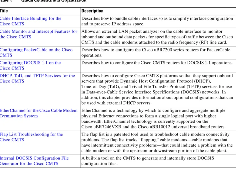
Table 1 summarizes the chapters in this guide.
Table 1 Guide Contents and Organization
Title Description
Cable Interface Bundling for the Cisco CMTS
Describes how to bundle cable interfaces so as to simplify interface configuration and to preserve IP address space.
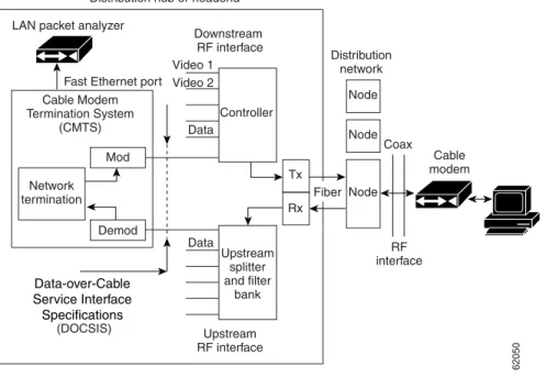
Cable Monitor and Intercept Features for the Cisco CMTS
Allows an external LAN packet analyzer on the cable interface to monitor inbound and outbound data packets for specific types of traffic between the Cisco CMTS and the cable modems attached to the radio frequency (RF) line card.
Configuring PacketCable on the Cisco CMTS
Describes how to configure the Cisco uBR7200 series routers for PacketCable operations.
Configuring DOCSIS 1.1 on the Cisco CMTS
Describes how to configure the Cisco CMTS routers for DOCSIS 1.1 operations.
DHCP, ToD, and TFTP Services for the Cisco CMTS
Describes how to configure Cisco CMTS platforms so that they support onboard servers that provide Dynamic Host Configuration Protocol (DHCP),
Time-of-Day (ToD), and Trivial File Transfer Protocol (TFTP) services for use in Data-over-Cable Service Interface Specifications (DOCSIS) networks. In addition, this chapter provides information about optional configurations that can be used with external DHCP servers.
EtherChannel for the Cisco Cable Modem Termination System
EtherChannel is a technology by which to configure and aggregate multiple physical Ethernet connections to form a single logical port with higher bandwidth. EtherChannel technology is currently supported on the
Cisco uBR7246VXR and the Cisco uBR10012 universal broadband routers.
Flap List Troubleshooting for the Cisco CMTS
The flap list is a patented tool used to troubleshoot cable modem connectivity problems. The flap list tracks “flapping” cable modems—cable modems that have intermittent connectivity problems—that could indicate a problem with the cable modem or with the upstream or downstream portion of the cable plant.
Internal DOCSIS Configuration File Generator for the Cisco CMTS
A built-in tool on the CMTS to generate and internally store DOCSIS configuration files.
xvii
Cisco Cable Modem Termination System Feature Guide 0L-1467-04
Preface
Document Organization
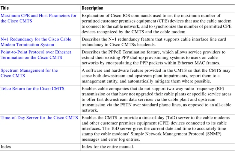
Maximum CPE and Host Parameters for the Cisco CMTS
Explanation of Cisco IOS commands used to set the maximum number of permitted customer premises equipment (CPE) devices that use the cable modem to connect to the cable network, and to synchronize the number of permitted CPE devices recognized by the CMTS and the cable modem.
N+1 Redundancy for the Cisco Cable Modem Termination System
Describes the N+1 redundancy feature that supports cable interface line card redundancy in Cisco CMTSs headends.
Point-to-Point Protocol over Ethernet Termination on the Cisco CMTS
Describes the PPPoE Termination feature, which allows service providers to extend their existing PPP dial-up provisioning systems to users on cable networks by encapsulating the PPP packets within Ethernet MAC frames.
Spectrum Management for the Cisco CMTS
A software and hardware feature provided in the CMTS so that the CMTS may sense both downstream and upstream plant impairments, report them to a management entity, and automatically mitigate them where possible.
Telco Return for the Cisco CMTS Enables cable companies that do not support two-way radio frequency (RF) transmission or that have not upgraded their cable plants or specific service areas to offer fast downstream data services via the cable plant and upstream
transmission via the PSTN over standard phone lines, as opposed to an all-cable network.
Time-of-Day Server for the Cisco CMTS Enables the CMTS to provide a time-of-day (ToD) server to the cable modems and other customer premises equipment (CPE) devices connected to its cable interfaces. The ToD server gives the current date and time to accurately time stamp the cable modems’ Simple Network Management Protocol (SNMP) messages and error log entries.
Index Index for the entire manual.
Table 1 Guide Contents and Organization
Preface Conventions
Conventions
This guide uses the following conventions for command syntax descriptions and textual emphasis:
Note This symbol means reader take note. Notes contain helpful suggestions or references to material not covered in the publication.
Tip This symbol means the following are useful tips.
Timesaver This symbol means the described action saves time. You can save time by performing the action described in the paragraph.
Caution This symbol means reader be careful. In this situation, you might do something that could result in equipment damage or loss of data.
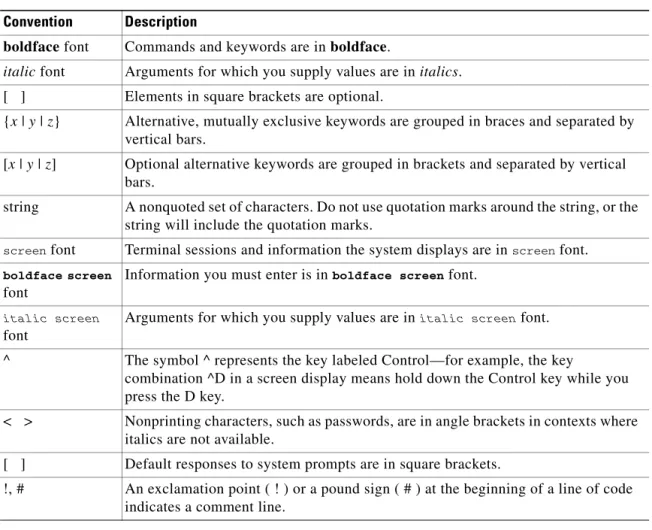
Table 2 Command Syntax and Emphasis Conventions
Convention Description
boldface font Commands and keywords are in boldface.
italic font Arguments for which you supply values are in italics. [ ] Elements in square brackets are optional.
{x | y | z} Alternative, mutually exclusive keywords are grouped in braces and separated by vertical bars.
[x | y | z] Optional alternative keywords are grouped in brackets and separated by vertical bars.
string A nonquoted set of characters. Do not use quotation marks around the string, or the string will include the quotation marks.
screen font Terminal sessions and information the system displays are in screen font.
boldface screen
font
Information you must enter is in boldface screen font.
italic screen
font
Arguments for which you supply values are in italic screen font.
^ The symbol ^ represents the key labeled Control—for example, the key
combination ^D in a screen display means hold down the Control key while you press the D key.
< > Nonprinting characters, such as passwords, are in angle brackets in contexts where italics are not available.
[ ] Default responses to system prompts are in square brackets.
!, # An exclamation point ( ! ) or a pound sign ( # ) at the beginning of a line of code indicates a comment line.
xix
Cisco Cable Modem Termination System Feature Guide 0L-1467-04
Preface
Terms and Acronyms
Terms and Acronyms
To fully understand the content of this guide, you should be familiar with the following terms and acronyms:
Note A complete list of terms and acronyms is available in the Dictionary of Cisco Internetworking Terms and Acronymsguide, available on Cisco.com and the Documentation CD-ROM.
• CoS—class of service
• CPE—customer premises equipment
• CRC—cyclic redundancy check
• CSU—channel service unit
• DCE—data communications equipment
• IPSec—IP Security Protocol
• MAC—Media Access Control
• MB—megabyte
• NVRAM—nonvolatile random-access memory
• OIR—online insertion and removal
• PPP—Point-to-Point Protocol
• QoS—quality of service
• RFI—radio frequency interference
• RIP—Routing Information Protocol
• SNMP—Simple Network Management Protocol
• TCP/IP—Transmission Control Protocol/Internet Protocol
• UBR—unspecified bit rate
• UDP—User Datagram Protocol
• UNI—User-Network Interface
• VPN—Virtual Private Network
Related Documentation
Cisco uBR Series Documentation
The procedures in this guide assume that site preparation and hardware setup are complete. Refer to the documents below as required for additional prerequisite information and reference.
Note If the hypertext link to any external document does not operate, you can access the desired document by typing or pasting the full document title in the Search field of the Cisco.com home page.
Click Go.
• Cisco uBR7100 Series Universal Broadband Routersdocumentation web page
• Cisco uBR7200 Series Universal Broadband Routers documentation web page
Preface Obtaining Documentation
Additional Documentation Resources
For detailed information on CMTS commands, syntax, and usage, refer to the
Cisco Broadband Cable Command Reference Guide.
For Cisco IOS software configuration information and support, refer to the configuration and command reference publications that pertain to your version of Cisco IOS software and hardware. Specifically, you should refer to the following publications:
• For procedures on configuring broadband routers using the Cisco command-line interface (CLI), refer to the Cisco IOS Multiservice Applications Configuration Guide, Release 12.1
• For information on setting up quality of service (QoS), refer to the Cisco IOS Quality of Service Solutions Configuration Guide, Release 12.2and Cisco IOS Quality of Service Solutions Command Reference, Release 12.2publications.
• For information on encryption, refer to the Cisco IOS Security Configuration Guide, Release 12.2
and the Cisco IOS Security Command Reference, Release 12.2publications.
• For information on interfaces, refer to the Cisco IOS Interface Configuration Guide, Release 12.2
and the Cisco IOS Interface Command Reference, Release 12.2publications.
• For information on IP, refer to the Network Protocols Configuration Guide, Part 1 and the
Network Protocols Command Reference, Part 1 publications.
• For information about configuring your Cisco networking device to function as a firewall and traffic filtering capabilities with access control lists, refer to the “Traffic Filtering and Firewalls” chapter of the Cisco IOS Security Configuration Guide, Release 12.2 on Cisco.com.
You can also refer to the Cisco IOS software release notes for the version of software you are using on your router. These Web pages on Cisco.com contain release notes for universal broadband routers:
• Release Notes for the Cisco uBR7100 Series Universal Broadband Routers • Release Notes for the Cisco uBR7200 Series Universal Broadband Routers • Release Notes for the Cisco uBR10012 Universal Broadband Router
Obtaining Documentation
Cisco provides several ways to obtain documentation, technical assistance, and other technical resources. These sections explain how to obtain technical information from Cisco Systems.
Cisco.com
You can access the most current Cisco documentation on the World Wide Web at this URL:
http://www.cisco.com/univercd/home/home.htm
You can access the Cisco website at this URL:
http://www.cisco.com
International Cisco websites can be accessed from this URL:
xxi
Cisco Cable Modem Termination System Feature Guide 0L-1467-04
Preface
Obtaining Technical Assistance
Documentation CD-ROM
Cisco documentation and additional literature are available in a Cisco Documentation CD-ROM package, which may have shipped with your product. The Documentation CD-ROM is updated regularly and may be more current than printed documentation. The CD-ROM package is available as a single unit or through an annual or quarterly subscription.
Registered Cisco.com users can order a single Documentation CD-ROM (product number DOC-CONDOCCD=) through the Cisco Ordering tool:
http://www.cisco.com/en/US/partner/ordering/ordering_place_order_ordering_tool_launch.html
All users can order annual or quarterly subscriptions through the online Subscription Store:
http://www.cisco.com/go/subscription
Ordering Documentation
You can find instructions for ordering documentation at this URL:
http://www.cisco.com/univercd/cc/td/doc/es_inpck/pdi.htm
You can order Cisco documentation in these ways:
• Registered Cisco.com users (Cisco direct customers) can order Cisco product documentation from the Networking Products MarketPlace:
http://www.cisco.com/en/US/partner/ordering/index.shtml
• Nonregistered Cisco.com users can order documentation through a local account representative by calling Cisco Systems Corporate Headquarters (California, USA.) at 408 526-7208 or, elsewhere in North America, by calling 800 553-NETS (6387).
Documentation Feedback
You can submit comments electronically on Cisco.com. On the Cisco Documentation home page, click
Feedback at the top of the page.
You can send your comments in e-mail to [email protected].
You can submit comments by using the response card (if present) behind the front cover of your document or by writing to the following address:
Cisco Systems
Attn: Customer Document Ordering 170 West Tasman Drive
San Jose, CA 95134-9883 We appreciate your comments.
Obtaining Technical Assistance
For all customers, partners, resellers, and distributors who hold valid Cisco service contracts, the Cisco Technical Assistance Center (TAC) provides 24-hour, award-winning technical support services, online and over the phone. Cisco.com features the Cisco TAC website as an online starting point for technical assistance.
Preface Obtaining Technical Assistance
Cisco TAC Website
The Cisco TAC website (http://www.cisco.com/tac) provides online documents and tools for
troubleshooting and resolving technical issues with Cisco products and technologies. The Cisco TAC website is available 24 hours a day, 365 days a year.
Accessing all the tools on the Cisco TAC website requires a Cisco.com user ID and password. If you have a valid service contract but do not have a login ID or password, register at this URL:
http://tools.cisco.com/RPF/register/register.do
Opening a TAC Case
The online TAC Case Open Tool (http://www.cisco.com/tac/caseopen) is the fastest way to open P3 and P4 cases. (Your network is minimally impaired or you require product information). After you describe your situation, the TAC Case Open Tool automatically recommends resources for an immediate solution. If your issue is not resolved using these recommendations, your case will be assigned to a Cisco TAC engineer.
For P1 or P2 cases (your production network is down or severely degraded) or if you do not have Internet access, contact Cisco TAC by telephone. Cisco TAC engineers are assigned immediately to P1 and P2 cases to help keep your business operations running smoothly.
To open a case by telephone, use one of the following numbers: Asia-Pacific: +61 2 8446 7411 (Australia: 1 800 805 227) EMEA: +32 2 704 55 55
USA: 1 800 553-2447
For a complete listing of Cisco TAC contacts, go to this URL:
http://www.cisco.com/warp/public/687/Directory/DirTAC.shtml
TAC Case Priority Definitions
To ensure that all cases are reported in a standard format, Cisco has established case priority definitions. Priority 1 (P1)—Your network is “down” or there is a critical impact to your business operations. You and Cisco will commit all necessary resources around the clock to resolve the situation.
Priority 2 (P2)—Operation of an existing network is severely degraded, or significant aspects of your business operation are negatively affected by inadequate performance of Cisco products. You and Cisco will commit full-time resources during normal business hours to resolve the situation.
Priority 3 (P3)—Operational performance of your network is impaired, but most business operations remain functional. You and Cisco will commit resources during normal business hours to restore service to satisfactory levels.
Priority 4 (P4)—You require information or assistance with Cisco product capabilities, installation, or configuration. There is little or no effect on your business operations.
xxiii
Cisco Cable Modem Termination System Feature Guide 0L-1467-04
Preface
Obtaining Additional Publications and Information
Obtaining Additional Publications and Information
Information about Cisco products, technologies, and network solutions is available from various online and printed sources.
• The Cisco Product Catalog describes the networking products offered by Cisco Systems, as well as ordering and customer support services. Access the Cisco Product Catalog at this URL:
http://www.cisco.com/en/US/products/products_catalog_links_launch.html
• Cisco Press publishes a wide range of networking publications. Cisco suggests these titles for new and experienced users: Internetworking Terms and Acronyms Dictionary, Internetworking
Technology Handbook, Internetworking Troubleshooting Guide, and the Internetworking Design Guide. For current Cisco Press titles and other information, go to Cisco Press online at this URL:
http://www.ciscopress.com
• Packet magazine is the Cisco quarterly publication that provides the latest networking trends, technology breakthroughs, and Cisco products and solutions to help industry professionals get the most from their networking investment. Included are networking deployment and troubleshooting tips, configuration examples, customer case studies, tutorials and training, certification information, and links to numerous in-depth online resources. You can access Packet magazine at this URL:
http://www.cisco.com/go/packet
• iQ Magazine is the Cisco bimonthly publication that delivers the latest information about Internet business strategies for executives. You can access iQ Magazine at this URL:
http://www.cisco.com/go/iqmagazine
• Internet Protocol Journal is a quarterly journal published by Cisco Systems for engineering professionals involved in designing, developing, and operating public and private internets and intranets. You can access the Internet Protocol Journal at this URL:
http://www.cisco.com/en/US/about/ac123/ac147/about_cisco_the_internet_protocol_journal.html • Training—Cisco offers world-class networking training. Current offerings in network training are
listed at this URL:
Preface Obtaining Additional Publications and Information
Corporate Headquarters:
Copyright © 2004 Cisco Systems, Inc. All rights reserved.
Cisco Systems, Inc., 170 West Tasman Drive, San Jose, CA 95134-1706 USA
Cable Interface Bundling for the Cisco CMTS
This document describes how to combine multiple cable interfaces in a Cisco Cable Modem Termination System (CMTS) universal broadband router into a single logical bundle, so as to conserve IP address space and simplify network management.
Feature History for Cable Interface Bundling
Finding Support Information for Platforms and Cisco IOS Software Images
Use Cisco Feature Navigator to find information about platform support and Cisco IOS software image support. Access Cisco Feature Navigator at http://www.cisco.com/go/fn. You must have an account on Cisco.com. If you do not have an account or have forgotten your username or password, click Cancel at the login dialog box and follow the instructions that appear.
Release Modification
12.0(7)XR This feature was introduced on Cisco uBR7200 series routers. 12.1(5)EC1 Support for this feature was added for Cisco uBR7100 series routers. 12.2(4)BC1 Support for this feature was added for Cisco uBR10012 routers. Support
for MPLS was also added for cable interface bundles on all Cisco CMTS routers.
12.1(20)EC This feature was enhanced, so that adding an interface as a slave interface automatically removes the following Layer 3 parameters, if they are configured on that interface: IP address, IP access group, and PIM configuration.
12.2(15)BC2 This feature was enhanced, so that adding an interface as a slave interface automatically removes the following Layer 3 parameters, if they are configured on that interface: IP address, IP helper address, IP access group, PIM configuration, and IP policy-based routing.
Also, creating subinterfaces on slave interfaces has been specifically prohibited. Previously, subinterfaces could be created on slave interfaces, although a warning message appeared advising users to remove the subinterface.
Cable Interface Bundling for the Cisco CMTS Contents
Contents
• Prerequisites for Cable Bundling, page 2 • Restrictions for Cable Bundling, page 2 • Information About Cable Bundling, page 3 • Configuring Cable Bundling, page 4
• Configuration Examples for Cable Interface Bundling, page 9 • Additional References, page 10
Prerequisites for Cable Bundling
• The cable interfaces that make up a bundle must all be in the same Cisco CMTS chassis router. You cannot bundle cable interfaces that are in separate routers.
• All cable interfaces must continue to be configured with the required DOCSIS upstream and downstream RF parameters. In addition, the master cable interface must be configured with all of the required Layer 3 parameters, such as the IP address and any helper addresses.
• When using both cable interface bundling and loadbalancing of downstreams, we recommend that each load balance group contain only downstreams in the same cable interface bundle group.
Restrictions for Cable Bundling
• Cable interface bundling is only supported on cable interfaces. It is not supported on other interfaces.
• Cable interface bundling can be used only in two-way cable installations. It is not supported for telco-return configurations.
• Each cable bundle must have exactly one interface that is designated as the master interface. All other cable interfaces in the bundle must be slave interfaces.
• All Layer 3 configurations, such as the IP address, access lists, DHCP relay, ARP handling, and source-verify checking, must be specified on the master interface. You cannot configure these parameters on the slave interfaces in the bundle. (However, you must still configure the DOCSIS upstream and downstream parameters on each interface.)
• If using subinterfaces, create the subinterfaces only on the master interface, and configure only the subinterfaces with the Layer 3 information, such as IP addresses and access lists. (Cable modems are associated only with the master subinterfaces and not the master main interface.)
Do not create subinterfaces on a slave interface. In Cisco IOS Release 12.2(15)BC2 and later releases, this is specifically prohibited. In prior releases, a warning message appeared when trying to create a subinterface on a slave interface, but the subinterface was still created.
• When you have configured a Cisco uBR7200 series router for both N+1 redundancy and cable interface bundling, the failure of one interface in a bundle causes the failover of the entire bundle. When you have configured a Cisco uBR10012 router for both N+1 redundancy and cable interface bundling, the failure of one cable interface results only in the failover of that particular interface.
• You must configure interface bundles only by using CLI commands. You cannot use MIB objects to configure cable interface bundles through SNMP sets.
Cable Interface Bundling for the Cisco CMTS
Information About Cable Bundling
3
Cisco IOS Release 12.3 BC • Multicast broadcasts have the following restrictions on bundled cable interfaces:
– For multicast addresses, the multicast MAC address points to the group of interfaces in the bundle that have received Internet Group Management Protocol (IGMP) joins.
– Since the multicast IP to MAC mapping is not unique, multiple multicast IP address share one entry in the MAC forwarding table.
• When using bundled cable interfaces on the Cisco 7200 series routers, the input packet counters for the master interface also include the packet counts for slave interfaces, except when using a Broadband Processing Engine (BPE) cable interface (such as the Cisco uBR-MC16U/X and Cisco uBR-MC28U/X). On BPE cards and on the Cisco uBR10012 router, the input counters for master and slave cable interfaces are not combined.
Information About Cable Bundling
Cable bundling allows multiple cable interfaces to use the same IP subnet, which allows service providers to conserve their limited IP address space. Using this feature allows several physical cable interfaces to be logically bundled together into a single, Layer 3 interface.
When interfaces are bundled together, one interface is designated as the master interface, and all of the other interfaces in the bundle become the slave interfaces. You then configure only the master interface with the Layer 3 information, such as IP addresses, access lists, cable source-verify, and so forth. This information is then propagated to the slave interfaces.
When cable modems come online any of the interfaces in a bundle, the Cisco CMTS router creates a MAC-based forwarding table that maps each cable modem (or customer premises equipment [CPE] device) with the actual physical cable interface that it is using. The router creates this table
automatically, and you do not need to reconfigure the cable modems or the routing tables on the Cisco CMTS router.
When the Cisco CMTS router receives a multicast packet on an interface bundle, it forwards it to all of the interfaces that are associated with this address in the bundle forwarding table. If the multicast MAC address is not in the bundle forwarding table, the router forwards the multicast traffic to all interfaces in the bundle.
Multicast MAC addresses are added to the bundle forwarding table in two ways:
• A static group is configured on the interface, in which case the multicast MAC address is added for all cable interfaces in the bundle. The MAC address is removed from the table when the static group configuration is removed.
• An interface receives an IGMP join request, in which case the multicast MAC address is added only for that particular interface. The MAC address is removed from the table when the interface receives an IGMP leave request.
You can add, remove, or shut down slave interfaces without affecting any of the other interfaces in the bundle. However, when you shut down or remove the master interface in a bundle, the slave interfaces remain in an online state, but no data packets are sent to any of these slave interfaces.
When the master interface is shut down, the active slave interfaces continue to receive packets, but the interfaces discard those packets as long as the master interface remains shut down. In this situation, cable modems that are connected to the slave interfaces remain online for a period of time, but they cannot renew their IP address with the DHCP server if the DHCP lease expires. Also, other cable modems cannot come online, because they cannot obtain an IP address or download a DOCSIS configuration file.
Cable Interface Bundling for the Cisco CMTS Configuring Cable Bundling
Benefits
• Cable interface bundling eliminates the need for an IP subnet for each cable interface by using only one IP subnet for each bundle of cable interfaces. This simplifies network management and conserves IP address space.
• Using cable bundling simplifies adding new cable interface line cards. When you add a new cable interface line card, you can simply assign the new interfaces to a cable bundle, without having to reassign IP addresses or create new subnets for the new set of interfaces.
• Cable bundling simplifies scalability and network management, because you can add a new cable interface line card to a bundle, and move cable modems to the new interfaces, without having to reconfigure the cable modems with new IP addresses or having to make any changes to the modem provisioning system. You can also move cable modems to other interfaces in the bundle at any time, without having to change their configuration. In particular, cable modems being assigned a static IP address can be inserted on any interface that is part of the bundle.
Configuring Cable Bundling
To create a cable bundle and to configure one cable interface to be its master interface, and one or more cable interfaces to be its slave interfaces, use the following procedure.
Prerequisites
• The master cable interface should be configured with the proper Layer 3 operational parameters, such as IP address, access lists, DHCP relay information, and so forth.
• Slave cable interfaces cannot be configured with an IP address, IP helper address, or other Layer 3 information. You must remove all Layer 3 configuration parameters from an interface before adding it to a bundle as a slave interface.
Note In Cisco IOS Release 12.2(15)BC2 and later releases, configuring a cable interface as a slave interface automatically removes Layer 3 information, such as the IP address, helper address, access group, Protocol Independent Multicast (PIM) configuration, and
policy-based routing.
• All cable interfaces must still be configured with the required DOCSIS RF upstream and downstream parameters.
Note Attempting to configure an IP address, IP helper address, or any other Layer 3 configuration on a slave interface in a bundle produces a warning message to remove the configuration. The Layer 3 configuration information must be removed from the slave interface to ensure proper operation of the interface bundle.
Restrictions
• Configuring a cable interface to be part of a bundle automatically shuts down the interface and reenables it. This automatically forces all cable modems on that interface to go offline and to reregister with the CMTS.
Cable Interface Bundling for the Cisco CMTS
Configuring Cable Bundling
5
Cisco IOS Release 12.3 BC SUMMARY STEPS
1. enable
2. configureterminal 3. interface cablex/y/z 4. cable bundlenmaster 5. ip addressip-address subnet
6. (any other Layer 3 configuration parameters)
7. interface cablex/y/z 8. no ip address 9. cable bundlen 10. end
DETAILED STEPS
Command or Action Purpose
Step 1 enable
Example:
Router> enable Router#
Enables privileged EXEC mode. Enter your password if prompted.
Step 2 configure terminal
Example:
Router# configure terminal Router(config)#
Enters global configuration mode.
Step 3 interface cable x/y/z
Example:
Router(config)# interface cable 5/1/0 Router(config-if)#
Enters interface configuration mode for the indicated cable interface.
Step 4 cable bundle n master Example:
Router(config-if)# cable bundle 1 master Router(config-if)#
Configures the cable interface to be the master interface for the specified bundle group.
• n = Bundle group number. The valid range is 1 to 255, with no default.
Step 5 ip address ip-address subnet
Example:
Router(config-if)# ip address 192.168.100.1 255.255.255.0
Router(config-if)#
Assigns the specified IP address and subnet mask to the master interface for the bundle.
Cable Interface Bundling for the Cisco CMTS Configuring Cable Bundling
Note To remove a cable interface from a bundle, use the no cable bundle command in interface configuration mode. Remember to reconfigure all of the Layer 3 IP information on the interface before attempting to bring cable modems back online the unbundled interface.
Step 6 <any other Layer 3 configuration parameters>
Example:
Router(config-if)# ip address 10.10.1.1 255.255.255.0 secondary
Router(config-if)#
(Optional) Configure the master interface with any other Layer 3 configuration parameters that are necessary.
Step 7 interface cable x/y/z
Example:
Router(config-if)# interface cable 5/1/1 Router(config-if)#
Enters interface configuration mode for the indicated cable interface.
Step 8 no ip address
Example:
Router(config-if)# no ip address Router(config-if)#
(Optional) Removes the IP address (if any) that was previously assigned to this cable interface. This command is optional but recommended, because the show ip interface brief command reports an interface as being not OK if its configuration does not include some form of the ip address command. Specifying no ip address corrects this.
Note In Cisco IOS Release 12.2(15)BC2 and later releases, configuring a cable interface as a slave interface automatically removes Layer 3 information, such as the IP address, IP helper address, IP access group, and IP policy-based routing.
Step 9 cable bundle n
Example:
Router(config-if)# cable bundle 1 Router(config-if)#
Configures the cable interface to be a slave bundle for the specified bundle group.
• n = Bundle group number. The valid range is 1 to 255, with no default.
Note When you configure a cable interface to be a slave interface in a cable bundle, the router automatically removes all Layer 3 and other generic configuration information from the interface (IP address, access lists, and so forth).
Note Repeat Step 7 and Step 9 for each cable interface that is to be a member of this bundle. Repeat Step 3 through
Step 9 for each cable bundle that is to be created on the router.
Step 10 end
Example:
Router(config-if)# end Router#
Exits interface configuration mode and returns to privileged EXEC mode.
Cable Interface Bundling for the Cisco CMTS
Configuring Cable Bundling
7
Cisco IOS Release 12.3 BC
Monitoring Cable Interface Bundling
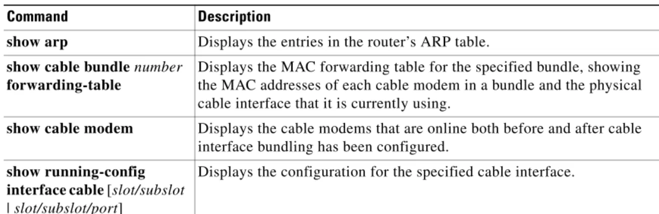
Table 1 lists the commands that are useful in monitoring the cable interface bundling feature:
show running-config interface cable Command
To display the bundles that are configured on a Cisco CMTS router, display the running configuration for each of the cable interfaces, using a command similar to the following:
show running-config interface cable slot/subslot
or
show running-config interface cable slot/subslot/port
For example, the following excerpt from a typical display shows that cable interface 3/0 is the master interface for bundle 1, and that cable interface 4/0 is a slave interface:
Router# show running-config interface cable 3/0
!
interface Cable3/0
ip address 10.13.0.1 255.255.0.0 secondary ip address 10.12.0.1 255.255.0.0
ip pim dense-mode
ip igmp static-group 225.2.2.2 no ip mroute-cache
cable spectrum-group 5
cable enable-trap cmonoff-notification cable max-hosts 2
cable bundle 1 master
...
cable helper-address 172.22.127.2 cable-modem cable helper-address 10.1.1.1
cable helper-address 10.2.2.2 host no keepalive
Router# show running-config interface cable 4/0
interface Cable4/0 no ip address cable bundle 1
...
Table 1 Commands to Monitor Cable Interface Bundling
Command Description
show arp Displays the entries in the router’s ARP table.
show cable bundle number
forwarding-table
Displays the MAC forwarding table for the specified bundle, showing the MAC addresses of each cable modem in a bundle and the physical cable interface that it is currently using.
show cable modem Displays the cable modems that are online both before and after cable interface bundling has been configured.
show running-config interface cable [slot/subslot
| slot/subslot/port]
Cable Interface Bundling for the Cisco CMTS Configuring Cable Bundling
cable helper-address 172.22.85.86 no keepalive
Router#
show cable bundle Command
Use the show cable bundle command to display the contents of the MAC forwarding information table for a specific cable interface bundle that has been configured on the Cisco CMTS router. This command has the following syntax:
show cable bundle n forwarding-table
The following example shows typical output for the show cable bundle command:
Router# show cable bundle 1 forwarding-table
MAC address Interface Flags Location link sublink 00c0.5e01.0203 Cable8/0/0 3 64E5BF60 0 64E5BE00 00c0.5e01.0203 Cable7/0/0 3 64E5BE00 0 0 00c0.5e01.0101 Cable8/0/0 3 64E5BEE0 0 64E5BE40 00c0.5e01.0101 Cable7/0/0 3 64E5BE40 0 0 00c0.a375.cc1c Cable8/0/0 1 64E5BEC0 0 0 00c0.0e01.a835 Cable8/0/0 1 64E5BEA0 0 0 00c0.0e01.a799 Cable8/0/0 1 64E5BDE0 0 0 00c0.0e01.a405 Cable8/0/0 1 64E5BF00 0 0 00c0.0e01.a5d1 Cable7/0/0 1 64E5BE20 0 0 00c0.0e01.a5d9 Cable8/0/0 1 64E5BE60 0 0 00c0.0e01.a5e1 Cable7/0/0 1 64E5BF40 0 0 00c0.0e01.a5f1 Cable7/0/0 1 64E5BE80 0 0 00c0.0eb4.0a41 Cable5/0/0 1 63704D1C 0 0 00c0.f03b.ed59 Cable6/1/0 1 6370427C 0 0 00c0.f03b.ed97 Cable6/1/0 1 63703F3C 0 0 00c0.0eb4.1373 Cable5/0/0 1 6370479C 0 0 00c0.f03b.edd3 Cable6/1/0 1 637042BC 0 0 00c0.7371.6df6 Cable5/0/0 1 63703DFC 0 0
Total = 18, sublink total = 2 Free = 1016, low_mark = 1016
Router#
The show bundle command displays the following information:
• MAC address—Identifies the MAC (hardware) address for a cable modem that is using an interface in the bundle.
• Interface—Identifies the cable interface slot and port number.
• Flag—Bitmask showing the current value of the flag byte for this bundle entry. The following bits can be set:
– Bit 0 (0x01) = Bundle is active.
– Bit 1 (0x02) = Bundle is a static multicast group.
Cable Interface Bundling for the Cisco CMTS
Configuration Examples for Cable Interface Bundling
9
Cisco IOS Release 12.3 BC
Configuration Examples for Cable Interface Bundling
This section contains the following sample configurations for the cable interface bundling feature:
• Basic Cable Interface Bundling Example, page 9
Basic Cable Interface Bundling Example
The following excerpt from a configuration file shows cable interface 4/0 being configured as the master interface for bundle 1, and interface 5/0 being configured as the first slave interface in the bundle. Note that all Layer 3 information is configured only on the master interface, but Layer 2 information, such as the DOCSIS RF configuration, is still configured on each interface.
!
interface Ethernet2/0
ip address 172.16.135.11 255.255.255.128 no ip mroute-cache
half-duplex !
interface Cable4/0
ip address 172.16.30.1 255.255.255.0 ip helper-address 172.16.135.20 no ip route-cache cef
no keepalive
cable bundle 1 master
cable downstream rate-limit token-bucket shaping cable downstream annex B
cable downstream modulation 64qam cable downstream interleave-depth 32 cable downstream frequency 555000000 cable upstream 0 frequency 40000000 cable upstream 0 power-level 0 no cable upstream 0 shutdown cable upstream 1 shutdown cable upstream 2 shutdown cable upstream 3 shutdown cable upstream 4 shutdown cable upstream 5 shutdown cable dhcp-giaddr policy !
interface Cable5/0 no ip address load-interval 30 no keepalive cable bundle 1
cable downstream rate-limit token-bucket shaping cable downstream annex B
cable downstream modulation 64qam cable downstream interleave-depth 32 cable downstream frequency 620000000 cable upstream 0 frequency 25008000 cable upstream 0 power-level 0
cable upstream 0 channel-width 1600000 3200000 no cable upstream 0 shutdown
no cable upstream 1 shutdown no cable upstream 2 shutdown cable upstream 3 shutdown cable upstream 4 shutdown cable upstream 5 shutdown