S o f t w a r e A r t i f a c t s
Steven P. Reiss
Department of Computer Science, Brown University, Providence, RI., [email protected]
Abstract. We have built a software development tool, CLIME, that uses constraints to ensure the consistency of the different artifacts associated with software. This approach to software development makes the environment re-sponsible for detecting most inconsistencies between software design, spec-ifications, documentation, source code, and test cases. It effectively defines the semantics of each software artifacts using constraints between it and the program or other artifacts. The tool provides facilities to ensure that the var-ious artifacts remain consistent as the software is written and evolves. This paper describes the techniques that underlie the tool, concentrating on the di-versity of artifacts the tool supports and on the definition and incremental maintenance of constraints between these artifacts.
1
Introduction
Software is multidimensional. Software systems consist of a variety of artifacts such as specifications, design diagrams and descriptions, source code, test cases, and documen-tation. Each of these dimensions describes only a limited part of the software — the ac-tual system is their composite.
Software evolution is the process whereby software changes to meet changing re-quirements, systems, or user needs. A major problem in software development today occurs when the different artifacts of a software system evolve at different rates. The source code will be updated to include all the necessary changes, but the specifications and design documents are often not modified to reflect these changes. Test cases may be thorough for the initial system but, in the absence of a proper development method-ology, tend to get overlooked with the addition of new features. Any user and developer is familiar with the manner in which documentation becomes out-of-date, and how im-plementation changes take a long time to percolate to the documentation. The result is that developers learn not to trust and thus not to use anything other than the source code, making software less reliable and much more difficult to understand and evolve.
We have designed and built CLIME, a tool that addresses these issues using a con-straint-based mechanism. The tool is designed to tell the developer when artifacts be-come unsynchronized and to indicate what needs to be changed or updated to achieve system-wide consistency. Our goal is to provide the developer with the information needed to ensure that all artifacts of a software system are consistent and complete be-fore a new version is released or a new change check in.
The preferred way of building such a system would be to have a formal definition for each of the artifacts using a common semantic representation, and then to ensure the consistency of the combined semantics. This works well for code where a precise defi-nition is possible. However, the diversity of the types of artifacts, the vagueness inher-ent in requireminher-ents, specifications, and even design artifacts, and the non-semantic na-ture of artifacts such as test cases, make this difficult if not impossible to do in any gen-eral and meaningful way.
Our tool takes a different approach, attempting to define less rigid but still formal semantics for each type of artifact. Rather than using a common representation, we de-fine the meaning of the artifact in terms of the constraints it imposes on other artifacts. This technique is surprisingly effective. For example, constraints can ensure that:
• Every class, field, and method that appears in the UML class diagram for the sys-tem must also appear in the source code and every public class from the source code appears in a UML class diagram that includes all its public methods and fields. This ensures that the UML and the source are consistent.
• Every public method, field, and class has associated javadoc documentation and the references in such documentation (e.g. see-also links, parameters, returns, and throws) are accurate. This ensures that the documentation is relevant even if its English description is not completely accurate.
• All procedures (or all basic blocks or all branches or all calls) are covered by at least one (working) test case that has been rerun since the last time the code it cov-ers has changed. The ensures the basic tenet of test cases (passing and coverage) and relates the test cases to the code.
• The sequence of calls shown in each UML interaction diagram is realizable in the code. This defines the semantics of the diagram in terms of possible program be-havior; other definitions (e.g. this sequence must occur in every execution) are also possible.
• Design patterns that are documented as part of the design exist in the code and persist through changes. The check for existence can include both structural and behavioral characteristics that have to appear in the code. This provides a practi-cal semantics for design patterns.
• The program source obeys a set of specified naming and usage conventions. This ensures that the source matches the semantics of any development guidelines. The tool works in phases. It first extracts relevant information from each of the soft-ware artifacts and stores it in a database. Next, it uses this stored information along with a description of the constraints among the artifacts to build the complete set of current constraints for the software system. Third, it uses the information in the database to test the validity of each of these constraints. Finally, it presents the results of these tests to the developers so that they can resolve any inconsistencies.
The key to the tool is to make this approach practical by providing accurate and timely information to the developer. Even a limited software project with a limited set of artifacts such as CLIME itself (about 65,000 lines), involves 10,000 constraints and a database containing 140Mb of data. Since most of the information does not change
frequently, it is essential that the tool work incrementally, i.e. that the database is main-tained incrementally and the set of constraints is updated and checked incrementally.
2
Related Work
Conceptually, the simplest approach to ensuring the consistency of different aspects of software is to combine them all within a single programming language. Several envi-ronments such as Xerox Cedar Mesa environment [19] and Common Lisp [18] have combined documentation with code. These efforts led to literate programming [2,11] and, more recently, the use of javadoc and its corresponding conventions. Environ-ments like Visual Studio combine code and user interface design. Proponents of UML propose writing complete systems within its framework, thus making it a programming language that combines design with code. Batory [1] lifts this idea to the level of mod-ules that encapsulate code, documentation and other dimensions; however, these must all compose through the same mechanism. This it not only very restrictive, it is unclear how, for instance, to compose text the same way we compose code. Other recent work looks at the impact of evolution of code but ignores the other dimensions [17].
There are a number of systems that check the consistency of single aspect of soft-ware. Lint [16] and successors such as CCEL [4] and LCLint [6] perform static check-ing of programs. Style checkers such as Parasoft’s tool suite or the checkstyle project perform style and convention checking of programs. Systems such as ViewIntegra [5] and xlinkit [10] have been used to check the consistency of UML diagrams. There are also a broad range of tools for doing test coverage, languages such as Eiffel that include checkable specifications in the code, and systems such as Flavors [3] do static checking of external specifications. The Eclipse and NetBeans environments provided language style and usage checking including checking documentation against the source.
The closest work of these to ours is the xlinkit approach [13] as applied to software engineering. Xlinkit provides the general ability to check the consistency of multiple XML documents. XML documents can either be specified directly or can be derived from other artifacts. The constraints use a set-based XML query language based on XPath and XLink. The current system is able to handle very large documents using a disk-based representation and is able to do limited incremental checking of constraints by looking at what portions of the XML tree have changed.
Our efforts differ in several respects. First, rather than using XML and XPath, we use a relational framework and SQL queries. This provides a more powerful query lan-guage and eliminates the need to treat large documents separate from small ones. Sec-ond, our system does incremental update of both the internal representation and the con-straints and does incremental constraint update at the constraint level rather than the rule level and thus can be used continuously throughout the development process. Xlin-kit would require that XML files be generated for any changes and does incremental up-date of constraints at the rule level. Third, our system handles a broader range or soft-ware artifacts, both static and dynamic. For example, we handle test cases and coverage, UML interaction diagrams, and behavioral specifications. Finally, our system works within existing programming environments, existing programming tools, and existing methodologies, and does so without requiring any action from the programmer.
3
Overview of the Approach
The overall tool consists of the components shown in Figure 1.. The components can be broken into two parts: the first part manages extracting the necessary information from the source artifacts while the second part uses this information to find, update, and dis-play information about the constraints.
The information is extracted through a set of abstractor tools. Most of these are in two parts. The first part takes the artifact, isolates the information that is relevant to a particular dimension, and then generates an XML file containing that information. The second part reads this XML file and then generates a second XML file consisting of commands to the database manager describing what tuples in what relations should be removed, inserted or updated.
There were several problems that had to be solved here. These included:
• What are the artifacts associated with a particular software project? To address this question we provided a Project Manager that lets the user define a project in terms of directories and files and then associate properties such as a classpath or compilation flags with the files.
• What information is required from the artifacts? This required an understanding of the often vague semantics of the artifacts as well as a good intuition for what types of constraints would be most effective. Here we have tried to err on the part of completeness, gathering as much information as possible from each artifact. • How to relate information across different abstractors, different dimensions, and
different times? This problem is two-fold. It first necessitates a consistent means of naming and identifying items so that names in one artifact can be related to
Software Artifacts Information Abstractors Database Manager Database Activity Monitor Updates Constraint Definitions Constraints Constraint Manager Presentation Manager User Output
Figure 1. The architecture of the CLIME tool.
Project
Manager Information Extraction
names in a second. Next it requires the database manager track and maintain iden-tities for tuples in the database
Having gathered information and filed it in the database, the tool must generate, maintain, and display the set of constraints that relate the artifacts. This work is done by two components, a constraint manager that is in charge of finding and updating con-straints and storing the resultant constraint information in another database, and a pre-sentation manager that uses this second database to provide appropriate feedback to the developer.
Again, there were several key problems that needed to be addressed in order to make this work efficiently and effectively. These included:
• How to define constraints? We chose to define a notion of metaconstraints that are instantiated based on objects in the database. The form of these constraints was dictated by this requirement and the need to associate a particular location in a source artifact with the constraint if it is violated. We found that most con-straints could be defined using formulas that related information in the database. • How to detect and check constraints? Given a particular form for a metacon-straint, we had to be able to quickly find the appropriate constraints and check whether they were satisfied. For formula-based metaconstraints, this is done by mapping the formula into a set of SQL queries.
• How to manage constraints incrementally? A complex software system can have large numbers of constraints. It was thus essential for scalability of the tool to be able to only check and update constraints that might be affected by the small set of changes that the developer makes as the system evolves. This was accom-plished by having the database manager generate a file describing the updates to the database and through the use of unique identifiers (UIDs) for database items.
4
Extracting Information
Information is extracted from the various software artifacts using an array of different tools, each of which is oriented to a particular type of artifact. The Activity Monitor component periodically determines when artifacts have changed and then automatically runs the appropriate Information Abstractors.
Changes are detected and updated at the file level. That is, when the activity moni-tor detects that the file representing a particular artifact has changed, it causes all the information in that artifact to be updated in the system. The file level seems to be the most appropriate for updating for such information because it is easy to detect when a file changes and because it is easiest to write abstractors that work on a whole file at once. While it is most common for only a small amount of information in the file to ac-tually change, detecting and abstracting only that information while maintaining con-sistency with the remainder of the database would have made all the extractors much more complex and slower. We opted instead to put the burden of determining the actual incremental update in the database manager and to keep the extractors fast and simple.
• Symbol table information. This includes information about the symbol type, data type, access information, and location of each definition, the location and defini-tion associated with each reference, and informadefini-tion about data types including the class hierarchy. It is generated by running a slightly modified version of IBM Jikes Java compiler that generates appropriate descriptions from the abstract syn-tax tree.
• Documentation information. This includes information about all Javadoc com-ments and the tags that they contain. It is generated by our own doclet that is in-voked by the standard javadoc program for each source file and which generates an XML description of all the available documentation-related information. • Semantic information. Language usage such as assignments inside conditionals,
unnecessary duplication of constant strings, or unterminated switch cases are best detected from the abstract syntax trees. This is done as part of our Jikes compiler extension.
• UML class diagrams. This includes information about classes, attributes, opera-tions, parameters, associaopera-tions, and generalizations. It is extracted directly from the XMI (standard XML for UML) representation which is either the native rep-resentation of the UML tool or, in the case of Rational Rose, using a conversion package that generates XMI from the native representation.
• UML sequence diagrams. This includes information about the signature and class of call points as well as the method bodies and order in which they occur. As in the case of UML class diagrams, this information is extracted from an XMI rep-resentation.
• Test cases. We assume that the developer is using Junit [9], a common Java test-ing package. The information extractor reads the compiled Java class files ustest-ing IBM’s JikesBT package [12]. It finds all classes that are instances of test group-ings and then identifies those functions that are actual test cases. It then patches the class files to capture flow information and runs Junit using the instrumented class files. The instrumentation calls routines that record each basic block entry, each call, as well as the entry and exit of the test cases. The result of running the instrumented code is an XML file for each test case that includes a description of the test case, the date and time it was run, whether it succeeded or failed, and cov-erage information for blocks, branches, functions, and calls.
• History information. This includes information about all the past versions of each version-managed software artifact. The information that is recorded includes ver-sion history, author, descriptions, and change information. This information is obtained by requesting complete CVS log information (assuming that the CVS version management system [7]is used) for each file.
• Static checks. We have a tool that does a full interprocedural flow analysis of a Java system and then checks if various dynamic contracts (such as proper use of Iterators or files) are maintained. The tool also generates information about dead code, possible dereferencing of null pointers, and specification violations. In addition to information that is abstracted directly from source artifacts, we found the need to have additional data that was implicitly but not explicitly part of the
soft-ware. Some of this information was needed to represent global information that is as-sumed by the developers, such as style rules describing naming conventions as well as language usage rules. Other information was needed because the set of formal artifacts that are used today is incomplete. Software development involves dimensions such as design patterns that are not directly represented by existing design tools or representa-tions. We are able to define relations in the database that represent design patterns (and have done so for several of the patterns in Gamma, et al. [8] and our previous work [14]), but we need to manually specify the instances of these patterns that occur in each particular software system for the database. Because our constraint framework is suffi-cient for checking that these patterns actually exist in the software, we see our manually entered definitions as a placeholder for what will eventually be a useful tool that would let developers specify and maintain a design-pattern-based description of their system.
Dealing with a variety of artifacts forced us to confront the problem of maintaining consistent global names. Since we wanted to relate information in one artifact with that in another, we needed to ensure that we could appropriately link equivalent references. In some cases, such as in UML diagrams, the programmer may provide only partial names, omitting the full package name and only providing the class name. However, in most cases, the abstraction tools have enough information to construct unique names for each package, class, method, field, scope, etc. We adopted a naming convention similar to that used in Java and required each abstraction tool to generate a field with this name for each appropriate entity.
The output of each of the abstractors is a set of commands to the database manager. The commands are of two forms. The first indicates that all data in a given database ta-ble that meet a given criterion are to be deleted. This is typically used to remove all the old information that is associated with a particular artifact when that artifact changes. The second form of command indicates a new tuple to be add to a particular table. By organizing the data independently of the information source, this greatly simplifies the actual database manager. Moreover, identifying deleted and added information explic-itly is necessary for incremental database update.
5
Storing and Updating Information
The database manager itself has four primary responsibilities. It first needs to pro-cess the commands that are provided by the information abstractors incrementally, add-ing and removadd-ing tuples in the database. Second, it needs to manage unique identifiers in order to maintain linkages among tables and between the data and the constraints. Third, it needs to maintain dynamic relations in the database. Finally it needs to gener-ate a file describing what has changed in the database so that constraint processing can also be done incrementally.
The commands to the database manager describe sets of tuples to be added and re-moved from each relation. Typically, they would indicate that all tuples that came from a particular artifact should be removed and then provide all new tuples for that artifact. This is true even if only a small change was made to the artifact. This presents two basic problems for an incremental framework. First, it means that the database manager would have to report a relatively large number of changes to the later constraint
man-ager even when only a small amount of data actually changed. Second, it makes track-ing unique identifiers more difficult. By solvtrack-ing these two problems, our database man-ager is able to handle incremental file-based updates efficiently.
To avoid these difficulties, the database manager attempts to intelligently update based on the information it has. Instead of deleting tuples outright, it reads all the tuples that would otherwise be deleted. It then compares each tuple to be added against those scheduled for deletion. If the new tuple is already in the database, it ignores both the request to remove and insert it. If the tuple exists in the database but some fields such as the line number have changed, it simply updates the changed fields. If the tuple is indeed new, it inserts it into the database. Finally, it removes all tuples that were not otherwise duplicated.
While maintaining the tuples in the relations, the database manager needs to man-age the assignment of unique identifiers (UIDs). Unique identifiers are associated with tuples in most of the tables of the database. They are used to provide links between ta-bles (such as the link between a symbol reference and its definition) and form the basis for later constraint management, where they are used to associate a particular constraint instance with the tuples in the database that caused it to be created and validated.
To support unique identifier management, the database system requires that any re-lation containing a UID field also specify the set of fields that characterize each tuple. This set of fields is then used to ensure that the same UID is used to represent the same object through updates. For example, in the relation describing source definitions, the UID is characterized by the name, the scope, the data type, and the type of symbol for the definition. When a tuple with a UID field is to be added to the database, the database manager checks if there is an existing UID assigned to the set of characteristic fields. If so, it will reuse this UID; if not a new UID will be created. The processing for UIDs takes advantage of the previously described incremental processing: it makes the as-sumption that any UID that would be reused will come from the set of tuples that are being deleted from the relation. This assumes that a UID will only be reused if the file it originally came from and it now derives from are the same. For Java, this is generally true for most symbols. Where it is not implicitly true, we ensure that the UID also de-pends on the original file by making the file part of the set of identifier fields.
A second part of UID management handled by the database involves tracking UIDs that are assigned by the various information abstractors and mapping these into global UIDs for the database. For example, the symbol table information abstractor assigns each definition that it generates a new local UID and links each reference to its defini-tion using it. These local identifiers are unique only with respect to the particular data file that is generated, are not unique globally, and do not correspond to existing or future global UIDs. The database manager handles local UIDs by tracking which fields con-tain UIDs and mapping the local UIDs, where given, into global UIDs that are generated using the previously cited rules for UID reuse.
Much of the information contained in a program or other artifact is hierarchical in nature, for example the class structure or scopes. Constraints based on such information often are interested not in the local hierarchy, but rather in the transitive closure of that hierarchy. Since transitive closure is not a normal database operation, our database
manager provides the facilities to automatically construct and update transitive rela-tions as the database changes. Here we are able to define a closure relation for any par-ticular database relation and have the new relation automatically recomputed when changes occur in the base relation. The database manager also provides for more tradi-tional query-based views as a means for simplifying queries and constraints.
The final task of the database manager is to generate an XML description of what has changed in the database. The description identifies which tuples are inserted, delet-ed, and updated for each table of the database. For tables that have UIDs associated with each tuple the information reported is the UIDs of modified tuples. For tables without associated UIDs, the only information to report is whether the table was changed.
6
Constraints and Constraint Maintenance
Given data about the different dimensions of a software system, the next portion of the tool defines, manages, and presents the constraints that ensure the different artifacts re-main consistent as the software evolves. The first step here involves defining what it means for two software artifacts to be consistent with one another. Typically, this will mean that a syntactic or semantic detail defined in one of the artifacts is represented ap-propriately in the other artifact. Our tool uses a constraint to reflect this association.
While it is not practical to have the developer explicitly define all the constraints that are needed to relate the various artifacts, it is possible to define rules whereby such constraints can be generated. These rules are what we call metaconstraints [15].
Meta-constraints have the form . Here S is a relation in the database and
x represents a tuple of that relation. This tuple is the source of the constraint. We require that any relation used as the source of the constraint have an associated UID field. This lets us easily identify the source for a constraint and to detect, based on the update file from the database manager, when we might have to check for new constraint instances (if new tuples are added to the relation S), check the continued appropriateness of con-straints (when tuples are updated in S), or remove existing concon-straints (when the source tuple for a constraint is removed from S).
The second part of the constraint definition, ϕ(x), indicates the conditions under which the constraint is applicable, while the third part, Θ(x), is a qualified predicate the specifies the conditions the constraint must meet. Both of these are arbitrary predicates defined over tables in the database. Variables ranging over the tables can be defined us-ing FORALL, EXISTS, NOTALL, NOTEXISTS, and UNIQUE, operators. Each such variable is meant to represent a tuple. Fields of that tuple can then be accessed via a FIELD operator. The predicates can also include comparisons, string matching, arith-metic and string operators, and Boolean operations. The metaconstraint definitions are provided by XML files that can be defined either globally or for a particular project. An example of such a definition relating public interfaces in the source with a object in a UML class diagram is shown in Figure 2..
The tool takes these metaconstraint definitions and uses them to generate the set of actual constraints for the software system and maintain this set as the software evolves. The actual constraints represent instances of the metaconstraints referring to a particular item in a single artifact. For example,. the metaconstraint of Figure 2. would be mapped
x S∈
( )ϕ( )xΘ( )x
into a set of actual constraints, one for each public interface in the source. The tool needs to maintain the set of such constraint instances and their validity as the system evolves. Actually, it needs to track both the evolution of the different artifacts and the evolution of the metaconstraints themselves.
Constraint maintenance is accomplished by mapping the metaconstraint formulas into SQL queries. In particular, the constraint manager is able to generate three types of queries from each formula. The first is designed to generate the set of UIDs that corre-spond to particular instances of a metaconstraint along with a Boolean value indicating whether the constraint holds or not. This query can be issued over the whole database or only for a particular set of UIDs. The query is issued over the whole database when the constraint set is initially created or when the metaconstraint definition has changed. Otherwise, the query is restricted to the set of UIDs that have been added or updated for the source table since these are the potential candidates for new constraints. This pro-vides for fast, incremental update of the state of constraints that are affected by a change.
The second type of query built by the constraint manager from the metaconstraint definition is used to generate the dependencies for the constraint. If the Θ expression
<CONSTRAINT TYPE="QUERY" NAME="source_uml_interface_correspondence" >
<DESCRIPTION>Public interfaces in the source must appear in the UML</DESCRIPTION> <EXPR OP="FORALL" VAR="x" TABLE="SrcDefinition">
<EXPR OP="AND"> <EXPR OP="EQL">
<EXPR OP="FIELD" FIELD="SymbolType" VAR="x" /> <EXPR OP="INT" VALUE="4" />
</EXPR>
<EXPR OP="NOT">
<EXPR OP="FIELD" FIELD="System" VAR="x" /> </EXPR>
<EXPR OP="EXISTS" VAR="z" TABLE="SrcScope"> <EXPR OP="AND">
<EXPR OP="EQL">
<EXPR OP="FIELD" FIELD="Id" VAR="z" /> <EXPR OP="FIELD" FIELD="Scope" VAR="x" /> </EXPR>
<EXPR OP="EQL">
<EXPR OP="FIELD" FIELD="ScopeType" VAR="z" /> <EXPR OP="INT" VALUE="6" />
</EXPR> </EXPR> </EXPR> </EXPR>
<EXPR OP="EXISTS" VAR="y" TABLE="UmlClass"> <EXPR OP="AND">
<EXPR OP="EQL">
<EXPR OP="FIELD" FIELD="ClassType" VAR="y" /> <EXPR OP="INT" VALUE="1" />
</EXPR>
<EXPR OP="EQL">
<EXPR OP="FIELD" FIELD="Name" VAR="x" /> <EXPR OP="FIELD" FIELD="TypeName" VAR="y" /> </EXPR>
</EXPR> </EXPR> </EXPR> </CONSTRAINT>
uses an EXISTS operator, then the UID for the corresponding tuples that satisfy the ex-pression are the elements that demonstrate the validity of the constraint. Similarly, if the
Θ expression uses a FORALL operator, then the UID of any tuple that does not satisfy serves as a counterexample that demonstrates the failure of the constraint instance. The constraint manager will generate a set of queries for each actual constraint, one for each nested EXISTS or FORALL operator that is used in this way, to get the full set of UIDs upon which each particular constraint depends. These queries are generate for any con-straint that has changed and are specific to a particular concon-straint instance.
These dependencies are used in two ways. First, they are used to report information to the developer about why a constraint may or may not hold. Second, they are used by the constraint manager to determine when a particular constraint instance needs to be rechecked after an update to a set of software artifacts. One complication that arises is that some constraints are dependent on all tuples in a table. For example, if a constraint uses a FORALL operator in the Θ expression, then any change to the corresponding da-tabase table will require that the constraint be rechecked. To accommodate this, the con-straint manager also keeps track of which tables each concon-straint is dependent upon. This information is determined statically by analyzing the metaconstraint formula.
The third type of generated query is used to update the status of any constraint where a tuple corresponding to a base UID or any of the dependent UIDs or tables has changed. The set of all constraints that need to be checked is computed for each meta-constraint based on the update information passed from the database manager. Then a query is constructed to recheck the validity of this set of constraints.
The translation of a metaconstraint into a query is relatively straightforward since the expressions used in the metaconstraint definitions parallel those in SQL. For exam-ple, the metaconstraint of Figure 2. generates the test query shown in Figure 3..
The constraint manager keeps track of the set of constraint instances using a sepa-rate set of relations in the overall database. For each constraint instance, it keeps track
SELECT T_1.Id, 0 FROM SrcDefinition T_1 WHERE (T_1.Id IN ( ‘_50’ ) AND
((T_1.SymbolType = 4) AND (NOT T_1.System) AND
EXISTS ( SELECT T_2.Id FROM SrcScope T_2 WHERE (((T_2.Id = T_1.Scope) AND (T_2.ScopeType = 6)) ) ) ) AND NOT ( EXISTS (
SELECT T_2.Id FROM UmlClass T_2 WHERE
(((T_2.ClassType = 1) AND (T_1.Name = T_2.TypeName)) ) ) ) ) UNION
SELECT T_1.Id, 1 FROM SrcDefinition T_1 WHERE (T_1.Id IN ( ‘_50’ ) AND
((T_1.SymbolType = 4) AND (NOT T_1.System) AND
EXISTS ( SELECT T_2.Id FROM SrcScope T_2 WHERE (((T_2.Id = T_1.Scope) AND (T_2.ScopeType = 6)) ) ) ) AND EXISTS (
SELECT T_2.Id FROM UmlClass T_2
WHERE (((T_2.ClassType = 1) AND (T_1.Name = T_2.TypeName)) ) ) )
of the metaconstraint, the UID of the source tuple for that constraint, the set of UIDs for each tuple that serves as positive or negative evidence for the constraint, the set of tables the constraint is dependent upon, and a flag indicating whether the constraint is current-ly valid or not. This information is updated incrementalcurrent-ly based on the update files from the database manager and is done automatically whenever the database manager up-dates the database.
Our tool uses these predicate-based constraints to express a sixty-five different re-lationships among software artifacts including examples of all the rere-lationships cited as examples in the introduction, Section 1 of this paper.
7
Presenting Results
The constraint manager generates the set of actual constraints along with enough infor-mation (based on UIDs) so that a front end can identify the source and related informa-tion for each constraint. The next part of our tool involves taking this informainforma-tion and presenting it to the user.
The overall tool is structured so that we can take multiple approaches to presenta-tion. Each presentation manager can access the database of constraints to get informa-tion about what is currently consistent or inconsistent about the software artifacts. Moreover, each presentation manager can access the abstraction database to get enough detailed information about the UIDs associated with each constraint so that appropriate information can be presented to the user.
We have currently implemented the presentation engine as a standalone system as seen in Figure 4.. This engine serves as a front end for the whole tool. It provides the facilities to generate and edit the project description file that is used by the project man-ager component. This provides a simple way for the user to define or modify a project definition. The system can work with the activity manager, allowing background up-dates and then updating its display on user request. Alternatively, it lets the user request a manual update of the current set of constraints, interacting with the information ab-stractor and database manager appropriately.
The principle portion of the textual interface is designed to let the user quickly browse over the various constraints. The top pane lets the user select the set of con-straints that are currently relevant. The concon-straints are hierarchicalized so that whole sets of constraints can become the current focus or can be enabled or disabled at once. The second pane lets the user select which files are currently relevant. The hierarchy here represents the directory hierarchy with singletons automatically combined with their parent. Again, the user can select whole directories as the current focus or to be included or excluded from the display.
The third pane provides a tabular display of the constraints selected by the upper two panes, i.e. restricted by constraint type and by file. This can be sorted by constraint type, originating location, or violating location. Moreover, the user can select a partic-ular constraint in this pane and have the detailed information concerning that constraint displayed in the bottom pane. Alternatively, the user can double click on a constraint to bring up an appropriate editor to fix a constraint violation.
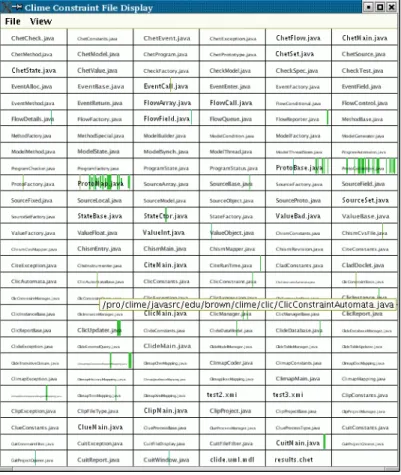
An alternative view of the constraints is shown in Figure 5.. This view lets the de-veloper see which files have potential problems at a glance. Moreover, the dede-veloper can click on a bar to get information on the particular constraint in the textual view or double click on a bar to bring up an appropriate editor.
8
Experience to Date
We have been using our constraint-based tool both on itself and for a small set of de-velopment projects, mainly to validate that the underlying systems work and that the ap-proach is a viable one.
The system is currently used in its own development (65,000 lines of Java plus about 250,000 lines of external Java libraries). Our experience has been that we did not Figure 4. Textual constraint presentation interface.
even notice when the automatic updates were occurring. While a full rebuild of the da-tabase takes around twenty minutes, incremental updates where fewer than 20 files have changed typically take one to two minutes. About a quarter of this time is spent updating the database by finding and analyzing changed files and then doing the incremental up-date. The remainder is spent updating the constraints where the bulk of the time in-volves evaluating the SQL queries associated with the metaconstraints, some of which are not as efficient as they should be using PostgreSQL, and most of which are evalu-ated due to table updates rather than item updates.
Our experience in using the system has shown it to be very helpful in identifying potential problems and inconsistencies. We have found and corrected numerous lan-guage and documentation problems in all the tested systems. For those systems where we have UML, we have been able to keep the UML synchronized with the source with-out having to completely regenerate it and hence lose the particular formatting and con-ventions we used in creating it initially.
9
Acknowledgements
This work was done with support from the National Science Foundation through grants CCF0218973, ACI9982266, CCR9988141. Manos Renieris and Shriram Krishnamur-thy provided significant advise and feedback.
10 References
1. Don Batory, David Brant, Michael Gibson, and Michael Nolen, “ExCIS: an integration of do-main-specific languages and feature-oriented programming,” in Workshops on New Visions
for Software Design and Productivity: Research and Applications, (dec 2001).
2. Bart Childs, “Literate programming, a practitioner’s view,” TUGboat, Proceedings of the
1991 annual meeting of the Tex User’s Group Vol. 12(3) pp. 1001-1008 (1991).
3. J. M. Cobleigh, L. A. Clarke, and L. J. Osterweil, “FLAVERS: A finite state verification tech-nique for software systems,” IBM Systems Journal Vol. 41(1) pp. 140-165 (2002).
4. Carolyn K. Duby, Scott Meyers, and Steven P. Reiss, “CCEL: a metalanguage for C++,” Proc.
Second Usenix C++ Conference, (August 1992).
5. Alexander Egyed, “Scalable consistency checking between diagrams -- the ViewIntegra ap-proach,” 16th IEEE Intl Conf on Automated Software Engineering, (November 2001). 6. David Evans, John Guttag, James Horning, and Yang Meng Tan, “LCLint: a tool for using
specifications to check code,” Software Engineering Notes Vol. 19(5) pp. 87-96 (December 1994).
7. Karl Fogel, Open Source Development with CVS, CoriolisOpen Press (1999).
8. Erich Gamma, Richard Helm, Ralph Johnson, and John Vlissides, Design Patterns, Addison-Wesley (1995).
9. E. Gamma and K. Beck, “Test infected: Programmers love writing tests,” http://
www.junit.org, (1998).
10. Clare Gryce, Anthony Finkelstein, and Christian Nentwich, “Lightweight checking for UML based software development,” 2002 Workshop on Consisteny Problems in UML-based
Soft-ware Development, (2002).
11. Donald E. Knuth, “Literate programming,” The Computer Journal Vol. 27(2) pp. 97-111 (1984).
12. Chris Laffra, Doug Lorch, Dave Streeter, Frank Tip, and John Field, “What is Jikes Bytecode Toolkit,” http://www.alphaworks.ibm.com/tech/jikesbt, (March 2000).
13. Christian Nentwich, Licia Capra, Wolfgang Emmerich, and Anthony Finkelstein, “xlinkit: A consistncy checking and smart link generation service,” ACM Transaction on Internet
Tech-nology, (To appear).
14. Steven P. Reiss, “Working with patterns and code,” Proc. HICSS-33, (January 2000). 15. Steven P. Reiss, “Constraining software evolution,” International Conference on Software
Management, pp. 162-171 (October 2002).
16. D. M. Ritchie, S. C. Johnson, M. E. Lesk, and B. W. Kernighan, “The C programming lan-guage,” Bell Systems Tech. J. Vol. 57(6) pp. 1991-2020 (1978).
17. Barbara G. Ryder and Frank Tip, “Change impact analysis for object-oriented programs,”
ACM SIGPLAN-SIGSOFT Workshop on Program Analysis for Software Tools and Engineer-ing, pp. 46-53 (June 2001).
18. Guy Lewis Steele, Jr., Common Lisp: the Language, Digital Press, Bedford, MA (1990). 19. Warren Teitelman, “A tour through Cedar,” IEEE Software Vol. 1(2) pp. 44-73 (April 1984).