Proceedings of the
Eighth International Workshop on
Graph Transformation and Visual Modeling Techniques
(GT-VMT 2009)
A Meta-Model-Based Approach for
Specification of Graphical Representations
Merete Skjelten Tveit
15 pages
Guest Editors: Artur Boronat, Reiko Heckel
Managing Editors: Tiziana Margaria, Julia Padberg, Gabriele Taentzer
A Meta-Model-Based Approach for
Specification of Graphical Representations
Merete Skjelten Tveit
Faculty of Engineering and Science, Department of ICT University of Agder, Grimstad, Norway
Abstract: Meta-models are widely used for the specification of the internal struc-ture of graphical modelling languages, and well-established standards (e.g. MOF) exist for this. For the graphical representation there is not the same agreement and no related standards. This paper presents a new meta-language for anindependent
specification of graphical representations. A diagram from the domain-specific lan-guage Service is used as a running example to show how this meta-model-based approach is appropriate for specifying the graphical representation in a precise way, but still on a high level of abstraction.
Keywords: language specification, graphical representations, meta-models, map-ping descriptions
1
Introduction
Graphical modelling languages are an important part of information technology and in the soft-ware development process as they are very suitable for visualising structures, compositions and relationships between elements. Unfortunately, there is not the same broad understanding and agreement of how these graphical languages are specified in a formal way. A formal language specification for a graphical language normally consists of a structure definition (also known as abstract syntax), a graphical representation definition (concrete syntax) and a definition of the semantics. A formal specification of the language, including the graphical representation is im-portant both for the users and for the tool developers that intend to build appropriate tool support for the language.
Meta-models are well-known as specification approach for thestructure of a language, and there already exist standards like MOF [OMG03] for this purpose. MOF is a meta-language, also called a meta-meta-model, and defines all the concepts that are necessary to specify the structure of a language. A language structure that is specified based on the concepts in MOF is said toconform toMOF. The UML 2.0 [OMG04] meta-model is an example of a language structure definition that conforms to MOF. The structure meta-model is in turn instantiated when models in the language are made. This kind of instance hierarchy is one of the fundamental concepts in a meta-model-based approach.
presents such a meta-language for specification ofgraphical representationbased on reuse and extensions of concepts from UML Infrastructure, with some extensions for the graphics. The meta-language defines all the concepts that are required to specify the graphical representation of languages. The placement of the approach in the hierarchy is illustrated at the right-hand side in Figure1. It is very important to note that the reuse of concepts from the UML Infrastructure does not restrict the application of meta-language to only the graphical representation of UML. This approach is suitable for most graphical languages, and is already applied to SDL [ITU99] in [PST07] and several domain-specific languages.
The main difference between the meta-language presented in this paper and already exist-ing model driven approaches for specification of graphical representation is the combination of
independence, completeness andexpressiveness. The independenceimplies that the graphical representation is specified independent of the structure meta-model. This independence is a clear advantage when the languages are complex and when it is necessary to have more than one graphical representation for the structure. This independence is also identified as a crucial part of language specification approaches in [Tve08a]. Because of this independence, it is important to have precisely defined mapping relations between the structure and the graphical representation. In addition to this, the meta-language gives the possibility to describe the graphical representa-tion of both languages and diagrams ascompleteconstructions. This is opposed to the UML-DI [OMG06], the closest to a standard for graphical representation, whose purpose is to exchange diagrammatic information, not specify it. Features to describe all kinds of spatial relationships between elements in a graphical language also make the meta-language moreexpressive than many other approaches. The approach that is most similar to ours regarding independence is GMF [GMF], but this approach has weaknesses both regarding completeness and expressive-ness. Section5presents these differences in more details.
The focus in this paper is mainly on the conceptual parts of the approach, nevertheless, a prototype that can be used to define graphical languages and generate graphical editors based on the description is implemented on the GMF platform, and is outlined in Section4. The following sections will give a bottom-up description of the approach, starting at the diagram level. Section 2 presents the meta-model-based approach both for a specific diagram and for the language aspects (Section2.3). Section2.4presents the most important concepts from the meta-language. Section3describes how the relationship between the structure and the representation is handled in this approach. The concluding remarks are found in Section6.
2
An Overview of the Approach
to specify the placementlogically. A logical placement is normally described by using spatial relationships to describe where an element is placed relative to other elements. A deeper outline on how graphical elements are spatially related and arranged in diagrams is found in [BG04]. In the approach presented in this paper, the arrangements of the graphical elements are also specified in a logical way usingspatial relationships.
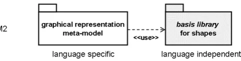
Figure 1: The meta-architecture of the approach
At the lowest level, M1, in the architecture presented in Figure1, we have thediagram descrip-tion model, which describes the graphical representation of one particulardiagram. This includes instances of the graphical elements, their properties and how they are related. The model is an
abstraction of a diagram, and iscompletein the sense that the diagram can be constructed from it. Thediagram description modelconforms to thegraphical representation meta-modelfor the language.
Thegraphical representation meta-modelspecifies all the graphical elements in the language, theirrolein the diagram and how they are spatially relatedto form well-formed diagrams. By role, we here refer to thetopological rolea graphical element plays, for instanceconnectionor
container. The approach provides a basis library which contains a set of pre-defined shapes. The library is language independent, that is, it can be used for all graphical representations. The graphical elements in the graphical representation meta-model specializes the pre-defined shapes in the library to get their geometrical properties. How the basis library is used in practise is described more detailed in Section2.3.
2.1 Specification of Graphical Representation
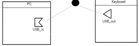
As an example for the article, a diagram from the domain specific languageServiceswill be used. The language is used to model service devices with plugs, and their connections. The example diagram in Figure2includes the following graphical elements: twodevice symbolswith names “PC” and “Keyboard”, onefemale plug symbolwith name “USB in” and onemale plug symbol
named “USB out”, oneconnection point symbol(the filled ellipse) and twoconnector symbols.
Figure 2: The service diagram used as running example
It is not only important to identify the graphical elements in a diagram, it is also necessary to describe how the elements could legally be related to each other. The relations between the elements are what actually create the diagrams in a language. For the service diagram we can recognise the following relations between the graphical elements: Thedevice symbolshave two
compartmentsplacedinside, onename compartmentand oneplug compartment. A horizontal line, also placedinsidethe device symbol, is separating the two compartments. Thedevice name
is placedinsidethename compartment. Theplug symbols are placedinsidetheplug compart-ments of the devices. The plug namesare associated withtheplug symbols. The connector symbolsareconnected toa plug symbolat their source end and to aconnection pointat their target end.
The next sections will give a bottom-up description of how the graphical elements and their spatial relationships can be specified in a meta-model-based way. We start with the description of thediagramin Section 2.2, the language graphical concepts in the servicelanguageare pre-sented in Section2.3and finally the most important concepts in the graphicalmeta-languageare presented in Section2.4.
2.2 The Diagram Description Model (M1)
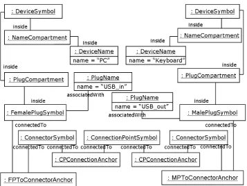
The graphical elements and how and where they are related form the most important aspects of the graphical representation of the service diagram, and are also what we would like to describe in the diagram description modelin Figure 3. This diagram model is an object model which conforms to a meta-model defining the meta-classes like DeviceSymbol and ConnectorSymbol. The graphical elements are represented as objects and the relations as plain links with end names representing the spatial relationships between the elements involved in the relation. The meta-model is presented in Section2.3.
rela-Figure 3: The diagram description model (M1) specifying a complete abstraction of the service diagram
tionships are also presented in the model: inside,connectedToandassociatedWith. Theinside
relation represents one graphical element placed inside another graphical element, and is given in the model as a link between the two objects that are involved in the relationship, e.g. thedevice name“PC” inside thename compartment.
The associatedWith relationship describes a special kind of relation since it is not directly visible in the diagram. An example of use is the instance of aplug name which is associated with an instance of amale plug symbolorfemale plug symbol. In the diagram it is not possible to see that these elements have a concrete relationship in between, but they are still related with an ”invisible” association.
The connectedTo relationship is used to describe that two (or more) graphical elements are connected physically to each other. In the service diagram we have theconnector symbolwhich at each target end is connected to the border of a connection point symbol. The connectedTo relationship (and also the associatedWith in some cases) also involves ananchorobject (e.g. cp connection anchor) that specifies where the connecting appears. The anchor specifies a single point or a set of points that represent the concrete intersection point/area between the graphical elements that are involved. In the diagram description model (Figure 3), the cp connection anchorsspecify one single point at the border of the connection point where it intersects with thetarget endof aconnector symbol.
relationships, and also more specific connection areas, than for the connectors and connection points.
2.3 The Graphical Representation Meta-model (M2)
The model in Figure3is an abstraction of how the elements are arranged in the particular di-agram. The objects in the model are instances of the graphical elements which are specified for thelanguage. One particular diagram is justone, among many, legal representations in a language. At the M2 level in the meta-model hierarchy (see Figure1) we have the graphical representation meta-modeldescribing all the graphical elements in the language and their legal, spatial relations.
Figure 4: The graphical representation meta-model uses a language independent basis library
Thegraphical representation meta-modelconsists of an identification of all the graphical el-ements in the language, which roles (connection,container shapeetc.) they play and how they are related to form well-formed diagrams. The graphical elements get their geometric properties from classes in a basis library (see Figure4). The language independentbasis librarycontains a number of pre-defined shapes that are considered as the most important shapes for graphical languages. The abstract descriptions of the geometrical shapes are all instances of UML::Class (cf. Section 2.4). The relationship between the graphical representation package and the ba-sis library package is expressed by the UML dependencyuse, and the relationship between the graphical elements and the related pre-defined shapes is expressed byinheritance(also UML) in the meta-model for graphical representation. This implies that the graphical elements get the semantics of their roles from the meta-language at the M3 level, and their geometrical shape by inheritance.
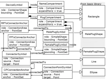
Figure 5: A subset of thegraphical representation meta-model(M2) for the Service language
Theconnector symbol is shaped like alineand plays the role as aconnection. A connection is special since it is always a part of aconnectedTorelationship. For all the shapes in the basis library that are not characterised by their circumference, for instance different variations of lines, the attachment areas are set based on the endpoints of the shape. Aconnector symbolis shaped like alineand are in the basis library provided with two properties,sourceandtarget.
The anchor property in the connection area is derived from the attachment properties for the graphical elements involved in the relationship, and represents the possible intersection point/area. For the cp connection anchor, the anchor is specified (by constraint) to be all the possible points where thetarget of theconnection symbolintersects theattachment areaof the
connection point. On this level, the anchor is relative to the involved elements. Thecompartment
role is used for specification of compartments within acontainer shape.Name compartmentand
plug compartmentare examples, and they both expandthe container, the device symbol, hori-zontally.
many cases, which makes it difficult to specify attachment areas that are unequal to the shape boundings. The meta-model-based approaches that are most similar to the one presented in this paper, are described in more detail in Section5.
2.4 The Graphical Meta-meta-model (M3)
Thegraphical meta-meta-modelis the meta-language at the M3 level in the meta-model hierar-chy (see Figure1), and defines all the concepts that are necessary for specification of graphical representations. This section presents a slightly simplified version of the meta-meta-model, with focus on the concepts that are used in earlier sections.
Figure 6: The meta-language (M3) for graphical representations
As a meta-language it is defined at the same level as MOF, and as for MOF it is defined by a meta-meta-model by re-using concepts from UML Infrastructure. The meta-classes representing
rolesare all defined as subclasses of UML::DataType which gives the type to theroleproperty as illustrated in Figure 6. The role a graphical element plays, impacts which kind of spatial relationship the element can be a part of. There are four main kinds of types which all represent a specialrole a graphical element can have: shape, connection, connection area andtext. A
container shapeis a special kind of shape that acts as container for other graphical elements. A container shape can containcompartments, which are used to arrange their contents.
Also here, concepts from UML Infrastructure are used as basis. The most important concept is thespatial property, which is an extension of UMLproperty. This concept gives the possibility to expressspatial relationships(extension of UML association) with aggregation, multiplicity and navigable end. The new feature presented in spatial property is thespatial kind. This property is used to specify which kind of spatial relationship (inside,connectedTo,associatedWith) that exist between graphical elements.
The properties for the different roles on the language level are semantically generated from OCL constraints that are defined for the meta-language. For instance, onlycontainer shapes
can act as containers for other graphical elements. This implies that whenever aninsiderelation is specified in the meta-model for graphical syntax, we need to assure that the element at the opposite end of the inside property, is of typecontainer shape.
context SpatialProperty
inv: self.kind = SpatialKind::inside implies spatialRelationship.memberEnd ->
forAll( s | s <> self implies
s.class.ownedRoleProperty.datatype -> oclIsKindOf(ContainerShape))
As we can see, the meta-language for specification of graphical representation is not very different from MOF, but it contains some additional semantics which are especially related to the different roles that a graphical element can have and the spatial arrangement of graphical elements.
3
Relating the Representation and the Structure
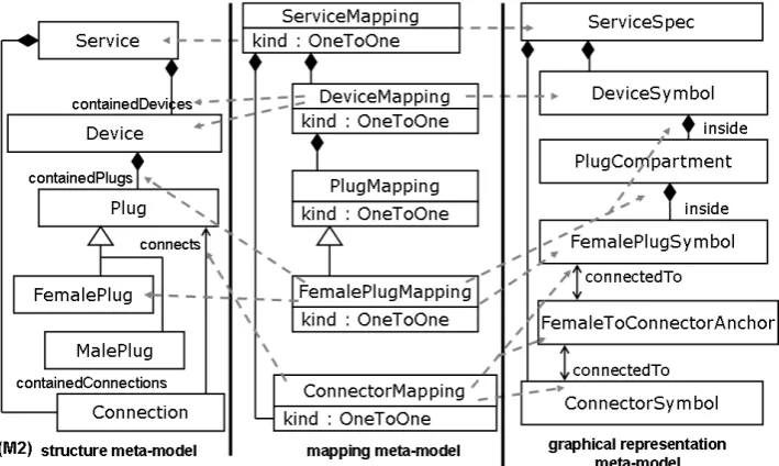
As we have seen in Section 2, the graphical representation is specified completely indepen-dent from the structure definition. This means there needs to be some kind of mapping defined between the two syntactic aspects to keep them synchronized. The complete separation is an important feature in this approach as it gives the possibility to have several representation def-initions for the same structure and vice versa. The importance of keeping the structure and representation separated is discussed more widely in [Fon07]. The mapping meta-language that is defined within this approach is based on a study of the graphical languages SDL [ITU99] and UML [OMG04] and a categorisation of their relationships between the structure and the representation. From this study, three important mapping patterns were identified.
• One-to-oneis the simplest kind of mapping, and also the most common.
• Merge is used to map graphical concepts which have several notation options. A well known example is signal declarations in SDL.
• Partial descriptionis used to map graphical concepts which have a partial representation in addition to a complete. A typical example is partial descriptions of classes.
transformed to the gmfmap model in the GMF framework. This is expressed in Figure9in Sec-tion4. In the Service language, all mapping relationships are described using instances of the
Figure 7: Illustration of mapping relationships in the Service Language
one-to-onepattern. This is illustrated in figure7.
4
The Architecture of the Implementation
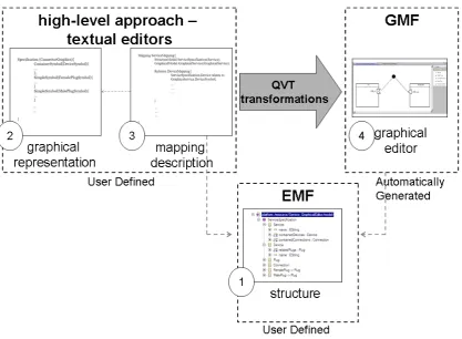
The prototype is implemented using the Eclipse framework, EMF, GMF and QVT for model-to-model transformation. The aim of the tool is to be able to use the approaches for specification of the graphical representation and the mapping description to generate a graphical editor. Figure8 gives an overview of the workflow in the prototype.
To generate a graphical editor for a language using the prototype, the user needs to define:
1. Thestructureof a language.
2. Thegraphical representationof a language
3. Themapping descriptionthat specifies the relationships between the graphical representa-tion and the structure.
These three definitions, which together cover the complete syntactic aspects of a language, is automatically transformed using pre-defined QVT transformation, to GMF descriptions of the given language. The descriptions provide the necessary information to automatically generate:
Figure 8: An overview of the implementation
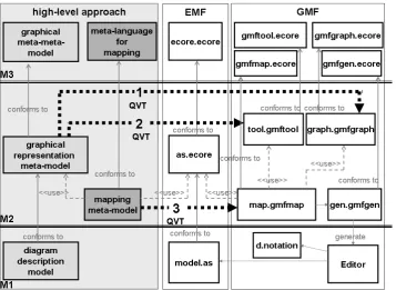
The Eclipse Modeling Framework (EMF) [BSM+03] makes it possible to easily create tree-editors by generating code from the meta-languages for graphical representation and mapping that are defined as ecore-models. These tree-editors can be used directly to specify the graphi-cal representation, and the mapping relationships to the structure. To make the prototype more user-friendly, the Textual Editing Framework (TEF) TEF [Sch08] have been used to specify textual representations and to generate textual editors for the two meta-languages. The textual editors makes it more straight-forward to specify a graphical language and its representation. Thishigh-leveldescription is thentransformedto the lower level GMF framework [GMF] which is responsible for generating the graphical editor features that are necessary. The model-to-model transformations between the high-level specification and the GMF model-to-models are completely handled using QVT-R [OMG08], implemented using the toolikv++ medini QVT. The transfor-mations are illustrated in Figure9 which shows the high-level approach on the left-hand side, the GMF framework on the right hand side (with the EMF in the middle since the structure meta-model is used by both approaches) and the transformation arrows in between. The three transformation descriptions are in the figure illustrated by numbered, stippled arrows:
1. from the graphical representation meta-model to graph.gmfgraph
Figure 9: An overview of the high level approach (left-hand side) and its transformation to the GMF platform
3. from the mapping meta-model (high-level approach) to map.gmfmap
These three gmf-models are sufficient for generating a GMF editor.
There are some minor differences between the conceptual aspects presented in Section2and the practical aspects covered by the prototype. This is mostly related to the implementation of the meta-language, since the conceptual part of the approach are described re-using concepts from UML Infrastructure, while the implementation is based on EMF. These differences are solved as follows: TheUML::Classis replaced byEClass. For thespatial relationship, which extends UML::Association, andspatial property, which extends UML::Property, the challenge is bigger. While UML uses associations, with properties for the association ends, EMF uses references to express relationships between classes. In the implementation, this is solved by merging the
spatial relationshipandspatial propertyinto one unit, and let it extendEReference. The property
EOppositefromEReferenceis used on the level below to express bidirectional spatial relations between graphical elements. By adding theproperty kindof typespatial kindto the new unit all the necessary semantics are kept.
5
Related Work
Framework (GMF) [GMF], MetaEdit+ [Met05], The Generic Modeling Environment (GME) [LBM07] and Tiger [EEHT05] to mention some. All of these meta-tools present their own ap-proach for handling and specifying the graphical representation. While most of these apap-proaches (e.g. MetaEdit+ and GME) specifies the graphical representation on top of the structure meta-model and with this keep the graphical information as properties in the structure elements, GMF and XMF-Mosaic presents new, independent meta-languages for the graphical representation. The graphical representation description is then related to the structure meta-model by a syntac-tic mapping description. Of these two, GMF is the approach that shares most with the approach presented in this paper as it has a strong focus on separating the structure and the representation. The biggest differences between the Eclipse-based GMF and the approach presented in this paper are related to two aspects:expressivenessandcompleteness. It is not possible to explicitly specify spatial relationships between graphical elements or specific attachment areas in GMF, except compartments, which make it possible to handle inside relationships. The relationships between nodes and connections are handled implicitly. This implicit specification makes the approach less expressive than the one presented in this paper. The other difference is related to the completeness of the graphical representation. The meta-language presented in this approach aims to specify the graphical representation as a complete construction (model), and not only single graphical elements collected in a container (canvas in GMF) without any relationships in between. In GMF, the relationships between a compartment and its content, and between a connection and its connected node, are specified in the mapping description, and not in the graphical representation itself.
This is also the case for another approach presented by F. Fondement in [Fon07] that is worth mentioning. This approach is different from both GMF and XMF as it does not provide a new meta-language for the graphical representation, but instead proposes to extend the already exist-ing structure meta-model by an extra layer of visual objects. This approach is interestexist-ing as it presents features for specification of spatial relationship (contains, overlap, connects and nearby) between graphical elements. The weakness with this approach, as with GMF, is that the spatial information is specified as a part of the mapping description, and not in the graphical represen-tation itself.
6
Conclusion
A prototype tool for the meta-languages for graphical representation and the mapping ap-proach are implemented, based on EMF and transformed to the GMF platform. In the tool the meta-languages has textual representations and textual editors implemented using TEF [Sch08]. With this, the approach can be used to specify the graphical representation of a graphical lan-guage, which together with a structure specification and the mapping description makes it possi-ble to generate a GMF editor from the specification. The future plan is to also specify a graphical representation for the meta-language and generate a graphical editor for it, using the approach and the meta-language itself.
Bibliography
[BG04] P. Bottoni, A. Grau. A Suite of Metamodels as a Basis for a Classification of Vi-sual Languages.2004 IEEE Symposium on Visual Languages and Human-Centric Computing (VL/HCC 2004), 26-29 September 2004, Rome, Italy, pp. 83–90, 2004.
[BSM+03] F. Budinsky, D. Steinberg, E. Merks, R. Ellersick, T. J. Grose. Eclipse Modeling Framework (The Eclipse Series). Addison-Wesley Professional, Aug. 2003.
[EEHT05] K. Ehrig, C. Ermel, S. H¨ansgen, G. Taentzer. Generation of visual editors as eclipse plug-ins. In20th IEEE/ACM International Conference on Automated Software En-gineering (ASE 2005), November 7-11, 2005, Long Beach, CA, USA. Pp. 134–143. 2005.
[Fon07] F. Fondement. Concrete Syntax Definition For Modeling Languages. PhD Thesis. Ecole Polytechnique Federale De Lausanne, 2007.
http://library.epfl.ch/en/theses/?nr=3927
[GMF] Graphical Modeling Framework. http://www.eclipse.org/gmf
[ITU99] ITU-T. SDL - ITU-T Specification and Description Language (SDL-2000). ITU-T Recommendation Z.100, 1999.
[LBM07] A. Ledeczi, D. Balasubramanian, Z. Moln´ar. An Introduction to the Generic Model-ing Environment. InProceedings of MDD-TIF07, Model-Driven Development Tool Implementers Forum. 2007.
http://www.dsmforum.org/events/MDD-TIF07/GME.2.pdf
[Lim05] X. Limited. Language Driven Development and XMF-Mosaic. 2005. http://www.xactium.com
[Met05] MetaCase. MetaEdit+. Version 4.0. Evaluation Tutorial. Technical report, MetaCase, 2005.
http://www.metacase.com/support/40/manuals/eval40sr2a4.pdf
[OMG03] OMG. Meta Object Facility (MOF) 2.0 Core Specification. Object Management Group, Oct. 2003. ptc/03-10-04.
[OMG04] OMG. UML 2.0 Superstructure Specification. Object Management Group, Oct. 2004. ptc/04-10-02.
[OMG06] OMG. Diagram Interchange, version 1.0. Object Management Group, Apr. 2006. ptc/06-04-04.
[OMG07] OMG.OMG Unified Modeling Language (OMG UML) Infrastructure, V2.1.2. Ob-ject Management Group, Nov. 2007. ptc/06-10-06.
[OMG08] OMG. Meta Object Facility (MOF) 2.0 Query/View/Transformation Specification. Object Management Group, Apr. 2008. ptc/07-07-08.
[PST07] A. Prinz, M. Scheidgen, M. S. Tveit. A Model-Based Standard for SDL. InSDL Forum. Pp. 1–18. 2007.
[Sch08] M. Scheidgen. Textual Modelling Embedded into Graphical Modelling. In Model Driven Architecture - Foundations and Applications, 4th European Conference, ECMDA-FA 2008, Berlin, Germany, June 9-13, 2008. Proceedings. Lecture Notes in Computer Science 5095, pp. 153–168. Springer, 2008.
[Tve08a] M. S. Tveit. Specification of Graphical Representations - using hypergraphs or meta-models? In Norsk informatikkonferanse NIK 2008. Pp. 39–50. tapir akademiske forlag, 2008.