O R I G I N A L R E S E A R C H
Open Access
A review of cyber security risks of power
systems: from static to dynamic false data
attacks
Yan Xu
Abstract
With the rapid development of the smart grid and increasingly integrated communication networks, power grids are facing serious cyber-security problems. This paper reviews existing studies on the impact of false data injection attacks on power systems from three aspects. First, false data injection can adversely affect economic dispatch by increasing the operational cost of the power system or causing sequential overloads and even outages. Second, attackers can inject false data to the power system state estimator, and this will prevent the operators from obtaining the true operating conditions of the system. Third, false data injection attacks can degrade the distributed control of distributed generators or microgrids inducing a power imbalance between supply and demand. This paper fully covers the potential vulnerabilities of power systems to cyber-attacks to help system operators understand the system vulnerability and take effective countermeasures.
Keywords:False data injection, Economic dispatch, Power system state estimation, Distributed control, Microgrid
1 Introduction
With their extensive incorporation of information and communication technology, power systems are exposed to cyber threats. By targeting the information exchange process, malicious attackers can inject false data to cause power outage, economic loss, and system instability. False data injection (FDI) can also be employed to mask existing power system faults. This will affect operator’s visibility on the faults and prevent proper countermea-sures from being taken.
For example, in 2015, the Ukraine power grid was attacked and substation breakers were opened by mali-cious entities [1]. To design proper protection measures for the improvement of system resilience, it is necessary to explore the way FDI affects the power system. Thus, there has been a lot of research on the attacking mech-anism and effect of FDI.
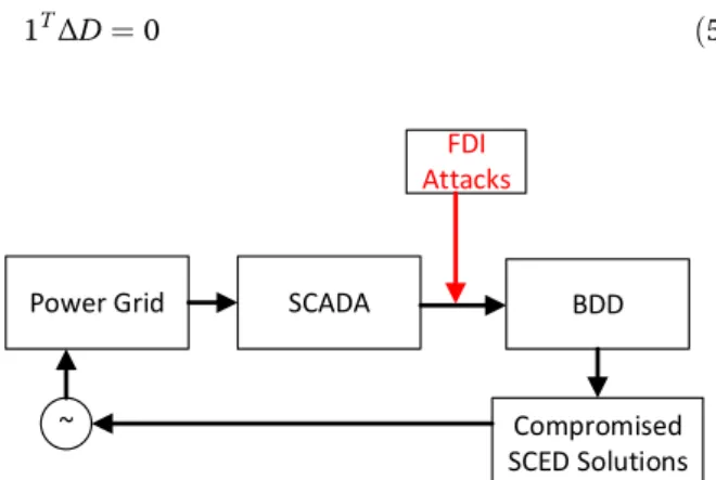
In general, the paths through which FDI adversely affects a power system can be classified into three
categories, i.e., the estimation of system states, the generation of control commands, and the actuation of control actions, as shown in Fig. 1. FDI can induce the generation of inappropriate control commands by directly targeting economic dispatch. In [2,3], false load data is injected into security-constrained economic dispatch which causes the line flows to exceed their overload tripping threshold, leading to line outage and even cascade failure. In [4–6], economic dispatch is intentionally affected to increase the operational cost or to obtain illegal profit from power markets. In [7], the potential risk of FDI attacks on economic dispatch is investigated where the attackers do not have full know-ledge of network information. FDI can also penetrate a power system by attacking system state measurement and estimation, and cause damage to the integrity of power system state information. In [8], FDI is used as a tool to attack the supervisory control and data acquisi-tion (SCADA) system, while in [9], false data is injected into the phasor measurement unit (PMU) to mislead the control center. By doing this, cyber attackers can affect
© The Author(s). 2020Open AccessThis article is licensed under a Creative Commons Attribution 4.0 International License, which permits use, sharing, adaptation, distribution and reproduction in any medium or format, as long as you give appropriate credit to the original author(s) and the source, provide a link to the Creative Commons licence, and indicate if changes were made. The images or other third party material in this article are included in the article's Creative Commons licence, unless indicated otherwise in a credit line to the material. If material is not included in the article's Creative Commons licence and your intended use is not permitted by statutory regulation or exceeds the permitted use, you will need to obtain permission directly from the copyright holder. To view a copy of this licence, visithttp://creativecommons.org/licenses/by/4.0/.
Correspondence:[email protected]
the operator’s visibility on the true operating condition of the system, resulting in the failure of the operator to take appropriate countermeasures. In [10, 11], FDI is employed to induce arbitrary estimation errors of the state estimator, whereas FDI is applied to power system nonlinear state estimation in [12–15] and the corre-sponding countermeasures are discussed. In addition, FDI can modify the control input for the system, result-ing in deterioratresult-ing power system stability. In [16], the input signal for a follower distributed generator is cor-rupted by FDI, causing the disagreement of a group of distributed generators. In [17], FDI is used to induce a synchronization problem for islanded microgrids, while system breakers are controlled to trigger instability in [18], and the gains of voltage control devices altered to initiate transient instability in [19]. In [20], a malicious attack is implemented through emulated inertia control to cause instability of system frequency.
At present, investigation into the impact of FDI is mainly based on the single-snapshot FDI model and/ or the steady-state power system model, while the re-search considering the transient process of a power system is not thorough and comprehensive. To avoid being detected or reduce energy consumption during the attack process, smart attackers may change the injected data at every attack time instant. The use of the steady-state power system model is also not adequate to analyze the risk of FDI, as real power systems are networked control systems. Even though system state estimation and economic dispatch are resilient to FDI, attackers can still disrupt power system secure operation by attacking the automatic generation control system. Accordingly, considering FDI’s dynamic characteristic and power system transi-ent characteristic is of paramount importance to fully reveal the risk of FDI and then design effective countermeasures.
To unveil the risk of FDI in a comprehensive fashion, this paper reviews the research on FDI attacks on economic dispatch, state estimation, and power system dynamic stability, as shown in Fig.1.
2 Attacks on economic dispatch
2.1 Overloads caused by FDI attack
In a real power system, generators are dispatched every 5–15 min to minimize the operational cost. The load data adopted for security-constrained economic dispatch (SCED) is from the short-term load forecast, which uses historical and/or real-time load measuring values as in-put. False data which can pass the bad data detection (BDD) can be deliberately injected to alter the load in-formation for the SCED and to modify the enforcement of branch flow limits, as shown in Fig.2.
Let ΔD denote the injected data. The limits for line flows imposed by the SCED can be represented by [4,5]:
PFDI ¼SF KPP0−KDðDþΔDÞ
ð1Þ
−r≤PFDI≤r ð2Þ
wherePFDI is the branch flow vector andDis the actual
bus load vector. KP and KD are the bus-generator and
bus-load incidence matrices, respectively. SF is the
gen-eration shift factor matrix and ris the normal capacity rating of the lines.
In addition, the true load used in the SCED is denoted byDand the true branch flow is given as:
P¼SF KPP0−KDD
¼PFDIþSFKDΔD ð3Þ
Combining (1) and (3) shows that the true branch flow Psatisfies the constraint as:
−rþSFKDΔD≤P≤rþSFKDΔD ð4Þ
Equation (4) reveals that the true line flow is greater than its limits, i.e., |P|≥r. In real-time operation, if a generator follows the dispatch commands generated by the SCED under a FDI attack, severe transmission overloads may be induced, causing triggering actions of protection devices.
To launch a practical FDI attack, the injected dataΔD needs to satisfy the following constraints [6,7]:
1TΔD¼0 ð5Þ Fig. 1Cyber-attacks on a power system
−τD≤ΔD≤τD ð6Þ Equation (5) means that the sum of load changes is zero to guarantee power balance, while (6) constrains the magnitude of the FDI attack at a load bus. Such con-straints for a FDI attack are commonly employed in the existing literature.
The above FDI attack model reveals the potential risks for safe power system operation, as blackouts in a power grid are usually caused by overloads and outages [21, 22]. As described in [23], three successive transmission line and transformer tripping were the main causes of the 2003 Northeast Blackout and the 2011 Southwest Blackout, respectively. Once an ensemble of critical lines known as initial contingency (IC) is identified [24, 25], attackers can deliberately induce this initial contingency by using an FDI attack. Given the capability of the IC, sequential outrages and even cascade failures can be initiated, as illustrated in Fig.3.
2.2 Increase of operational cost caused by FDI attack
Attackers can increase the operational cost of a power system by interrupting the SCED and changing the transmitted load data. The attack vector can be optimized by maximizing the operational cost, which is formulated as a bi-level linear programming problem as:
c¼ max
ΔD c T gPþc
T
dJ ð7Þ
Subject to 5ð Þand 6ð Þ ð8Þ
min P;J c
T
gPþcTdJ ð9Þ
Subject to 1TP¼1TðD−JÞ ð10Þ
F¼SFKPP−SFKDðDþΔD−JÞ ð11Þ
Pmin≤P≤Pmax ð12Þ
−fmax≤F≤fmax ð13Þ
0≤J≤DþΔD ð14Þ
where cgand cd are the generation cost and load
shed-ding cost vector, respectively. F is the calculated line flow vector containing false data, fmaxis the branch flow
limit vector, and J is the load shedding vector. P is the generator output power vector, and Pmin and Pmax are
the lower and upper bounds for the generator output, respectively.
The upper level (7)–(8) shows that the false dataΔDis obtained by maximizing the load shedding after SCED. In the lower level (9)–(14), the operational cost is minimized with the corrupted load data D+ΔD by considering the generator output power limits (12), transmission line flow limits (13), and load shedding limits (14).
Karush-Kuhn-Tucker (KKT) and dual based methods are widely used to solve the abovementioned bi-level optimization problem [4, 26]. The KKT-based approach requires the introduction of additional binary variables to form the so-called big-M constraints, reducing the computing efficiency of the algorithm. As regards the duality-based method, the bilinear terms of dual variables and the corresponding primal variables are involved, and thus the optimization problem is not easy to solve.
An alternative for attackers to construct the attack vector by using a fast approach is presented in [5]. In order to increase the operational cost, the loading levels of the branches in set Ω are maximized through false data injection. The resultant optimization problem to determine the false dataΔDis described by:
max
ΔD
X
l∈Ω
δl −
SlKDΔD
fmaxl ð15Þ
Subject to constraints 5ð Þ- 6ð Þ ð16Þ
where l denotes the transmission line and Sl is the l-th
row ofSF.
The objective function is to maximize the loading levels of the transmission lines in setΩ.δl= 1 if the flow
of line l is positive, and δl=− 1 otherwise. The term−
SlKDΔD denotes the incremental power flow through
linelcaused by the injected false dataΔD.
The false data ΔD can be obtained by solving (15), based on which the optimizing operational cost problem (9) with constraints (10)–(14) can be easily solved. Since the attack vector is determined by solving the linear programming problem (15), the run time is significantly reduced compared to the KKT-based approaches.
of the vulnerability of communication technologies. For example, a malicious agent may inject false data to in-duce the operators to make the wrong decision on the system status.
3.1 FDI attack with complete network information
Measurements are used to estimate the system state and because of the existence of measurement errors, opera-tors predefine a threshold to detect bad data. If the threshold is exceeded, the measurements are considered to be bad data. Hence, if attackers want to launch a successful attack by FDI, the injected false data has to pass the bad data detection. Power system state estima-tion can be expressed as [11]:
^x¼ arg minkz−Hxk2 ð17Þ
where x is the state vector and ^x is the estimated state vector. z is the measurement state, H the Jacobian matrix of the power system, and ‖⋅‖2 the Euclidean norm.
To detect the bad data, the residueris defined as:
r¼kz−Hxk2 ð18Þ
The term on the right-hand side of (18) indicates the difference between the measured and actual values. This difference is caused by measurement errors and disrup-tions. A threshold for r is pre-determined by the operator, and data is considered to be bad if the thresh-old is exceeded.
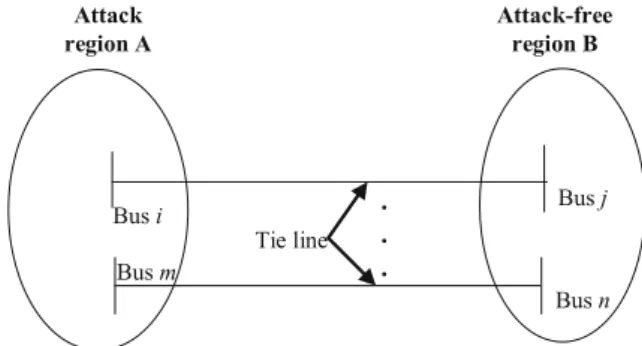
For illustration purposes, a power grid is divided into regions A and N with a set of tie lines between them, while the measurements in region A are assumed to have been attacked by a malicious entity. The measure-ment vector z is decomposed into z1 and z2, where z1 contains all the measurements in the targeted region A without the power flow measurements on the tie lines andz2collects the rest of the measurements in regionA. Similarly, the state vector x is divided into x1 and x2, where x1collects all the buses in the targeted region A without the boundary buses and x2contains the rest of the buses.
To attack the measurements in region A, attackers need to design an attack vector to pass the bad data detection in state estimation. This means that the false data injected by the attackers should prevent the residual of the state estimation from exceeding its threshold.
In the absence of the injected false data, the ment errors contribute to the residual. If the measure-ments are noise-free, the residual is equal or close to zero. In reality, measurement inaccuracy causes incon-sistent measurements, leading to an increase of the re-sidual. Less consistency of measurement implies a higher
residual. Smart attackers may construct false data that are consistent with the physical property of the power system. Therefore, the false data z01 designed by the at-tackers is likely to follow Kirchhoff’s Current Law (KCL) and Kirchhoff’s Voltage Law (KVL), given by:
z01¼H11x1þH12^x2 ð19Þ
The measurements in the attack-free region are unchanged.
The attacking mechanisms of FDI on power system state estimation have been elucidated in [8–10, 12–15]. When the false data is not injected, the state estimation equation is given by:
z1 z2 ¼
H11 H12
0 H22
^
x1
^
x2 þ e1
e2 ð20Þ
wheree1ande2are the measurement errors ofz1andz2, respectively. It can be seen that z2is only a function of
x2. In the case of DC state estimation,H11,H12, andH22 are constant, while they are functions of the state vector in AC state estimation.
When the false data is injected, measurementz1is re-placed by the attack vector z01, and the corresponding
measurement vector is denoted as z0 ¼ ½z01z2
T
. Then the residual is represented by:
r0¼ minz0−Hx02 ð21Þ
To obtain a feasible estimate of the state vector xb0
¼ ½x1^x2T , the following constraint needs to be satisfied:
r0≤z0−Hxb0 2¼
z0−ðH11x1þH12^x2Þ z2−H22^x2
2
¼ 0
e2
2
¼k ke2 2<r¼ e1 e2
2
ð22Þ
Equation (22) reflects the decrease of the overall re-sidual as the false data is injected. This can be explained by the fact that the false data injected in the attack re-gion obey KCL and KVL, and hence have better consistency than the original measurements. It should be clarified that the decreased residual under FDI attack does not necessarily imply that the false data is close to the true value [11]. In fact, attackers can simultaneously induce severe disruptions while maintaining a small re-sidual by FDI.
pij¼V2igij−ViVj gij cos θi−θj
þbijsin θi−θj
ð23Þ
qij¼ −V2ibij−ViVj gij sin θi−θj
−bij cos θi−θj
ð24Þ
whereViis the voltage magnitude at bus i.bijandgijare
the susceptance and conductance between line i-j, re-spectively. pij and qij are the active and reactive power
flows between linei-j.
Since KCL is applicable in (19) for the non-boundary buses in the attack region, the algebraic sum of the flows of the lines connected to a bus equals the power injected at this bus. For the boundary buses in the attack region, parts of the lines linked to this bus belong to the non-attack region (see Fig. 4). Hence, the resulting power balance equations are expressed as:
piþ
X
j∈Si;A
pijþ
X
j∈Si;N ^
pij¼0 ð25Þ
qiþ X
j∈Si;A
qijþ X
j∈Si;N ^
qij¼0 ð26Þ
^
pij¼V^2igij−V^iV^j gij cos ^θi−θ^j
þbij sin ^θi−^θj
ð27Þ
^
qij¼ −V^2ibij−V^iV^j gij sin ^θi−^θj
−bij cos ^θi−θ^j
ð28Þ
where pi and qi are the active and reactive power
injected into busi. pijand qijare the active and reactive
power flows of linei-jout from the attack region.
From (27) and (28), we see that the measurements in the non-attack region are not attacked. Thus,^pij and ^qij in (25) and (26) are of the given values, which will change the Jacobian matrix of the power injected into the boundary buses.
Note that (17) results in the state variables on one snapshot. To account for the dynamic behavior of FDI, (17) can be easily reformulated as a summation ofz−Hx over T snapshots, and the resulting optimization prob-lem can be solved in a similar way. The details can be found in [27].
3.2 FDI attack with incomplete network information
Equation (19) indicates that the constructed attack vec-tor z01 depends on the estimates of voltage magnitudes and phase angles of the boundary buses in the attack re-gion. It also requires the attackers to have the topology information of the whole power network as well as line parameters [8–10, 12–15]. However, network informa-tion of a power grid is confidential and the attackers are likely to have difficulty in obtaining this. In addition, there exist thousands of buses and lines in a modern power system. This means that the attackers need to deal with extensive information concerning network top-ology. Therefore, the assumption that attackers are able to acquire the estimated values from state estimation is impractical.
To construct a practical attack model against state es-timation, the above conditions are relaxed in [11], in which the false data injection model requires only the network information of the attack region (see Fig.5) ra-ther than that of the whole power network. In addition, the attack vector in [11] does not directly rely on the es-timates of phase angles but rather the angle differences of the lines. The FDI attack model used in [11] is refor-mulated by the following steps:
1) Substitute the measured voltages for the estimates of voltage magnitudes at the boundary buses in the attack region;
2) Replace the estimates of voltage magnitudes and phase angles with the corresponding measurements to determine the flows on the tie lines.
Fig. 4A boundary bus in the attacking region
By doing the above, the estimated state of the system is no longer required in the design of the attack vector.
The phase angles at the boundary buses in the attack region play an essential role in the implemen-tation of the mentioned attack model. Even though the measurements of phase angles can be accessed by PMU, this would require the deployment of sufficient PMUs to provide this information, and such solutions can be hard to scale up. To successfully launch an FDI attack on a power system without sufficient PMU data, it is desirable for attackers to construct a more practical attack model without requiring the measured values of the phase angles. From the perspective of the defender, it is also of paramount importance to explore the possibility of attacking state estimation using such an attack model.
According to (23) and (24), line flow in a power system is computed using the angle difference of the line. If the angle differences between lines are known, the line flows can be determined. This means that the actual phase angles at the boundary buses are not required to determine the line flows, and the angle differences of the line can be used to compute the attack vector in (19) even in the absence of actual bus phase angles. The following investigates how to employ line angle differences instead of bus phase angles to design the attack vector.
Equation (19) implies that phase angles at the bound-ary buses are fixed to the estimates of the state estima-tor. Accordingly, the angle differences between buses are also fixed. Considering the actually estimated phase angle at busito be^θi, the following expression holds:
^
θi−θ^j¼ θ^iþα
− ^θjþα
ð29Þ
Equation (29) shows that when the phase angles of two boundary buses are changed by α, the correspond-ing angle difference is unchanged. Thus, the phase angles used for the calculation of the attack vector can be obtained by the following steps [11]:
Step 1. Select an arbitrary value for a boundary bus; Step 2. Choose the phase angles for the remaining boundary buses based on the angle differences.
Due to the random value for the boundary bus, the phase angles obtained by the steps above do not repre-sent the actual ones. However, the angle differences are the same as the actual ones, and thus the line flows are unchanged. Therefore, there is no need for attackers to acquire the actual values of the estimated phase angles to construct the attack vector, and the only information needed is the differences of the estimated phase angles.
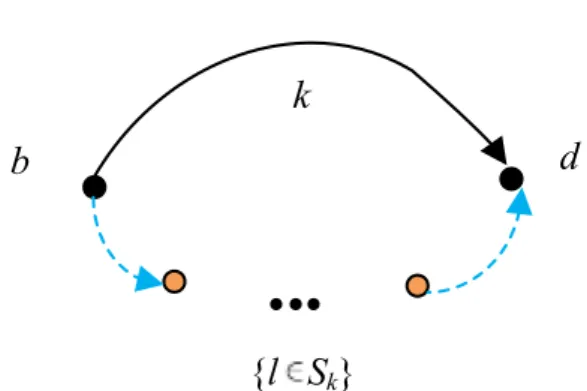
Assuming there is a pathkthat links two neighboring buses, as shown in Fig.6, it can be proved that the fol-lowing equation holds for a specified direction:
X
l∈Sk
δl¼θb−θd ð30Þ
From (30), for the path {l∈Sk} connecting busbandd,
the angle difference between the two buses can be com-puted by summing the angle differences of lines in this path. This means that attackers do not need to acquire the actual values of estimated phase angles at the bound-ary buses. To compute the angle difference without knowledge of the actual phase angles, the following ap-proximations are considered:
cos θi−θj
≈1; sin θi−θj
≈θi−θj;Vi≈Vj≈1 ð31Þ
Substituting (31) into (27) yields
pij≈ θi−θj xij
ð32Þ
Thus, the angle difference can be computed as:
θi−θj≈xijpij ð33Þ
Equation (33) shows that the line power measurement can be employed to compute the angle difference, while the error of the angle difference is partly caused by the use of the approximations in (31). Therefore, the accur-acy of the angle difference obtained by (33) depends on the conditions under which (31) holds. It is known that the difference reduces with the increase of the X/R ratio of a line. Thus, to reduce the error induced by (31), an optimal pathkin the attack region is identified by maxi-mizing the average X/R ratio ofρkas [11]:
ρk¼ 1
nk
X
l∈Sk
Xl
Rl
ð34Þ
As shown in (22), to avoid being detected by the bad data detection, the overall residual with the injected false data should be smaller than the predefined threshold.
Therefore, the false data following KCL and KVL is injected in the attack region, while the line flows are computed by (23) and (24). The injected power at the non-boundary bus is the sum of the flows over the lines connected to this bus, whereas the injected power at the boundary buses is obtained by (25) and (26). The pre-sented algorithm to construct the attack vector can be summarized as follows.
Step 1. Set initial values to the state vector as
θ
V ¼
θ0 V0
ð35Þ
Step 2. Obtain the attack vector [p q P Q]T using the current state vectorx= [θV]T;
Step 3. Evaluate whether the injected power at a bus and the active/reactive line flows are confined within lower and upper bounds, as:
Pmin≤P≤Pmax −pmax≤p≤pmax −qmax≤q≤qmax 8
<
: ð36Þ
This can reduce the chance of being detected as the operator can access the information of the flow distribu-tion. If the conditions hold, it terminates; otherwise, it goes to the next step.
Step 4. Compute the incremental Δx= [Δθ ΔV]T by optimizing the objective function as:
minX
10
t¼1
1TSt ð37Þ
Subject to Δp Δq ΔP ΔQ ΔV 2 6 6 6 6 4
3 7 7 7 7 5¼
H1 H2 H3 H4 H5 H6 H7 H8
0 1
2 6 6 6 6 4
3 7 7 7 7 5
Δθ ΔV
Pmin≤PþΔPþS1−S2≤Pmax −pmax≤pþΔpþS3−S4≤pmax −qmax≤qþΔqþS5−S6≤qmax Vmin≤VþΔVþS7−S8≤Vmax
θbr;min≤GθþGΔθþS9−S10≤θbr;max 8
> > > > < > > > > :
where the slack variableStis non-negative, andH1=∂p/ ∂θ, H2=∂p/∂V, H3=∂q/∂θ, H4=∂q/∂V, H5=∂P/∂θ,
H6=∂P/∂V, H7=∂Q/∂θ,H8=∂Q/∂V. The expressions of
H1-H4are provided in [28], while the expressions ofH
5-H8 need to be determined. G represents the transition matrix which transforms the phase angle vector into the phase angle difference vector. For the boundary buses in the attack region, using (26) leads to:
δPi
δθi
¼ −Vi
X
j∈Si;A
−gij sinθijþbijcosθij
Vj ð38Þ
For the non-boundary buses in the attack region, the non-zero entries can be determined using a similar way to that shown in [28].
Step 5. Update the state vector as:
θ
V ¼
θ
V þ
Δθ
ΔV
ð39Þ
and then go back to Step 2.
By using Step 1–5, attackers can attain an attack vec-tor against power system state estimation. This method can avoid bad data detection while requiring no infor-mation on the network topology of the whole system and phase angles at buses.
4 Attacks on power control system
The power control system plays a vital role in maintain-ing power supply in response to customer demand. An imbalance between supply and demand can cause system frequency instability, threatening the operational security of the power system. A central control scheme is com-monly employed in traditional power systems, and the scheme features a single control center which collects information from and sends control commands to all agents. However, such a central control architecture no longer meets the need of current power systems. For ex-ample, geographically dispersed distributed generators are increasingly integrated into the power grid. These are not suitable for coordination by central control be-cause of the requirement of plug and plug operation [29, 30]. Central control is also not applicable to microgrid operation, where distributed generators are required to supply power in island mode [31]. Because of its reliabil-ity, scalabilreliabil-ity, and flexibilreliabil-ity, distributed control is pre-ferred over central control [32–34]. However, in distributed control, local controllers have access to local information and neighbor information, and hence are vulnerable to cyber-attack. A malicious entity can dis-rupt data exchange among neighboring local controllers by launching FDI attacks [16–20].
4.1 FDI attack on distributed generator
Considering a converter-based distributed generator i, Pi and Pi,max are the active power output and the maximal power, respectively. Using the d-q transform-ation, the d- and q- axis voltages can be computed by Udi=Ui and Uqi= 0. Assuming thed- and q- axis
cur-rents are Idi and Iqi, respectively, the active power
Pi¼UdiIdiþUqiIqi¼UiIdi ð40Þ
If the power converter is controlled by a grid-feeding scheme [31], Idi should converge to its reference value
Idi_refin a sampling period ofT. In thekthiteration,Idi_ref
can be determined by
Idi refð Þ ¼k Pi;maxαið Þk =Uið Þk ð41Þ
where the design parameterαidenotes the utilization
ra-tio defined by Pi/Pi,max. WhenIdiconverges toIdi_refin
thekthiteration,Pi(k) =Pi, maxαi(k).
According to (41), the active power output of distrib-uted generator i can be regulated by altering the utilization ratio αi. Since the rated power of
converter-based distributed generators is relatively small, multiple distributed generators are used in a distribution network for increased capacity. Such a system can be considered as a virtual power plant (VPP), as shown in Fig.7, where Ptran accounts for the total active power transmitted to
the transmission network.
To track the dispatch commandPref, the group of
dis-tributed generators in a VPP are coordinated using a leader-follower consensus algorithm [16]:
αðkþ1Þ ¼Aαð Þ þk BKαð Þ þk KC ð42Þ
where α(k) = [α0(k), …, αn-1(k)]T. B= [−P^max On× (n-1)]T
with P^max =[P0,max, …, Pn-1,max]T and C= [Pref+Ploss+ PloadO1 × (n-1)]T.A= [aij] is a weighted matrix withaij> 0
and aii¼1−
P
n−1
j¼0;j≠iaij.Kis the controller gain andOis the zero matrix. Pload and Ploss represent the aggregated
load power consumption and power loss in the VPP, respectively. By selecting proper A and K, the conver-gence of (4) can be proved [16]. When convergence is achieved, utilization ratios of all distributed generators reach an agreement andPtranis steered to its preference
valuePref.
Equation (42) shows that the communication network among distributed generators plays a key role in the regulation of the active power output of the VPP. If the local controller of a certain distributed generator is attacked by FDI attacks, its utilization ratio will be pre-vented from converging to the consensus value, resulting in failed tracking ofPtrantoPref[35,36].
Attackers can attack the controller of a distributed generator by injecting false data into the actuator and making it send the same control command to its geographical neighbors. Assuming thatrdistributed gen-erators are subjected to FDI attacks and considering αM(k)≡αM= [αM,. ..,αM]TandαW(k) = [αr+ 1(k),. ..,αr+ n(k)]
T
are the utilization ratio vectors of misbehaving and well-behaving distributed generators, respectively, the algorithm (42) can be rewritten as:
α0ðkþ1Þ αMðkþ1Þ
αWðkþ1Þ
2 4
3
5¼ 1−KP0r10;max −KPIrM;rmax −0KPrðW;n−maxrÞ
A0 AM AW
2 4
3 5
ααM0ð Þð Þkk
αWð Þk
2 4
3
5þ K PrefþPloadþPloss
0r1
0ðn−rÞ1
2 4
3 5
ð43Þ
whereIr×ris the identity matrix. [A0AMAW] is equal to
the n-rrows ofA + BK. PM,max= [P1,max,. .., Pr,max]T, and PW,max= [P(r+ 1),max,. ..,Pn,max]T.
Note that the first term on the right-hand side of (43) can be represented by the sum of the matrix
~
A¼
1 01r 01ðn−rÞ
0r1 Irr 0rðn−rÞ
A0 AM AW
2 4
3
5 and its perturbation
matrix Δ¼ − P0;max PM;max PW;max 0n1 0nr 0nðn−rÞ
. Hence
perturbation theory can be employed to analyze system stability [37].
It is observed thatA~ is a lower block-triangular matrix with the eigenvaluesλi= 1 fori= 1,. .., r+ 1, and the
ei-genvaluesλjforj=r+ 2,. ..,n-r. Since the blocksA0,AM,
andAWare the same as the original system in (42),λj
lo-cates in the open unit disk. Assuming vr and ur are the
respective left and right eigenvectors of A~ withvrur= 1,
when K is sufficiently small, the perturbation on λi= 1
can be characterized by [16]:
VTΔU¼ −Pmax
0rðnþ1Þ
u1;…;urþ1
½
¼ −Pmaxu1 … −Pmaxurþ1
0r1 … 0r1
ð44Þ
whereV= [vT1,. ..,vTrþ1],U= [uTrþ2,. ..,vTn−r], andPmax= [ P0,max,. ..,Pn,max]T.
VTΔU has a negative eigenvalue and an eigenvalue 0 with algebraic multiplicity r. Accordingly, A~ +Δ has an eigenvalue 1 with algebraic multiplicity r if K is suffi-ciently small. The rest of the eigenvalues lie in the open unit disk. This indicates that A~ +Δ is stable. It is straightforward to verify that the system is stable at the steady statefα0;αMT;αWTgTwith:
α
0¼ minfmaxfα0;~ 0g;1g,αM ¼αM (44)
α
W ¼ðIn−r−AWÞ−1½A0AM α 0
αM
ð45Þ
where ~α0¼ ðPref þPloadþPloss−PM;maxαM−PW;maxαW Þ=P0;max.
The analytical results show that the well-behaving dis-tributed generators converge to the space spanned by α0 and αM. Thus, when the false data is injected by
at-tackers, utilization ratios of distributed generators fail to agree, preventing the active power output of a VPP from tracking the dispatch command. In addition, according to [16], the adjustable range ofPtrancan be narrowed by
FDI attacks in a large group of distributed generators. This degrades the controllability of the VPP.
4.2 FDI attack on microgrid
In a typical microgrid, a power inverter includes a DC power source, inverter bridge, power sharing unit, out-put filter, and voltage and current control loops. The output power dynamics of inverteriare:
dPi=dt¼ −ωciPiþωci vodiiodiþvoqiioqi
dQi=dt¼ −ωciQiþωci vodiiodi−voqiioqi
ð46Þ
wherevodiand voqiare the d- and q-axis components of
the output voltage. iodi and ioqi are the d- and q-axis
components of the output current. Pi and Qi are the
active and reactive output power. ωci is the cut-off
frequency of the output filter.
The large-signal dynamic of the inverter is given by [38].
dxi=dt¼ fið Þ þxi g xð Þi ui
yi¼hið Þxi ð47Þ
where xi= [δi, Pi, Qi, ϕdi, ϕqi, γdi, γqi, ildi, ilqi, vodi, voqi, iodi, ioqi]. The detailed model of the inverter can be
found in [38].
The power sharing function is realized by droop con-trol expressed as [39–43]:
ωi¼ωni−mpiPi
vmag;i¼Vni−nqiQi ð48Þ
where vmag,i and ωi are the reference voltage and
fre-quency, respectively.mpiandnqiare the respective droop
coefficients, andωniandVniare the set points.
Droop control makes voltage and frequency deviate from their set points. The cooperative control structure is used to alter ωni and Vni in (48) to steer voltage and
frequency to their reference values. Each converter can exchange information with its neighbors. Differentiating (48) yields:
˙
ωi¼ω˙ni−mpiP˙i ð49Þ
The auxiliary control input is defined as:
˙
ωi¼ui ð50Þ
and the cooperative control law is given by [44–50]:
eωi ¼
X
j∈Ni
aij ωið Þt −ωjð Þt
þgi ωið Þt −ωref
ð51Þ
whereNicontains the inverters that neighboring inverter i, andgirepresents the non-zero gain for inverter i.
The auxiliary inputuiis:
uið Þ ¼t −cωeωið Þt ð52Þ
where cω is a coupling gain, and the set point in (49)
satisfies:
ωni¼
Z
uiþmpi˙PiÞdt
ð53Þ
From (50)–(53), the auxiliary inputui uses the
neigh-bor’s frequency to mitigate system frequency deviation. The information exchange among neighboring inverters is vulnerable to malicious attacks, which can make the frequency deviation fail to go back to zero. Since the traditional bad data detection evaluates the validity of the received data in a centralized way, it is not applicable to distributed control of microgrids.
Two types of attacks, namely controller attacks and communication channel attacks, are considered as shown in Fig. 8 [51]. Attacks on controllers inject false data into actuators/sensors to attack the local controller, and FDI attacks on actuators can be modeled as [52,53]:
uci ¼uiþμiuai ð54Þ
where ua
i is the false data injected into actuatori. uci is
the corrupted control input and ui is the original
auxil-iary input. μi is the attack signal, and when attack occurs, μi= 1, otherwise, μi= 0. Note that the attack
signal can be either constant or constant. A non-constant attack signal that is viewed as noise can be handled by noise filtration techniques, while the attack signal is considered to be constant here [54].
If the whole controller is hijacked, the frequency corruption of inverterican be expressed as
ωc
i ¼ωiþηiωai ð55Þ
where ωa
i is the false frequency data injected into con-trolleri.ωc
i is the corrupted inverter frequency andωiis
the reference frequency in (48). ηi= 1 represents the
presence of attack.
If the communication channel between two neighbor-ing inverters is attacked by FDI, the local controller receives the corrupted frequency signal [7, 11, 55–57]. FDI attack on the communication channel can be modeled by:
ωj
i ¼ωiþηiωai ð56Þ
where ωai is the false data injected into controller i, and
ωj
i is the corrupted inverter frequency transmitted to inverterj.ηi= 1 implies the presence of attack.
The next step is to reveal the vulnerability of the cooperative control of a microgrid under FDI attack. Considering the cooperative control protocol (51) is under attack, the synchronization error will not return to zero for an intact inverter if it is reachable from a
corrupted inverter [17]. For example, considering ωa ¼ ½ðωa
1Þ
T;…;ðωa NÞ
TT
and ua¼ ½ðua
1Þ
T;…;ð
ua NÞ
TT
are the respective attack vectors injected to sensors and actuators, the global synchronization error dynamic is obtained by applying the control strategy (50) and (52) as well as FDI attacks (54)–(56), as:
˙
eω¼ −cωðLþGÞeω ð57Þ
where L is the Laplacian matrix defined as L=D − A, while more properties ofLcan be found in [58–60].D= diag{Ni} withNibeing the set of inverters that send data
to inverter i (the neighbors of inverter i). A= [aij] with aij being the weights of communication links between
inverteriandj.
Let ι¼ηðLþGÞea
ωþμu, η= diag(ηi), and μ=diag(
μi), the solution to (57) is:
eωð Þ ¼t e−cωðLþGÞteωð Þ0
þ
Z t
0
e−cωðLþGÞðt−τÞιdτ ð58Þ
Given that (L+G) is a positive definite matrix, the first term in (58) approaches zero for cω> 0. Using eAt ¼P∞m¼1ðAtÞ
m
yields:
eωð Þt → X∞
m¼1 Z t
0
−cωðLþGÞðt−τÞ
ð Þmι
dτ ð59Þ
If mis the first integer such that lmij ¼ ððLþGÞmÞij is not zero, nodei is reachable from node j, and mis the length of the shortest directed path from j to i. Conse-quently, there exists lmij≠0 for 0 <m<N−1 if inverter i is reachable from the compromised inverterj.
5 Results and discussion
In current research on the impacts of FDI on power sys-tems, the adopted FDI model is often static on a single snapshot, ignoring the complexity of the attack behavior. The risk of FDI cannot be fully revealed as attackers are capable of constructing a subtly dynamic attack to avoid detection. Future effort should be dedicated to a more detailed FDI model to account for the dynamic behavior of attacks.
Although there is a lot of literature on the influence of FDI on power system state estimation, studies on its in-fluence on power system dynamic state estimation are limited. Power system dynamic state estimates can be used as controller inputs (e.g. wide-area damping con-trollers) to improve control performance, while attackers can decrease control performance by attacking the dy-namic state estimation. To promote proper countermea-sures, it is necessary to investigate the impacts of FDI on power system dynamic state estimation.
Most research on FDI impact on power system stabil-ity focuses on breaking the frequency stabilstabil-ity by causing an imbalance between supply and demand. Future re-search needs to be conducted to study the interaction between FDI and small signal/transient stability. In the modern-day power grid, the wide area measurement sys-tem is greatly exploited for detection of power syssys-tem anomalies. The data from the phasor measurement units (PMUs) is communicated to the control center to moni-tor and damp inter-area oscillations [61]. The communi-cation between the PMU and the control center can be corrupted by FDI attacks. This can degrade the damping of inter-area oscillations and induce small-signal instability.
6 Conclusion
the traditional power grid and microgrid, the power industry is facing cyber threats. This paper has conducted a compre-hensive investigation into the potential risks of false data in-jection attacks on power systems. State-of-the-art models and methods are reviewed to explain how attackers might at-tack the system by injecting false data. First, an atat-tack vector can be constructed by solving a linear programming prob-lem, and false data is injected to significantly increase the op-erational cost of the power system. Economic dispatch can also be adversely affected by designing optimal FDI attacks and triggering an initial contingency that consequently initi-ates sequential outages. Second, an undetectable FDI attack can be constructed to disrupt power system state estimation, Such an attack can be launched using the full/local network information. Third, frequency instability can be caused by injecting false data that prevents the active power output of a power inverter from tracking its dispatch command. Attackers can also compromise the cooperative control of a microgrid by attacking the controllers. Finally, an assessment of research results is provided, and the findings can help to fully reveal the potential risks of FDI and promote compre-hensive protection measures.
7 Methods section
The aim of this paper is to investigate the mechanism of how FDI affects power systems. This is achieved from the perspectives of economic dispatch, power system state estimation, and distributed control of distributed generators/microgrids. The mathematical models for economic dispatch and power system state estimation are presented. The design of a successful FDI attack is then formulated as an optimization problem, which can be solved in the MATLAB environment. For the cooperative control of distributed generators/microgrids, a rigorous mathematical proof method is used to con-struct the FDI attacks.
Abbreviations
FDI:False data injection; SCADA: Supervisory control and data acquisition; PMU: Phasor measurement unit; SCED: Security-constrained economic dispatch; BDD: Bad data detection; IC: Initial contingency; KKT: Karush-Kuhn-Tucker; KCL: Kirchhoff’s Current Law; KVL: Kirchhoff’s Voltage Law; VPP: Virtual power plant
Acknowledgements Not applicable.
Author’s contributions
Y. Xu proposed the methodological framework and mathematical model, and analyzed the results. The author read and approved the final manuscript.
Funding
No funding was received.
Availability of data and materials Not applicable.
Competing interests
The author declare that they have no competing interest.
Received: 30 December 2019 Accepted: 6 August 2020
References
1. Liang, G., Zhao, J., Luo, F. J., Weller, S., & Dong, Z. (2017). A review of false data injection attacks against modern power systems.IEEE Transactions on Smart Grid,8(4), 1630–1638.
2. Che, L., Liu, X., Shuai, Z., Li, Z., & Wen, Y. (2018). Cyber cascades screening considering the impacts of false data injection attacks.IEEE Transactions on Power Apparatus and Systems,33(6), 6545–6556.
3. Che, L., Liu, X., Li, Z., & Wen, Y. (2019). False data injection attacks induced sequential outages in power systems.IEEE Transactions on Power Apparatus and Systems,34(2), 1513–1522.
4. Yuan, Y., Li, Z., & Ren, K. (2011). Modeling load redistribution attacks in power systems.IEEE Transactions on Smart Grid,3(3), 382–390.
5. Liu, X., Li, Z., Shuai, Z., & Wen, Y. (2017). Cyber attacks against the economic operation of power system: A fast solution.IEEE Transactions on Smart Grid, 8(2), 1023–1025.
6. Xiang, Y., Ding, Z., Zhang, Y., & Wang, L. (2017). Power system reliability evaluation considering load redistribution attacks. IEEE Transactions on Smart Grid,8(2), 889–901.
7. Liu, X., & Li, Z. (2014). Local load redistribution attacks in power systems with incomplete network information.IEEE Transactions on Smart Grid,5(4), 1665–1676.
8. Zhang, Y., Wang, L., Xiang, Y., & Ten, C. (2015). Power system reliability evaluation with SCADA cybersecurity considerations.IEEE Transactions on Smart Grid,6(4), 170–1721.
9. Zhang, Z., Gong, S., Dimitrovski, A., & Li, H. (2013). Time synchronization attack in smart grid: Impact and analysis.IEEE Transactions on Smart Grid, 4(1), 87–98.
10. Kosut, O., Jia, L., Thomas, R., & Tong, L. (2011). Malicious data attacks on the smart grid.IEEE Transactions on Smart Grid,2(4), 645–658.
11. Liu, X., & Li, Z. (2017). False data attacks against ac state estimation with incomplete network information. IEEE Transactions on Smart Grid, 8(5), 2239–2248.
12. Zhao, J., Zhang, G., Dong, Z., & Wong, K. (2016). Foresting-aided imperfect false data injection attacks against power system nonlinear state estimation. IEEE Transactions on Smart Grid,7(1), 6–8.
13. Zhao, J., Mili, L., & Wang, M. (2018). A generalized false data injection attacks against power system nonlinear state estimator and countermeasures.IEEE Transactions on Power Apparatus and Systems,33(5), 4868–4877.
14. Deng, R. L., Zhuang, P., & Liang, H. (2019). False data injection attacks against state estimation in power distribution systems.IEEE Transactions on Smart Grid,10(3), 2871–2881.
15. Bi, S., & Zhang, Y. (2014). False data injection attacks with limited susceptance information and new countermeasures in smart grid. IEEE Transactions on Smart Grid,15(3), 1619–1628.
16. Liu, Y., Xin, H., Qu, Z., & Gan, D. (2016). An attack-resilient cooperative control strategy of multiple distributed generators in distribution networks. IEEE Transactions on Smart Grid,7(6), 2923–2932.
17. Abhinav, S., Modares, H., Lewis, F., Ferrese, F., & Davoudi, A. (2018). Synchrony in networked microgrids under attacks. IEEE Transactions on Smart Grid,9(6), 6731–6741.
18. Liu, S., Mashayekh, S., Kundur, D., Zourntos, T., & Bulter-Purry, K. (2012).A smart grid vulnerability analysis framework for coordinated variable structure switching attacks, (pp. 1–6). San Diego: Proc. IEEE PES. Gen. Meeting. 19. Chen, B., Mashayekh, S., Butler-Purry, L., & Kundur, D. (2013).Impact of cyber
attacks on transient stability of smart grids with voltage support devices, (pp. 1–5). Vancouver: Proc. IEEE PES Gen. Meeting.
20. Brown, H., & DeMarco, C. (2018). Risk of cyber-physical attack via load with emulated inertia control.IEEE Transactions on Smart Grid,9(6), 5854–5866. 21. Athari, M., & Wang, Z. (2018). Impacts of wind power uncertainty on grid
vulnerability to cascading overload failures.IEEE Transactions on Sustainable Energy,9(1), 128–137.
22. Liang, G. Q., Weller, S. R., Luo, F. J., Zhao, J. H., & Dong, Z. Y. (2018). Generalized FDIA-based cyber topology attack with application to the Australian electricity market trading mechanism.IEEE Transactions on Smart Grid,9(4), 3820–3829.
24. Vaiman, M. (2012). Risk assessment of cascading failures: Methodologies and challenges.IEEE Transactions on Power Apparatus and Systems,27(2), 631–641. 25. Eppstein, M., & Hines, P. (2012). A random chemistry algorithm for
identifying collections of multiples contingencies that initiate cascading failure.IEEE Transactions on Power Apparatus and Systems,27(3), 1698–1705. 26. Liang, J., Sankar, L., & Kosut, O. (2016). Vulnerability analysis and
consequence of false data injection attack on power system state estimation.IEEE Transactions on Power Apparatus and Systems,31(5), 3864– 3872.
27. Wang, H. Z., Ruan, J. Q., Zhou, B., Li, C. B., Wu, Q. W., Raza, M. Q., & Cao, G. Z. (2019). Dynamic data injection attack detection of cyber physical power systems with uncertainties.IEEE Transactions on Industrial Informatics,15(10), 5505–5518.
28. Wood, A., & Wollenberg, B. (1996).Power generation, operation and control, (2nd ed., ). Hoboken: Wiley.
29. Qu, Z., & Simaan, M. (2014). Modularized design for cooperative control and plug-and-play operation of networked heterogeneous systems.Automatica, 50(9), 2405–2414.
30. Dorfler, F., Simpson-Porco, J., & Bullo, F. (2014).Plug-and-play control and optimization in microgrids, (pp. 211–216). Los Angeles: IEEE Conference on Decision and Control.
31. Rocaber, J., Luna, A., Blaabjerg, F., & Rodriguez, P. (2012). Control of power converters in AC microgrids.IEEE Transactions on Power Electronics,27(11), 4734–4749.
32. Simpson-Porco, J. (2015). Secondary frequency and voltage control of islanded microgrids via distributed averaging.IEEE Transactions on Industrial Electronics,62(11), 7025–7038.
33. Schiffer, J., Seel, T., Raisch, J., & Sezi, T. (2016). Voltage stability and reactive power sharing in inverter-based microgrids with consensus-based distributed voltage control.IEEE Transactions on Control Systems Technology, 24(1), 96–109.
34. Nasirian, V., Shafiee, Q., Guerrero, J., Lewis, F., & Davoudi, A. (2016). Droop-free distributed control for AC microgrids. IEEE Transactions on Power Electronics,31(2), 1600–1617.
35. Guo, M., Dimarogonas, D., & Johansson, K. (2012).Distributed real-time fault detection and isolation for cooperative multi-agent systems, (pp. 5270–5275). Montreal: Proc. Amer. Control Conf.
36. Gusrialdi, A., Qu, Z., & Simaan, M. (2014).Robust design of cooperative systems against attacks, (pp. 1456–1462). Portland: Proc. Amer. Conf.
37. Horn, R., & Johnson, C. (1985).Matrix analysis. Cambridge: Cambridge Univ. Press.
38. Bidram, A., Lewis, F., & Davoudi, A. (2014). Distributed control systems for small-scale power networks: Using multiagent cooperative control theory. IEEE Control Systems,34(6), 56–77.
39. Vyver, J., De Kooning, J., Meersman, B., Vandevelde, L., & Vandoorn, T. (2016). Droop control as an alternative inertial response strategy for the synthetic inertia on wind turbines.IEEE Transactions on Power Apparatus and Systems, 2(31), 1129–1138.
40. Ye, H., Pei, W., & Qi, Z. (2016). Analytical modeling of inertial and droop responses from a wind farm for short-term frequency regulation in power systems.IEEE Transactions on Power Apparatus and Systems,31(5), 3414– 3423.
41. Ramtharan, G., Ekanayake, J., & Jenkins, N. (2007). Frequency support from doubly fed induction generator wind turbines. IET Renewable Power Generation,1(1), 3–9.
42. Morren, J., Pierik, J., & DeHaan, S. (2006). Inertial response of variable speed wind turbines.Electric Power Systems Research,76(11), 980–987.
43. Liu, W., Gu, W., Sheng, W., Meng, X., Xue, S., & Chen, M. (2016). Pinning-based distributed cooperative control for autonomous microgrids under uncertain communication topologies.IEEE Transactions on Power Apparatus and Systems,2(31), 1320–1329.
44. Guo, F., Wen, C., Mao, J., Chen, J., & Song, Y. (2015). Distributed cooperative secondary control for voltage unbalance compensation in an islanded microgrid.IEEE Transactions on Industrial Informatics,11(5), 1078–1088. 45. Manaffam, S., Talebi, M., Jain, A., & Behal, A. (2018). Intelligent pinning based
cooperative secondary control of distributed generators for microgrid in islanding operation mode. IEEE Transactions on Power Apparatus and Systems,33(2), 1364–1373.
46. Su, H., Rong, Z., Chen, Q., Wang, X., Chen, G., & Wang, H. (2013). Decentralized adaptive pinning control for cluster synchronization of complex dynamic networks.IEEE Transaction on Cybernatics,43(1), 394–399.
47. Bidram, A., Davoudi, A., Lewis, F., & Guerrero, J. (2013). Distributed cooperative secondary control of microgrids using feedback linearization. IEEE Transactions on Power Apparatus and Systems,28(3), 3462–3470. 48. DeLellis, P., Di Bernardo, M., & Garofalo, F. (2013). Adaptive pinning control
of networks of circuits and systems in Lur’e form.IEEE Transaction Circuits System I, RegPapers,60(11), 3033–3042.
49. Chen, T., Liu, X., & Lu, W. (2007). Pinning complex networks by a single controller.IEEE Transaction Circuits System I, RegPapers,54(6), 1317–1326. 50. Manaffam, S., Talebi, M., Jain, A., & Behal, A. (2017). Synchronization in
networks of identical systems via pinning: Application to distributed secondary control of microgrids. IEEE Transactions on Control Systems Technology,25(6), 2227–2234.
51. Amin, S., Schwartz, G., & Sastry, S. (2013). Security of interdependent and identical networked control systems.Automatica,49(1), 186–192.
52. Pasqualetti, F., Bicchi, A., & Bullo, F. (2012). Consensus computation in unreliable networks: A system theoretic approach. IEEE Transactions on Automatic Control,57(1), 90–104.
53. Pasqualetti, F., Dorfler, F., & Bullo, F. (2013). Attack detection and identification in cyber-physical systems. IEEE Transactions on Automatic Control,58(11), 2715–2729.
54. Abhinav, S., Schizas, I., Lewis, F., & Davoudi, A. (2018). Distributed noise-resilient networked synchrony of active distribution systems. IEEE Transactions on Smart Grid,9(2), 836–846.
55. Pan, K., Teixeira, A., Cvetkovic, M., & Palensky, P. (2019). Cyber risk analysis of combined data attacks against power system state estimation. IEEE Transactions on Smart Grid,10(3), 3044–3056.
56. Teixeira, A. (2010).Cyber security analysis of state estimators in electric power systems, (pp. 5991–5998). Atlanta: Proc. 49th IEEE Conf., on Decisions and Control.
57. Andersson, G. (2012).Cyber-security of SCADA systems, (pp. 1–2). Washington, DC: Proc. IEEE PES Innovative Smart Grid Technologies.
58. Olfati-Saber, R., & Murray, R. (2005). Consensus problems in networks of agents with switching topology and time-delays. IEEE Transactions on Automatic Control,49(9), 1520–1533.
59. Fax, J., & Murray, R. (2004). Information flow and cooperative control of vehicle formations.IEEE Transactions on Automatic Control,49, 1465–1475. 60. Olfati-Saber, R., & Shamma, J. (2005). Consensus filters for sensor networks
and distributed sensor fusion. InProc. 44thIEEE Conf. Decision and control /European control Conf, (pp. 6698–6703).