O R I G I N A L R E S E A R C H
Open Access
Modified vector controlled DFIG wind
energy system based on barrier function
adaptive sliding mode control
Tummala S. L. V. Ayyarao
Abstract
Increased penetration of wind energy systems has serious concerns on power system stability. In spite of several advantages, doubly fed induction generator (DFIG) based wind energy systems are very sensitive to grid disturbances. DFIG system with conventional vector control is not robust to disturbances as it is based on PI controllers. The objective of this paper is to design a new vector control that is robust to external disturbances. To achieve this, inner current loop of the conventional vector control is replaced with sliding mode control. In order to avoid chattering effect and achieve finite time convergence, the control gains are selected based on positive semi-definite barrier function. The proposed barrier function adaptive sliding mode (BFASMC) is evaluated by testing it on a benchmark multi-machine power system model under various operating conditions. The simulated results show that the proposed method is robust to various disturbances.
Keywords:Doubly fed induction generator (DFIG), Wind power generation, Sliding mode control, Robust control
1 Introduction
Increased population, global warming, change in gov-ernments green policies, increased flow of funds, and decreased installation costs paved a path for Renew-able energy systems. Wind energy is one of the prom-inent renewable systems and is consistently expanding throughout the world. More than 51 GW of wind en-ergy is installed in 2017 only [18] and this shows that wind energy is slowly capturing the energy market. DFIG is the most popular generator compared to others in wind energy systems. It consists of a wind turbine coupled to the shaft of the induction machine. The stator of the DFIG system is directly connected to the grid while the rotor is connected to the grid via a back to back converter which regulates the slip power. This greatly reduces the converter rating. Highly effi-cient independent active and reactive power control is another advantage of the DFIG system. Because of the above advantages, DFIG dominated the entire variable speed wind energy systems. But the performance of the DFIG system during grid perturbations is drastic-ally affected [12].
In the conventional vector control, the converter connected on the rotor side commonly named as Rotor side converter (RSC) regulates the active and reactive power and Grid side converter (GSC) regulates the DC link voltage. The performance of the conventional vector controlled DFIG system highly depends on the PI controller parameters. Several PI controllers tuning techniques like particle swarm optimization, Differential evolution, Bacteria foraging are proposed in the literature [11, 16, 17]. These methods are based on linearized model of DFIG around an operating point. However, DFIG system is a highly nonlinear system and thus performance of the conven-tional vector controlled DFIG system is compromised for large disturbances like three-phase faults. Nonlinear controllers are proposed in the literature as an alterna-tive to overcome the nonlinearity behavior of DFIG system [3,6,14].
As wind speed is stochastic in nature [5, 8] variable power generation has drastic effect in multi-machine power systems and therefore robust control is the most effective way in dealing with DFIG system. Sliding mode control is one of the robust control tech-niques [15] and therefore has been implemented for Correspondence:[email protected];[email protected]
Department of EEE, GMR Institute of Technology, Rajam 532127, India
controlling the DFIG system [4]. Nevertheless, first order sliding mode control introduces control chattering and the hardware realization requires high-frequency switching converters. To overcome this issue, second order sliding mode control techniques are applied for DFIG system [1, 2, 9]. Some of the concerns are the design of the controller assumes that the bound of the disturbance is known which may not be possible in practice and the control parameters may be overestimated. Perturbation estimation based sliding mode control is proposed in [10].
Barrier function based adaptive sliding mode control is introduced in [13]. To achieve finite time conver-gence, chattering free and improved robustness to vari-ous disturbances, the conventional vector controlled DFIG system is modified and the current control loop is implemented with BFASMC. BFASMC is introduced in the inner current loop to achieve faster convergence than outer control loop.
The major contributions of the paper are as follows:
1. This paper proposes a modified vector controlled DFIG based wind energy system. The proposed composite sliding mode control is a combination of PI control for outer loop and BFASMC for inner current loop dynamics. The inner current loops of both rotor side control and grid side control are designed based on BFASMC.
2. The proposed idea is simple to design and reduces control chattering as well.
3. Active power and terminal voltage deviations converge to zero in finite time post disturbance. 4. The controller is robust to various perturbations
like three-phase faults on transmission lines, parametric variations, and variable wind speeds. 5. The proposed controller does not require the upper
bounds of the disturbance.
The rest of the paper is organized as follows: Section2 briefs the dynamic model of the DFIG system; Section3 introduces BFASMC. The design of the proposed compos-ite sliding mode control is detailed in Section 4. The proposed control technique is evaluated and tested on a benchmark multi-machine power system and the simu-lated results are analyzed in Section5. Finally, concluding remarks are given in the last section.
2 Dynamic model of DFIG based wind energy system
The dynamics of the DFIG system are given by (1)–(3) [7]
dψdr
dt ¼Vdr−Rridrþsωsψqr ð1Þ
dψqr
dt ¼Vqr−Rriqr−sωsψdr ð2Þ dω
dt ¼ 1
JðTm−TeÞ ð3Þ
where ψdris rotor d-axis flux linkage; ψqris rotor q-axis flux linkage;Vdris rotor d-axis voltage;Vqris rotor q-axis voltage; idris rotor d-axis current; iqris rotor q-axis current; s is the slip; Rris the rotor resistance; ωis the rotor speed;Jis the moment of inertia;Tmis mechanical torque acting on the rotor; Te is the electromagnetic torque developed by the rotor.
The flux linkages are given by:
ψdr ¼−LmidsþLrridr ð4Þ
ψqr ¼−LmiqsþLrriqr ð5Þ
where idsis stator d-axis current; iqsis stator q-axis current.
The electromagnetic torque developed by the rotor is given by:
Te ¼ψqridr−ψdriqr ð6Þ
The mechanical output of the wind turbine is given by:
Tm ¼ 1 2σAv
3
wcpðλ;βÞ ð7Þ
where σ is the air density; Ais the area swept by the turbines; vwis the wind speed; cpis the Performance coefficient of the turbine; λis the tip speed ratio;βis the pitch angle.
cp¼ c1c2
λi −
c1c3β−c1c4
e−λc6þc6λ ð8Þ
c1, c2, c3, c4, c5, c6are constants and λiis a function of
λ,β.
The wind turbine operates with maximum power point tracking (Fig.1).
3 An introduction to barrier function adaptive sliding mode control
Let us consider a system whose dynamics are given by:
_
x¼uþd ð9Þ
where x∈ℜis the state of the system, u∈ℜ is the control input to the plant, d is the unknown bounded disturbance acting on the system i.e., |d|≤dm wheredm is a finite positive value. Let us assume that the bounds of the disturbance acting on the system are unknown.
A First order sliding mode control (FOSMC) input required to stabilize the system is given by:
u¼−Κsign xð Þ ð10Þ There are two major issues with the first order sliding mode control. The first one is a selection of optimum control gain and the second one is control chattering. For optimum control parameter selection, adaptive sliding mode control techniques are proposed in the literature. In order to minimize the control chattering, higher order sliding mode control tech-niques are introduced. The above two issues can be tackled using the recently proposed Barrier function based adaptive sliding mode control. The control input in (10) is modified as:
u¼−Κ^ð Þx sign xð Þ ð11Þ
Now the control parameter is a function of system state and this control parameter is updated at every in-stant based on the positive semi-definite barrier function given by (12)
^
K xð Þ ¼ j jx
Γ−j jx ð12Þ
where,Γ> 0 is a control parameter.
Therefore when x→0,K^→0 . If the state x is in the neighborhood of origin i.e., jxΓj is very much less than one, thenK^≃jxΓj. This clearly shows that the state x converges to zero with the BFASMC. For more details with stability proof refer [13].
4 Control of DFIG wind energy system
DFIG based wind energy system is a nonlinear stochastic system and is subjected to many distur-bances like faults on the transmission line, parameter perturbations, and variable wind speeds. However, the conventional vector controlled DFIG system is not robust. In order to improve the robustness of conven-tional vector control, sliding mode control is introduced
in the current control loop and accordingly, the control objectives are chosen as:
Lt
t→tF
idr−idr ref→0 ð13Þ
Lt
t→tF
iqr−iqr ref
→0 ð14Þ
Lt
t→tF
idg−idg ref→0 ð15Þ
Lt
t→tF iqg−iqg ref
→0 ð16Þ
where tF is a finite time value and idr_ref and iqr_ref are the reference d-axis and q-axis currents.
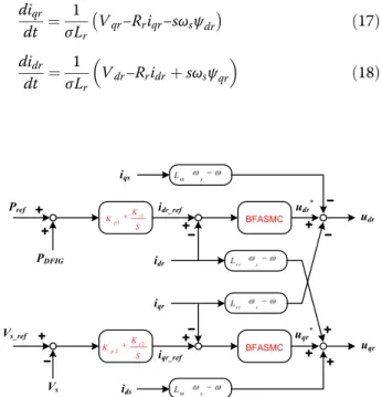
In the vector controlled DFIG system with stator flux orientation,ψqs= 0and ψds=ψs. Modifying the dynamics
given in (1–2) in terms of rotor currents:
diqr dt ¼
1 σLr
Vqr−Rriqr−sωsψdr
ð17Þ didr
dt ¼ 1
σLr Vdr−Rridrþsωsψqr
ð18Þ
Fig. 1DFIG based wind energy system connected to the grid
The reference rotor current idr_ref is generated using
PI controller by comparing reference and actual active powers while the reference current iqr_ref is generated
using another PI controller using terminal voltage error. Now these currents are compared with the actual currents and current errors are generated as given (19) & (20).
ed¼idr−idr ref ð19Þ
eq¼iqr−iqr ref ð20Þ
Because of the features like chattering free, finite time convergence and simplicity in design, current controllers are designed with BFASMC.
For the design of control input in d-axis loop, the sliding surface is selected as:
ρd¼ed ð21Þ
Taking the derivative of (21) and from (17), the error dynamics ofρdare given as:
_ ρd¼
1
σLr Vdr−Rridrþsωsψqr
−_idr ref þφd ð22Þ whereφdrepresents unmodelled dynamics and paramet-ric variations.
Now modifying the error dynamics in (22) as:
_
ρd¼udþϕd ð23Þ
where
ud¼ 1 σLr
Vdr−Rridrþsωsψqr
ð24Þ
andϕdis the cumulative disturbance.
From (11), the control input required to stabilize the error in fixed time is given by (25)
ud¼−K^dr ρd sign ρd
ð25Þ
Fig. 3Modified grid side controller
c 2KV/25KV
2KV/25KV 2KV/25KV
575V/ 25KV
9MVA 2KV 9MVA
2KV 9MVA
2KV 1 9MVA 575V
2
3
4 5 6
7
8
c
Area-1 Area-2
Fig. 4Benchmark multi-machine power system
0
10
20
−0.5 0 0.5 −1 −0.5 0 0.5 1
time in s ψqs
ψ ds
Fig. 53-D plot of flux linkages w.r.t time for a three-phase fault at bus 4
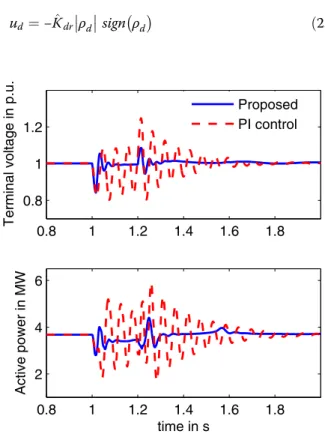
0.8 1 1.2 1.4 1.6 1.8
0.8 1 1.2
Terminal voltage in p.u.
0.8 1 1.2 1.4 1.6 1.8
2 4 6
time in s
Active power in MW
Proposed PI control
Fig. 6Terminal voltage and active power deviations for a three-phase fault at bus 4
where
^
Kdr¼
ρd
Γd−ρd
ð26Þ From (24),
Vdr ¼σLrudþRridr−ωslψqr ð27Þ For the design of control input in q-axis loop, the sliding surface is chosen as:
ρq¼eq ð28Þ
Taking the derivative of (28) and from (18),
_ ρq¼
1
σLr Vqr−Rriqr−ωslψdr
−_iqr refþφq ð29Þ
whereφqrepresents unmodelled dynamics and paramet-ric variations.
Let
uq¼ 1
σLr Vqr−Rriqr−ωslψdr
ð30Þ
Modifying error dynamics in (30) as:
_
ρq¼uqþϕq ð31Þ
From (31), the control input required to stabilize the error in fixed time is:
uq¼−K^qrρqsign ρq ð32Þ 0.8 1 1.2 1.4 1.6 1.8 2
1160 1180 1200 1220 1240 1260 1280 1300
time in s
DC link voltage in V
Proposed method PI Control
Fig. 7DC voltage for a three-phase fault at bus 4
1 1.1 1.2 1.3 1.4 1.5 0.8
1 1.2
Terminal voltage in p.u.
1 1.1 1.2 1.3 1.4 1.5 0
2 4 6
time in s
Active power in MW
Proposed FOSMC
Fig. 8Comparison of the proposed method with FOSMC
0.2 0.2005 0.201 0.2015 0.202 0.2025 0.203 −0.5
0 0.5
time in s
control input
u dd
Fig. 9Control chattering with FOSMC. Red color line indicates FOSMC and the blue one indicates the proposed method
−1.5 −1 −0.5 0 0.5 1 1.5 −1.5
−1 −0.5 0 0.5 1 1.5
ψds
ψ qs
where
^
Kqr¼
ρq
Γq−ρq
ð33Þ From (32),
Vqr ¼σLruqþRriqrþωslψdr ð34Þ The proposed idea of rotor side converter control can be viewed from Fig.2.
A similar procedure is followed for the design of grid side control as shown in Fig. 3. DC link voltage
is compared with the reference voltage and voltage error is given to PI controller which generates the reference current idg_ref. BFASMC is used in the
de-sign of the current control.
Remarks: The control parametersΓq,Γdare selected
based on the maximum possible current errors eqand ed
respectively.
5 Results and discussion
The proposed composite sliding mode control is evalu-ated by testing in a simulevalu-ated environment MATLAB/ Simulink. In order to observe the robustness of the proposed control idea, it is tested for various test conditions for a benchmark multi-machine power sys-tem model. This benchmark syssys-tem is a modified two
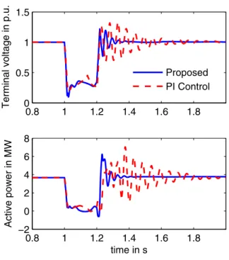
0.8 1 1.2 1.4 1.6 1.8
0 0.5 1 1.5
Terminal voltage in p.u.
0.8 1 1.2 1.4 1.6 1.8
−2 0 2 4 6 8
time in s
Active power in MW
Proposed PI Control
Fig. 11Response of DFIG for a fault at bus 5
0.8 1 1.2 1.4 1.6 1.8
800 900 1000 1100 1200 1300 1400 1500 1600
time in s
DC link voltage in V
Proposed PI Control
Fig. 12DC link voltage for a three-phase fault at bus 5
20 25 30 35 40
5 10 15
Wind speed in m/s
20 25 30 35 40
3.4 3.6 3.8 4 4.2
time in s
Active power
Fig. 13Response of DFIG system for variable wind speed
26 26.5 27 27.5 28 −4
−3 −2 −1 0 1 2 3x 10
−3
time in s
Active power error in MW
PI Control Proposed
Fig. 14Active power error for variable wind speed
area Kundur’s model [16, 17], (Feng [3]) with one of the synchronous generator replaced with DFIG based wind energy system as shown in Fig. 4. The detailed report of the benchmark system is given in [19].
5.1 A three-phase fault on bus 4
As the power system is a large distributed system, three phase faults on transmission lines are common. A three-phase is applied at bus 4 at 1 s with a fault resistance of 1Ω. The fault is cleared after 0.2 s. The wind speed is assumed constant at 10 m/s. The functioning of the composite control can be visualized by observing the flux linkages as shown in Fig.5. Under the pre-fault condi-tion, flux linkages are distortion free. The flux distortions are present during the transients and the controller brings the system to the steady state.
The proposed idea is compared to conventional PI control. The active power deviations and terminal volt-age deviations are captured in Fig. 6. With PI control, the active power and terminal voltage oscillates and set-tles after 1.8 s. Yet, with the proposed composite sliding mode control, the active power and terminal voltage oscillations are less and settles faster with less peak overshoot. The peak overshoot and settling time of DC link voltage with the proposed method are improved con-siderably when compared with the conventional PI control as shown in Fig. 7. One of the major drawback with FOSMC is the selection of optimum control gain value. The performance of the DFIG system with FOSMC with high control gain is depicted in Fig. 8 and the same is compared with the proposed method. Control chattering is another concern with FOSMC, but with the proposed approach, control chattering is minimized. This is because, when the sliding surface ρ is approaching zero, control input tends to zero. The control inputudwith FOSMC has
undesirable oscillations and this can be visualized in Fig.9.
5.2 A three-phase fault at bus 5
A three-phase fault is applied at bus 5 with fault resistance of 1Ω. The flux linkage deviations are plotted in Fig.10. As the fault is closer to the wind generation system, the distor-tions are enormous. After the fault, the active power and terminal voltage deviations are less with the proposed ap-proach compared with the conventional apap-proach. This can be visualized in Fig. 11. A similar result can be observed with the DC link voltage as shown in Fig.12.
5.3 Variable wind speed
The power output of the wind energy system varies con-tinuously with time because of the stochastic nature of wind. Hence, the DFIG system is simulated with variable wind speed profile and the corresponding active power is shown in Fig.13. The zoomed plot of active power error is
shown in Fig.14and it shows the efficacy of the proposed approach.
6 Conclusions
This paper presents a modified vector controlled DFIG system. The inner current loop with PI control in the conventional system is replaced with adaptive sliding mode control where the control gains are updated based on semi-definite barrier function. The proposed composite control is evaluated for a benchmark multi-machine power system model for various operating conditions. The pro-posed method has shown a considerable effect on the power system stability when compared to the conventional PI controller. The proposed method is robust to large dis-turbances like a three-phase fault.
Acknowledgements
Not applicable.
Funding
The authors declare that the research is not funded by any Government/ Private institution/agency.
Availability of data and materials
All the data is given in the paper or properly cited wherever necessary.
Authors’contributions
TSLVAR contributed to analysis, modelling, manuscript preparation, revision and typesetting of the manuscript. TSLVAR read and approved the final manuscript.
Competing interests
The authors declare that they have no competing interests.
Received: 22 August 2018 Accepted: 17 February 2019
References
1. Beltran, B., Benbouzid, M. E. H., & Ahmed-Ali, T. (2012). Second-order sliding mode control of a doubly fed induction generator driven wind turbine.IEEE Transactions on Energy Conversion, 27(2), 261–269.https://doi.org/10.1109/ TEC.2011.2181515.
2. Evangelista, C. A., Pisano, A., Puleston, P., & Usai, E. (2017). Receding horizon adaptive second-order sliding mode control for doubly-fed induction generator based wind turbine.IEEE Trans Control Syst Technol, 25(1), 73–84.
https://doi.org/10.1109/TCST.2016.2540539.
3. Wu, F., Zhang, X.-P., Ping, J., & Sterling, M. J. H. (2008). Decentralized nonlinear control of wind turbine with doubly fed induction generator.IEEE Trans Power Syst, 23(2), 613–621.https://doi.org/10.1109/TPWRS.2008.920073. 4. Hu, J., Nian, H., Hu, B., He, Y., & Zhu, Z. Q. (2010). Direct active and reactive power regulation of DFIG using sliding-mode control approach. IEEE Transactions on Energy Conversion, 25(4), 1028–1039.https://doi.org/10.1109/ TEC.2010.2048754.
5. Javadi, M., Malyscheff, A. M., Wu, D., Kang, C., & Jiang, J. N. (2018). An algorithm for practical power curve estimation of wind turbines. CSEE Journal of Power and Energy Systems, 4(1), 93–102.https://doi.org/10.17775/ CSEEJPES.2016.00980.
6. Kenne, G., Nguimfack Ndongmo, J. D. D., Fochie Kuate, R., & Fotsin, H. B. (2015). An online simplified nonlinear controller for transient stabilization enhancement of DFIG in multi-machine power systems.IEEE Trans Autom Control, 60(9), 2464–2469.https://doi.org/10.1109/TAC.2015.2427591. 7. Lei, Y., Mullane, A., Lightbody, G., & Yacamini, R. (2006). Modeling of the
8. Lin, W., Wen, J., Cheng, S., & Lee, W.-J. (2012). An investigation on the active-power variations of wind farms. IEEE Trans Ind Appl, 48(3), 1087–1094.
https://doi.org/10.1109/TIA.2012.2190817.
9. Liu, X., Han, Y., & Wang, C. (2017). Second-order sliding mode control for power optimisation of DFIG-based variable speed wind turbine.IET Renewable Power Generation, 11(2), 408–418. https://doi.org/10.1049/iet-rpg.2015.0403.
10. Liu, Y., Wu, Q. H., Zhou, X. X., & Jiang, L. (2014). Perturbation observer based multiloop control for the DFIG-WT in the multimachine power system.IEEE Trans Power Syst, 29(6), 2905–2915.https://doi.org/10.1109/ TPWRS.2014.2308900.
11. Mishra, Y., Mishra, S., Tripathy, M., Senroy, N., & Dong, Z. Y. (2009). Improving stability of a DFIG-based wind power system with tuned damping controller.IEEE Transactions on Energy Conversion, 24(3), 650–660.https://doi. org/10.1109/TEC.2009.2016034.
12. Wang, N., Kang, C., Ren, D. (2015).Large-Scale Wind Power Grid Integration: Technological and Regulatory Issues. Elsevier.
13. Obeid, H., Fridman, L. M., Laghrouche, S., & Harmouche, M. (2018). Barrier function-based adaptive sliding mode control. Automatica, 93, 540–544.
https://doi.org/10.1016/j.automatica.2018.03.078.
14. Phan, V. T., & Lee, H. H. (2012). Performance enhancement of stand-alone DFIG systems with control of rotor and load side converters using resonant controllers.IEEE Trans Ind Appl, 48(1), 199–210.https://doi.org/10.1109/TIA. 2011.2175883.
15. Shtessel, Y., Edwards, C., Fridman, L., & Levant, A. (2014).Sliding mode control and observation. New York: Springer New York. https://doi.org/10.1007/978-0-8176-4893-0.
16. Tang, Y., Ju, P., Member, S., He, H., Qin, C., & Wu, F. (2013). Optimized control of DFIG-based wind generation using sensitivity analysis and particle swarm optimization.IEEE Transaction Om Smart Grid, 4(1), 509–520doi.org/10.1109/ TSG.2013.2237795.
17. Tummala, A. S. L. V., Alluri, H. K. R., & Ramanarao, P. V. (2018). Optimal control of DFIG wind energy system in multi-machine power system using advanced differential evolution. IETE J Res, 1–12. https://doi.org/ 10.1080/03772063.2018.1466732.
18. World Wind Energy Market Update. (2017).Navigant research. Retrieved fromhttps:// www.navigantresearch.com/research/world-wind-energy-market-update-2017
19. Wu, F. (2009). Modelling and Control of Wind and Wave Energy Conversion.
Ph.D. Thesis Submitted to the University of Birmingham, (January).