AUSTRALIAN JOURNAL OF BASIC AND
APPLIED SCIENCES
ISSN:1991-8178 EISSN: 2309-8414 Journal home page: www.ajbasweb.com
Open Access Journal
Published BY AENSI Publication
© 2016 AENSI Publisher All rights reserved
This work is licensed under the Creative Commons Attribution International License (CC BY).
http://creativecommons.org/licenses/by/4.0/
To Cite This Article: Ani Melfa Roji M, Kirubaveni S, Radha S, Sreeja B.S., Design of Triangular Shaped Piezoelectric Vibration Energy Harvester for MEMS Applications. Aust. J. Basic & Appl. Sci., 10(5): 29-40, 2016
Design of Triangular Shaped Piezoelectric Vibration Energy Harvester for
MEMS Applications
1
Ani Melfa Roji M, 2Kirubaveni S, 3Radha S, 4Sreeja B S
1PG Scholar, Department of Electronics and Communication Engineering, SSN College of Engineering, Chennai, India 2Assistant Professor, Department of Electronics and Communication Engineering, SSN College of Engineering, Chennai, India 3
Professor and HOD, Department of Electronics and Communication Engineering, SSN College of Engineering, Chennai, India 4
Associate Professor, Department of Electronics and Communication Engineering, SSN College of Engineering, Chennai, India
Address For Correspondence:
Ani Melfa Roji M, PG Scholar, Department of Electronics and Communication Engineering, SSN College of Engineering, Chennai, India. E-mail: animelfarojim@gmail.com; Phone:+91-8220231931
A R T I C L E I N F O A B S T R A C T
Article history:
Received 12 January 2016 Accepted 22 February 2016 Available online 1 March 2016
Keywords:
Cantilever, Finite Element Analysis,
Maximum Tolerable Amplitude,
MEMS, Piezoelectric Vibration
Energy Harvester, Uniform Strain Distribution
Background: The power supply acts a s a major barrier for improvement in MEMS technology. The Piezoelectric Vibration Energy Harvester (PVEH) is a promising solution for development of self powered micro scale devices. The triangular shaped cantilever structure is chosen for designing energy harvester because of its uniform strain distribution and maximum tolerable amplitude. Objective: This paper deals with design of triangular shaped piezoelectric micro scale energy harvester which can harvest maximum energy at low resonant frequency. The proposed harvester have the ability to tolerate maximum load than conventional rectangular one. This harvester is very much useful in micro low power portable electronic devices where replacement of battery is inconvenient. Results: The optimized structure produces 24% increase in stress at a resonant frequency of 177.5 Hz for a mechanical force of 0.005 N/m3 per unit length and hence the obtained potential is raised to 4 times of that of conventional rectangular structure. Conclusion: The structure can be further optimized by changing certain parameters such as length, width and thickness of each layer. It is observed that longer, wider and thinner cantilever beam structure is preferred for the design of efficient energy harvester. In the future, there is a great demand for self powered electronic devices. Because of abundant availability of vibrations in the environment, the piezoelectric vibration energy harvester will become a promising solution to power the wireless micro devices.
INTRODUCTION
Wireless Sensor Networks (WSN) lead to remarkable development in the upcoming fields like vehicle control, continuous monitoring applications, health care and construction of smart buildings (Kim, S., et al., 2013; Mainwaring, A., et al., 2002). Most of these sensors are currently powered by means of chemical batteries and rechargeable batteries. Although we are improving the power capacity of batteries, it is impossible to design a battery which can power a wireless node throughout its lifetime. Replacement of batteries in a periodic way is also inconvenient and expensive. Hence we need an alternative power source to overcome this problem in order to increase the lifespan of these networks.
generally too big. When the size of the harvester is reduced, it becomes expensive. The major goal in designing an energy harvesting device is to achieve high efficiency and high power density for a given mechanical vibrations.
The vibration based generators are designed using three types of transduction mechanisms: electromagnetic, electrostatic and piezoelectric. There are several limitations of using electrostatic transduction mechanism. It needs additional voltage source to generate output power. It also possesses low power density and complicated fabrication process (Beeby, S.P., et al., 2006). The electrical power generated by electromagnetic transduction mechanism will be a function of magnetic field, relative motion, and number of turns of the coil. The generated ac output voltage is limited by various parameters and it is just below 1V.
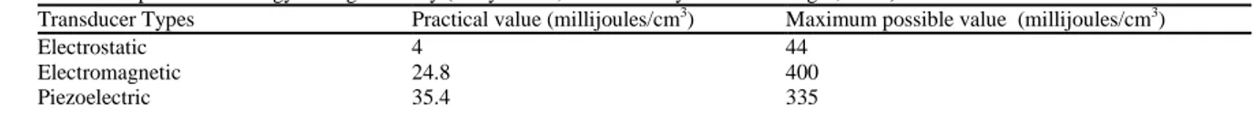
Piezoelectric energy harvester attains much importance among different types of renewable energy sources available in the environment because of its abundant easy availability (Goldfarb, M. and L.D. Jones, 1999; Yoon, H.S., et al., 2005). Because of low cost, simple structure, easy manufacture, and so forth, piezoelectric vibration energy harvesters has been widely used as intermittent power source for MEMS devices. In addition to that, it is not subjected to electromagnetic interference and it can also be easily integrated with MEMS devices. Comparison of different mechanical vibration energy harvesters based on energy storage density is given in Table 1.
Table 1: Comparison of Energy Storage Density (Jessy Baker, Shad Roundy and Paul Wright, 2005)
Transducer Types Practical value (millijoules/cm3) Maximum possible value (millijoules/cm3)
Electrostatic 4 44
Electromagnetic 24.8 400
Piezoelectric 35.4 335
2 Piezoelectric Vibration Energy Harvesting:
The PVEH converts mechanical vibration energy into alternating electrical energy (alternating current). This alternating current (AC) output is electronically converted into direct current (DC) by means of power conditioning circuitry. This DC power can replace the need for batteries and costly battery maintenance to power remote systems. Piezoelectric energy harvester works on the basic principle of piezoelectric effect. When a mechanical stress is applied over a material, it will generate electric charge. Such materials are called as piezoelectric materials. This effect is called as piezoelectric effect. The constitutive equations (Junjun Ding, et al., 2013) of piezoelectric energy harvesting can be written as
=
E T d
d s
D S
ε (1)
where S is the strain in the piezoelectric material, D is the electrical displacement, s is compliance, d is piezoelectric strain coefficient, ε is the dielectric, T is the stress, and E is the electric field.
(a) (b)
Fig. 1: Operating Modes of Piezoelectric Structure (Priya, S., 2007) (a) d31 Mode (b) d33 Mode
3 Mathematical Modeling of Triangular Harvester:
In order to justify the simulated results the mathematical model of the triangular shaped piezoelectric vibration energy harvester is provided.
3.1 Resonant Frequency:
The resonant frequency of a general micro cantilever is given by (2) (Kim, H., et al., 2008)
∑
1 = 2 2 1 2 1= in i i
n
n E I
m l v
π
f (2)
where fn refers to nth resonant frequency, vn is the nth dimensionless eigen value (where the dimensionless eigen value of first order, v1=1.875), l is the length of the cantilever beam, m is the mass of the cantilever structure, Ei is the Young’s modulus of the ith layer, Ii is the moment of inertia of the cross section of ith layer of the cantilever and n refers to number of layers.
The mass of the triangular cantilever structure is obtained as
∑
1 = 2= n
i tiρi
lw
m (3)
where ρi is the density of the ith layer, w is the width of the cantilever beam and tis the thickness of the cantilever beam.
The moment of inertia of cross section of triangular cantilever beam is found by using the moment of inertia of rectangle because the cross section of the triangular beam is of rectangular shape. The moment of inertia of rectangle is given by
12 =
3 wt
Irectangle (4)
The width of the cantilever reduces as we move towards the free end while the width of the beam remains constant from fixed end till the free end in case of rectangular beam. Hence, the moment of inertia of cross section at a distance ‘x’ from the fixed end of a triangular structure is as follows:
12 ) ( 3 t x w
Ix = (5)
Thus, the moment of inertia of cross section of triangular structure is derived as
) l w ( lt I 2 24 = 3 (6)
Hence, the frequency of the triangular harvester is simplified as follows
− ∏ = w l Et l v f n n 2 12 2 1 2 2 2 ρ (7) 3.2 Displacement:
The deflection of the cantilever beam can be calculated by Stoney’s formula
2 2 ) 1 ( 3 Et l ϑ σ
δ = − (8)
where δ is the deflection of the cantilever beam, σ is the stress and υ is the Poisson’s ratio. The deflection can also be calculated using (9)
3.3 Stress:
When a mechanical force is applied on a beam, a stress is created. It causes the free end of the beam to displace from its original position. The relationship between curvature of the deflected beam and the applied mechanical stress is given by
δ
F R
κ = 1 = (10)
where κ is the curvature and R refers to radius of curvature of bending arc formed due to deflection of the cantilever beam. On substituting (8) in (10) we get
2 2 ) 1 ( 3 l FEt ϑ σ κ −
= (11)
Now, substituting (9) in (11), we get
3 8 =
l EI
κ (12)
The expression for stress can be derived by equating (11) and (12).
I l Ft ) 1 ( 24 2 ϑ
σ = − (13)
3.4 Strain:
For a homogeneous isotropic linear elastic material, the stress is related to the strain by
E
ε
σ
=
(14)Hence, the strain (ε) of the cantilever beam can be estimated by using
E σ
ε = (15)
From the above, expression, it is clear that the train is directly proportional to applied mechanical stress of the cantilever.
3.5 Power:
In case of micro energy harvester, the power output is proportional to the square of the electromechanical coupling coefficient (k31) and inversely proportional to that of resonant frequency (Goldfarb, M. and L.D. Jones, 1999) as in (16).
2 2 2
31
∝ .Q
ency sonatFrequ Re on Accelerati . m . k
Poweroutput eff
(16)
where k31 is electromechanical coupling coefficient, meff is effective mass and Q is the quality factor. In order to achieve maximum power, we have chosen a material with high electromechanical coupling coefficient (PZT-5H). The normalized power density of the PVEH (Frank Goldschimdtboeing and Peter woias, 2008) is given as
2 × = on Accelerati Volume Power ty PowerDensi
Normalized output (17)
4 Reason for Selection of Triangle Shape:
The triangular beam exhibits high power, energy and efficiency when compared to that of the rectangular beam under the condition of matching impedance. The advantage is that the efficiency is improved with same PZT area (Kim, S., et al., 2013). The strain is the most important factor which affects the amount of electrical energy generation. The rectangular cantilever has maximum strain only at the fixed end of the beam. It reduces the efficiency of converting the vibration energy to electrical energy to be minimum. While in case of triangular one, the maximum strain is uniformly distributed over the entire length of the cantilever beam. It is because of the fact that, maximum strain at all points of the beam remains constant only when the ratio of width to distance from free end is of fixed value. For a triangular harvester, the width increases as distance from free end increases which yields uniform strain distribution. It leads to maximum stress which in turn causes maximum deformation. Hence maximum energy is harvested. The durability is maintained same as that of the conventional rectangular one.
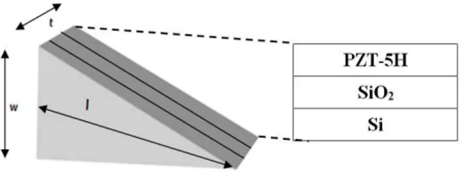
5 Proposed Triangular Structure: 5.1 Definition:
The proposed model is composed of three layers. The harvester structure is triangular in shape. The cantilever structure is designed with rectangular cross section whose width value decreases from one end to the other end. The topmost layer is the piezoelectric layer and the bottom two layers are substrate layer The chosen material for piezoelectric layer is PZT-5H because of its better properties when compared to other piezoelectric material properties (especially its high electromechanical coupling coefficient) as discussed in chapter 1. Since the piezoelectric materials are normally brittle, it cannot be used directly for designing an energy harvester. Hence a vibration energy harvester is usually composed of a piezoelectric material and substrate which is made of solid material. The middle layer is made of silicon dioxide. The bottom layer is composed of silicon. The structure of proposed energy harvester is shown in Fig. 2.
Fig. 2: Structure of Proposed Harvester
The cantilever structure is chosen because it has the ability to achieve maximum deformation and maximum stress under the same conditions. At the same time, it also exhibits minimum resonant frequencies. The dimension of the proposed triangular cantilever structure is given in Table 2.
Table 2: Dimension of Cantilever Beam
Parameter Symbol Dimensions (µm)
Length of the cantilever l 5000
Width of the cantilever at the fixed end w 3000
Thickness of the cantilever t 10
Thickness of PZT layer tPZT 4
Thickness of SiO2 layer tSiO2 2
Thickness of Si layer tSi 4
5.2 Device Modeling:
In order to simulate the proposed design of energy harvester, finite element analysis method is used which is the basis of simulation analysis. It is convenient, easy to work and also provide accurate results. Initially, the proposed triangular cantilever structure is modeled using COMSOL MULTIPHYSIS 5.0 by selecting the piezoelectric devices under physics section.
Fig. 3: Boundary Conditions
The analysis of eigen frequency, displacement and electric potential is done under eigen frequency study. The analysis of von mises stress and strain distribution is performed under stationary study. The Piezoelectric Devices interface combines Solid Mechanics Electrostatics and Multiphysics together with the constitutive relationships required to model piezoelectric device. Both the direct and inverse piezoelectric effects can be modeled using the strain-charge or stress-charge forms and the piezoelectric coupling can also be formulated.
Once the structure is designed, meshing is done in order to divide the entire structure into small areas to get accurate analysis results. Based on the applied force, the structure displaces and it is given by the mode shape structure shown in the fig. 4. The mode shape in an oscillating system is given by the movement of all parts with the same frequency and fixed phase relation. The eigen frequency in this mode gives the resonant frequency. The mode of vibration is characterized by mode shape and the number of modes is based on the varying vibrations.. The different colour in the structure describes the varying value of the displacement, stress, strain and potential with respect to varying frequency in the corresponding mode shapes.
5.3 Simulation Results:
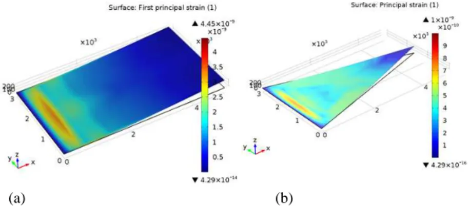
The mode shape is obtained by computing the eigen frequency study. This mode shape gives the eigen frequency (resonant frequency) and displacement of the structure. The mode shape is shown in Fig. 4. The resonant frequency of the proposed structure is obtained as 672.63 Hz. The mechanical force of 0.005 N/m3 per unit length is applied across the piezoelectric material. The stationary analysis of both rectangular and triangular cantilever beam performed. The von misses stress, strain and potential analysis of the structure is observed using the analysis results. The strain analysis for rectangular and triangular structure is obtained as shown in Fig. 5.
Fig. 4: Mode Shape of Proposed Harvester
From the Fig. 5(a), it is clear that there will be large strain concentration only in small area at the base of the cantilever. The tip of the cantilever is hardly strained at all. It shows that the half of the piezoelectric material in the beam remain unutilized. By modifying the geometry of the cantilever beam which allows uniform strain distribution, the average strain can be increased.
(a) (b)
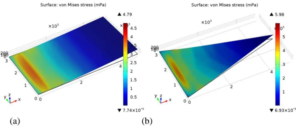
Uniform strain distribution can be achieved by providing a linearly increasing wider cross section of the beam. Hence, triangular shape is suggested to obtain uniform strain distribution. In Fig. 5(b), it is observed that the maximum strain is maintained across the whole cantilever. Hence, it produces maximum stress (Fig. 6) and maximum deformation (Fig.7) in case of triangular harvester which leads to maximum harvested energy.
(a) (b)
Fig. 6: Stress Analysis (a) Conventional Rectangular Structure (b) Proposed Triangular Structure
(a) (b)
Fig. 7: Displaced Structure (a) Conventional Rectangle (b) Proposed Triangle
The obtained potential for the proposed triangular cantilever structure is shown in Fig. 8.
(a) (b)
Fig. 8: Potential Analysis (a) Conventional Rectangular Structure (b) Proposed Triangular Structure
5 Optimization:
5.1 Dimensional Analysis:
The main goal of piezoelectric energy harvesting is that it has to generate maximum power at low frequency (low resonant frequency). This fact has to be taken into consideration and an optimum triangular structure is proposed after a series of analysis is done. Initially, the dimensions of the proposed triangular structure such as length and width of the structure is analyzed. The thickness of each layer of the proposed harvester is varied and hence observes its effect on resonant frequency.
5.1.1 Effect of Cantilever Length:
Frequency analysis and stationary analysis is done with varying length value by keeping the other parameter as constant (w=3000 µm, tPZT=4 µ m, tSiO2=2 µ m, tSi=4 µ m).
Fig. 9: Frequency Vs Cantilever Length
The frequency dependency curve on the cantilever length is given in Fig. 9, which concludes that the length should be as high as possible without violating the design rules. It is observed that the longer cantilever beam structures are suitable for energy harvester design. Hence the optimum length of the harvester is chosen as 8000 µ m.
5.1.2 Effect of Cantilever Width:
To verify the effect of cantilever width in the performance of the triangular harvester, both frequency and stationary analysis is performed by varying the width of the cantilever alone keeping other parameters as constant (l=8000 µm, tPZT=4 µm, tSiO2=2 µ m, tSi=4 µ m).
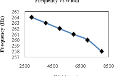
Fig. 10: Frequency Vs Width
The frequency dependency curve on width of the cantilever beam is given in Fig. 10. But, we can observe that change in width of the cantilever doesn’t have adverse effect on resonant frequency of the cantilever. The resonant frequency of the structure is gradually decreasing when we increase the width of the cantilever. Hence, slight improvement in performance is achieved by using wider cantilever.
5.1.3 Effect of Piezoelectric Layer Thickness:
The frequency response of the triangular structure with respect to change in cantilever width keeping other parameter constant (l=8000 µm, w=8000 µm, tSiO2=2 µ m, tSi=4 µ m) is analyzed.
The frequency dependency curve on varying width is shown in Fig. 11. The increase in efficiency of the proposed structure is observed when there is a decrease in thickness of piezoelectric layer. So, cantilever with minimum PZT layer thickness is preferred for energy harvester design. Hence, the optimized thickness of PZT is taken as 3 µ m.
5.1.4 Effect of SiO2 Layer Thickness:
Frequency analysis and stationary analysis is done with varying length value by keeping the other parameter as constant (l=8000 µ m, w=8000 µm, tPZT=3 µ m, tSi=4 µ m).
Fig. 12: Frequency Vs tSiO2
Figure 12 clearly shows that minimum frequency condition is achieved in case of Silicon dioxide layer with minimum thickness. Hence, SiO2 layer thickness should be reduced for optimum energy harvester design. The optimum thickness of SiO2 layer is chosen as 1 µ m.
5.1.5 Effect of Silicon Layer Thickness:
Finally, to verify the effect of silicon layer thickness in the performance of the triangular harvester, both frequency and stationary analysis is performed by varying the thickness of the silicon layer alone keeping other parameters as constant (l=8000 µm, w=8000 µ m, tPZT=3 µ m, tSiO2=1 µ m).
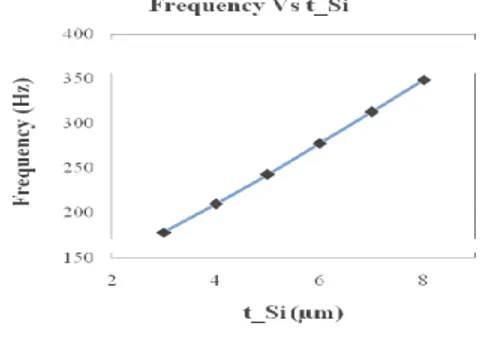
Fig. 13: Frequency Vs tSi
The variation in resonant frequency with respect to change in thickness of Si layer is shown in fig. 13. The Silicon layer thickness should also be minimum to achieve low resonant frequency. So, we can conclude that for designing an efficient energy harvester with minimum resonant frequency the thickness of the cantilever should be as minimum as possible.
5.2 Simulation of Optimized Structure:
Based on the results that are obtained from the above geometrical and dimensional analysis, it is observed that triangular structure exhibits better performance in energy harvesting applications because of its uniform strain distribution. It leads to maximum deformation and thus maximum harvested energy. From the analysis results, the dimensions of the optimized structure are selected as given in Table 3.
Table 3: Dimensions of Optimized Cantilever Beam
Parameter Symbol Dimensions (µm)
Length of the cantilever l 8000
Width of the cantilever at the fixed end w 8000
Thickness of the cantilever t 7
Thickness of PZT layer tPZT 3
Thickness of SiO2 layer tSiO2 1
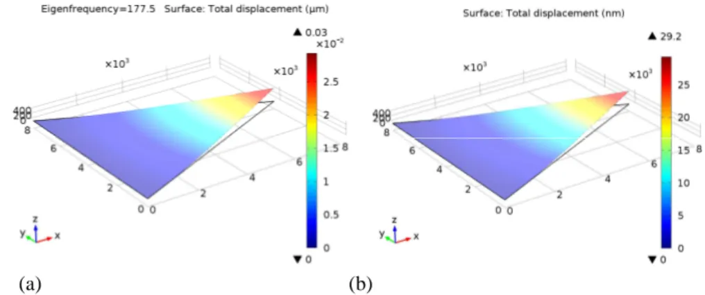
The optimized structure is simulated using COMSOL MULTIPHYSICS 5.0. The eigen frequency analysis is performed. The obtained mode shape and resonant frequency of the optimized structure is shown in Fig. 14(a). Then, the stationary analysis is done. The displacement is also observed for the optimized harvester as shown in Fig. 14(b).
(a) (b)
Fig. 14: (a) Mode Shape and (b) Displacement of Optimized Structure
When a mechanical force of 0.005 N/m2 is applied across the piezoelectric material and the stationary analysis is done, the obtained stress and strain distribution is shown in Fig. 15(a) and Fig. 15(b) respectively.
(a) (b)
Fig. 15: (a) Stress Analysis and (b) Strain Analysis
The obtained potential is observed in Fig. 16.
Fig. 16: Potential Analysis of Optimized Structure
The calculated and simulated results of the optimized structure are compared and tabulated in Table 4.
Table 4: Comparison of Simulated and Modeled Results
Parameter Unit Simulated Value Modeled Value
Resonant Frequency Hz 177.5 177
Displacement nm 29.2 28.85
Conclusion:
The harvester should have triangular shape because of its uniform strain distribution to harvest maximum energy. It causes maximum stress which in turn results in maximum deformation. The structure can be further optimized by changing certain parameters such as length, width and thickness of each layer. It is observed that longer, wider and thinner cantilever beam structure is preferred for the design of efficient energy harvester. The optimized structure experiences 24% more stress than that of rectangular cantilever structure because of uniform strain distribution which in turn causes maximum displacement. Hence, the potential is increased to 4 times at a resonant frequency of 177.5 Hz when a mechanical force of 0.005 N/m3 is applied per unit length of the cantilever structure. In the future, there is a great demand for self powered electronic devices. Because of abundant availability of vibrations in the environment, the piezoelectric vibration energy harvester will become a promising solution to power the wireless micro devices.
REFERENCES
Amat A. Basari, Sosuke Awaji, Song Wang, Seiji Hashimoto, Shunji Kumagai, Kenji Suto, Hiroaki Okada, Bunji Homma, Wei Jiang and Shuren Wang, 2014. "Shape effect of piezoelectric energy harvester on vibration power generation", Journal of Power and Energy Engineering, 2: 117-124.
Beeby, S.P., M.J. Tudor and N.M. White, 2006. "Energy harvesting vibration sources for Microsystems applications", Meas Sci Technol, 17(12): R175.
Bell, L.E., 2008. "Cooling, heating, generating power, and recovering waste heat with thermoelectric systems", Science, 321(5895): 1457-1461.
Chen, 2009. "Analytical and experimental study on vibration energy harvesting behaviors of piezoelectric cantilevers with different geometries", IEEE Conference on Sustainable Power Generation and Supply.
Francesc Moll and Loreto Mateu, 2005. "Optimum piezoelectric bending beam structures for energy harvesting using shoe inserts", Journal of Intelligent Material Systems and Structures, 16.
Frank Goldschimdtboeing and Peter woias, 2008. "Characterization of different beam shapes for piezoelectric energy harvesting", Journal of Micromachines and Microengineering.
Goldfarb, M. and L.D. Jones, 1999. "On the efficiency of electric power generation with piezoelectric ceramic", Transactions on ASME, Journal of Dynamic Systems Measurements and Control, 121: 566-571.
Itou, Akihiro, Tetsuya Asano, Daijiro Inoue, Hidekazu Arase, Akio Matsushita, Nobuhiko Hayashi, Ryutaro Futakuchi, 2014. "High-efficiency thin and compact concentrator photovoltaics using micro-solar cells with via-holes sandwiched between thin lens-array and circuit board", Japanese Journal of Applied Physics, 53: 4S.
Jessy Baker, Shad Roundy and Paul Wright, 2005. "Alternative geometries for increasing power density in vibration energy scavenging for wireless sensor networks", 3rd International Energy Conversion Engineering Conference.
Jeon, Y.B., R. Sood, J.H. Jeong, S.G. Kim, 2005. "MEMS power generator with transverse mode thin film PZT", Sensors Actuators A, 122(1): 16-22.
Jingyan, 2008. ‘Electrostatically actuated cantilever with SOI-MEMS parallel kinematic XY stage’, Journal of Microelectromechanical Systems.
Junjun Ding, Vinod R. Challa, Prasad M.G. and Frank T. Fisher, 2013."Vibration energy harvesting and its application for nano and micro robotics", Micro/Nano-Robotics for Biomedical Applications.
Kim, H., V. Bedekar, R.A. Islam, W.H. Lee, D. Leo and S. Priya, 2008. "Laser-machined piezoelectric cantilevers for mechanical energy harvesting energy harvesting", IEEE Transactions on Ultrasonics Ferroelectrectrics Frequent Control., 55(9): 1900.
Kim, S., W.W. Clark and Q.M. Wang, 2003. "Piezoelectric energy harvesting using a diaphragm structure", Proc. SPIE, 5055: 307-318.
Mainwaring, A., J. Polastre, R. Szewczyk and D. Culler, 2002. "Wireless sensor networks for habitat monitoring", Proc. of ACM Workshop on Sensor Networks and Applications, pp: 88-97.
Marzencki, M., Y. Ammar and S. Basrour, 2007. "Integrated power harvesting system including a MEMS generator and a power management circuit", Sensors and Actuators A, pp: 145-146; 363-370.
Mounika Reddy, V. and G.V. Sunil Kumar, 2013. "Design And Analysis of microcantilevers with various shapes using COMSOL Multiphysics software", International Journal of Emerging Technology and Advanced Engineering, ISSN 2250-2459, 3: 3.
Poria, D., Monika, R. Sharma, D. Rohilla and M. Kumar, 2012. "Modelling and Simulation of vibration energy harvesting of MEMS device based on epitaxial piezoelectric thin film", International Journal of Advanced Research in Computer Science and Software Engineering.
Priya, S., 2007. "Advances in energy harvesting using low profile piezoelectric transducers”, Journal of Electroceramics, 19(1): 167-184.
microcantilever sensor for biochemical sensing applications", Journal of Physics D: Applied Physics.
Salem Saadon and Othman Sidek, 2013. "Shape optimization of cantilever–based MEMS Energy Harvester for low frequency applications", UKSim 15th International Conference on Computer Modeling and Simulation.
Shen, D., J.H. Park, J.H. Noh, S.Y. Choe, S.H. Kim, H.C. Wikle Iii and D.J. Kim, 2008. "The design, fabrication and evaluation of a MEMS PZT cantilever with an integrated Si proof mass for vibration enrgy harvesting’, Journal of Micromech Microengineering, 18(5): 055017.
Shen, D., J.H. Park, J.H. Noh, S.Y. Choe, S.H. Kim, H.C. Wikle Iii and D.J. Kim, 2009. "Micromachined PZT cantilever based on SOI structure for low frequency vibration energy harvesting", Sensors Actuators Physics A: 154(1): 103-108.