Earth-Air Heat Exchanger Design for Achieve Energy Saving in
HVAC System
Farivar Fazelpour
(1), Reza Asnaashari
(2)(1)
Department of Energy System Engineering Faculty of Engineering, Islamic Azad University–
South Tehran Branch, Tehran, Iran.
F_Fazelpour@azad.ac.ir
(2)
Department of Energy System Engineering Faculty of Engineering, Islamic Azad University–
South Tehran Branch, Tehran, Iran.
St_r_asnaashari@azad.ac.ir, (+98) 912 33 90 497, Corresponding author
Abstract
One of the most important problems in the world is increasing energy consumption by last a few years. According to limited resources of energy in each countries they have to find to solve this problem. Each countries choose several type of solution for decreasing residential building energy consumption. So ongoing researches are developing a new device called Earth-Air Heat Exchanger (EAHE) aimed at achieving higher efficiency and improved economic competitiveness. One possible way to optimize energy usage is the application of a natural Pre heat/cool coil in a heating, ventilation, air conditioning (HVAC) system. Where, the usage of EAHE is one of the technical and economical ways to reduce energy consumption. In this paper, we attempted to apply one approaches for providing suitable air temperatures for using in HVAC system and improve the overall efficiency of system. For achieve this target we most use two line pipe in 1.5m under the grand surface and cover with soil. In transition season we can use only the outdoor air passes through the EAHE for direct using in air conditioning system of building. When the system is operating properly we achieve maximum decreasing of energy consumption which can be give us at least 40% energy saving in HVAC system.
Key Words:
Energy Saving; Earth Air Heat Exchanger (EAHE); Heating, Ventilation and Air Conditioning (HVAC); Heat transfer; Air Flow.
1. Introduction
Global energy consumption is diffusely increasing. In general, people around the world use energy to increase their comfort level. Concerns exist regarding the current rate of energy consumption, and the non-sustainability of energy use patterns, especially in relation to the depletion of fossil fuel resources. These concerns have led to significant actions in recent years in many countries aimed at reducing energy consumption, including austerity measures, utilization of advanced engineering and technology, improvements in efficiency and avoidance of energy loss, and enhanced energy management procedures. To facilitate such efforts, it is important to understand sector by sector the breakdown of energy consumption. The main energy consumption compartments in many countries include the following:
Building
Industry
Agriculture
Transports
Of Course, in other division energy consumption (losses) compartments include 3 major fields which named: generation losses, handling losses and end user losses which above compartment of energy consumption defined only end user losses. In this paper we will concentrate on a few specifically issues
related to the compartment of building. Before, it is essential to introduce a few detailed statistical data about energy consumption in Iran.
1.1.Energy Consumption Statistics In Iran between 1988 and 2010
The first source of energy consumption in Iran is in building. Therefore, it is in this compartment that an effective action on energy saving could lead to the most intense results. The issue is not only technological any way, but also political as the government itself could play a significant role by supporting suitable policies aimed at teaching people why it is important to save energy and how to contribute in this with every day behaviors. Moreover, depending on the specific use of a building, different solution could be adopted to save energy. In the following graphs it will be display the trend of consumption in the period
examined. Image 1, is about liquid gas consumption in building in Iran over the 1988-2010 period. As it can be seen there is a significant raise that nearly doubled the Image. In fact the liquid gas consumption in Iran increased from 2.09x10⁶ m3 in 1988 to 3.89x10⁶ m3 in 2010. In Image 2, for the same period of observation natural gas consumption in building in Iran can be examined. Also in this case an increasing trend can be met but with a much more significant raise (of an order of magnitude), passing from 2.7x10⁹ m3 in 1988 up to 46.8x10⁹ m3 in 2010. Electrical energy consumption in Iran in the same period is shown in Image 3. As it may be evicted by the preceding
data, reducing energy
consumption in building is the big goal to pursue as this is the compartment that affects so heavily the general Images. Among the many different ways through which one should face such task, hereafter a few ones are listed:
Use of renewable energies
Adoption of energy management procedures
Adoption of intelligent building management systems (BMS) Energy recovery systems buildings
Insulation of exterior walls
A combination of 2 or more items from the above list can be used in one building. In any case every solution must be targeted to a specific building. Many different aspects are to be considered before deciding which the best option to adopt is:
Number of floors
Existing technological plants (HVAC system)
Image 1. Liquid gas consumption in building
Image 2. Natural gas consumption in building
Existing electrical plants Sunlight exposure Building end use
Mechanical and electrical plant consume most of the energy in building. Based on statistics more than 65% of the total amount of energy consumption is due to in HVAC systems and more than 30% of total amount of the energy consumption consume in lighting and power systems. We use natural gas in HVAC system to provide more comfort for people who lives in each building. Each time natural gas or liquid gas is burned to put in operation the in-building plants and devices, not only energy will be consumed but also combustion gases (exhaust
gases from the chimney) go into the environment and pollute the air. Those gases include NOx, SOx and COx and their diffusion causes damages to the atmosphere and the infamous global warming. Raise in CO2 pollution in Iran between 2000 to 2011 is shown in Image 4.
2. Methodology
As described in introduction, we should try to decrease energy consumption in each building with different method. So we use selected method of energy saving in a sample building. Actually this paper is a case study on small scale building and contain result of this study. Then we will see that how to design EAHE for this building and how much energy can be save on it. The sample building which we considered is a normal building in Tehran city that it needs 5000 CFM air for heating or cooling in winter and summer. This building has one air handling unit (AHU) with 5000 CFM air flow capacity for providing standard condition of air temperature. The outlet air of AHU will be divided between the rooms by using an accreted air distribution system and insulated ducts. The outlet air of AHU is named supply air (SA) and air value which back to the AHU from the rooms, is named return air (RA). Amount of RA is up to 80% of SA and not more. So we need to use
some Fresh Air (FA) from the outdoor of building. Amount of FA is at least 20% to 40% depending on building application and some other factors based on recommendation of air conditioning standards (such as ASHRAE). The FA and RA will be mix in mixing box of AHU and after cross filter and coil of the AHU leave it as SA. So we can define below equation for FA, RA and SA (Image 5.)
SA=FA+RA (1) As seen in Image 5. Some value of return air from the building must be leave the air conditioning process to be replaced by fresh air. This exhaust air from the AHU is named Extract Air (EA) and EA is equal to FA. Equation (1) means that increasing the amount of RA value lead to decrease the amount of FA value. But based on standard recommendations the return air value never be 100% and at least 20% of full capacity of air value of AHU providing by FA. Using more value of RA up to 80% of SA is very useful for saving more energy in air conditioning system. The return air require seldom heating/cooling process on it, then we can save a lot of energy which need to cooling or heating 5000 CFM value of air. But Fresh air need to complete heating/cooling process depending on season an ambient air temperature. So increasing of amount of FA lead to use more energy for heating or cooling process on FA. Due to this mater we try to use an EAHE as a natural pre heating/cooling coil to providing suitable temperature of air for achieve less energy consumption in air conditioning system. Currently using pre heat/cool coil and
Image 5. Schematic picture of air handling unit Image 4. CO2 emission in Iran
also using Free Cooling (FC) and Free Heating (FH) in transition seasons are useful and well known ways to achieve more energy saving in HVAC system.
2.1. Analyses of design parameters of EAHE
Fundamentals of EAHE design and other heat exchangers is similar. All of them follow heat transfer rules. In the following we will define heat transfer formulas between soil and EAHE. Before we have to explain about structure of EAHE. The EAHE has simple structure. One, two or more parallel pipe line could be make an EAHE. In other words an EAHE contain one or more pipe line as a heating or cooling coil. All of pipe lines are buried at the certain depth
from the surface of the earth. This depth is depending on soil type, rate of sunlight, prevailing domestic temperature of air, type of the surface of earth and finally heat transfer ratio between the soil and ambient air. So for this project we have buried the pipe at 150 cm depth and the soil taken around the pipe and air can cross along the pipe. A schematic picture of pipe is shown in Image 6. Image 7, Shows more complete view of EAHE system. As seen in this Image, the ambient air inter in to the EAHE from one end of pipe and leave this from other end of pipe and go to the air conditioning system.
2.2. Summer heat transfer
At summer the soil temperature is less than ambient air temperature. So direction of heat transfer is from the ambient air to the soil. In other words heat transfer will be from air to soil which have less temperature. In this situation temperature of outlet air from EAHE is less than inlet air temperature. The following picture (Image 8.) shows summer situation and heat transfer flux direction.
2.3. Winter heat transfer
At winter the soil temperature is higher than ambient air temperature. So direction of heat transfer is from the soil to ambient air. In other words heat transfer will be from the soil to ambient air which have less temperature. In this situation temperature of outlet air from EAHE is more than inlet air temperature. The following picture (Image 9.) shows winter situation and heat transfer flux direction. 2.4. Heat transfer equations
In Image 6. Air flow will be define by following equation:
For calculating pipe diameter we need 3 parameters as follow:
Air velocity across the pipe
Maximum air flow
Pressure drop per 100 feet of pipe
Note: We consider the pipe as a circular duct. So based on career standard about the duct design we should put 1700 fpm to 1800 fpm for main air duct. Now we have air velocity and maximum air flow (5000 CFM) in pipe. So we need to refer to the design diagram for galvanized steel pipe and read pipe diameter ( ) from that. We will see the table of final calculation results in next pages. Heat transfer Image 8. Heat transfer between soil and pipe in summer
(2)
Image 7. Pipe line under grandImage 9. Heat transfer between soil and pipe in winter Image 6. Schematic picture of air flow along pipe
from pipe body to the air will be do bye two ways. First by convection heat transfer and second by conduction heat transfer. So we can use following equation for calculating efficiency of heat transfer along the pipe (EAHE).
In above equation phrase of is conduction heat transfer factor and phrase of is convection heat transfer factor. Because of that the convection heat transfer is very small we can regardless of it and define heat transfer efficiency by below equation.
For calculating Nusselt number, we use Gnielinski equation.
In above equation f is friction factor, Re is Reynolds number and Pr is prandtl number for air. For calculating f we can use below equation.
Also the Reynolds number will be calculate by below equation.
In above equation, is air viscosity and is dynamic viscosity of air. So with using of above equations, we can calculate outlet air temperature from EAHE by below equation.
Efficiency of EAHE can be define by below equation.
Friction of inner wall of pipe will be provide pressure drop along the pipe and calculating of this pressure drop is very important from several aspects which one of them is power of fan motor. Pressure drop will be calculate by following equation:
Also power of fan will be define by following equation:
2.5. Soil temperature calculating
The soil temperature at the certain depth is depending on several parameters as below equation which define in table (VIII).
But another simple equation which have enough accurate and also it will be easier to calculate is needed. So above equation replaced equation 15. This equation has defined base on experience study on soil temperature of Tehran, regarding air temperature in different season along 10 years. This equation define the soil temperature based on ambient temperature only in other word in this equation the soil temperature
(3)
(4)
(5)
(6)
(7)
(8)
(9)
(10)
(11)
(12)
(13)
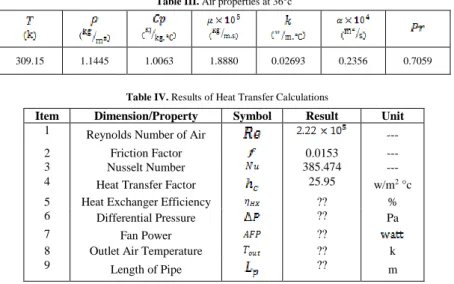
Table III. Air properties at 36°c
Table IV. Results of Heat Transfer Calculations
is function of ambient air temperature. This equation will be change based on changing the depth of soil and below equation will be true for 150cm of depth of soil.
The climate of Tehran is hot and semi-arid. So this city is faced with hot weather in many times of year and regarding this, cooling process is most expansive than heating process, so study on summer situation is most important than other situations and lead to more energy efficiency and decrease cost. The average of maximum air temperature in summer along 40 last years is 36°C which measured by weather organization of Iran. All of calculations are based on 36°C of ambient air temperature.
2.6. Pipe sizing
For achieve better heat transfer and better resistance faced with normal stress, galvanized steel pipe was selected as EAHE. Galvanized pipe help us to reduce surface coarseness of inner wall of pipe and decrease pressure drop of pipe. Use this type of pipe lead to select motor of fan which need less power and electrical energy consumption. According to the previous description and using of ductulator, also with considering the pipe as a circular duct, following tables will be completed.
The results which mentioned in table (I) are based on one pipe line structure of EAHE. But for achieve more efficiency of heat transfer by increase of heat transfer surface, using two pipe line is better. So considering 2 parallel pipe lines of galvanized steel pipe which each of pipe can cross half of maximum air flow from itself is most efficient (Table II). According to the above information heat transfer parameter can be calculate. Table of air properties in 36°C is needed. This table is in thermodynamic books as shown by table (III). Using all of above information help to complete the calculation of heat transfer of EAHE and you can see the results in table (IV).
( 0.7059 0.2356 0.02693 1.8880 1.0063 1.1445 309.15 Unit Result Symbol Dimension/Property Item ---Reynolds Number of Air
1 ---0.0153 Friction Factor 2 ---385.474 Nusselt Number 3 c ° 2 w/m 25.95
Heat Transfer Factor 4
% ??
Heat Exchanger Efficiency 5 Pa ?? Differential Pressure 6 ?? Fan Power 7 k ??
Outlet Air Temperature 8
m ??
Length of Pipe 9
(15)
(16)
Table II. Result of pipe sizing- two line pipe Table I. Result of Pipe Sizing- One line Pipe
As shown, the items number 5 to 9 still remains unknown. Reason of this matter is that all of those parameters are function of length of pipe line so until the optimum pipe length was not calculated, those parameters could not be calculate. To achieve amount of optimum pipe length, using statistical methods is recommended. So a limited domain of pipe length is recommended and review all parameters based on changing length of pipe along that domain. Following domain for pipe length will defined:
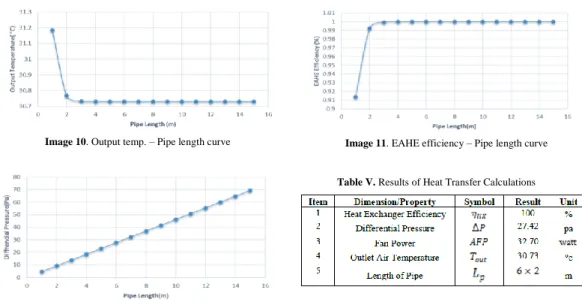
Based on the domain of pipe length and according to the above equation for unknown parameters which mentioned in previous description the following graphs are defined. First diagram (Image 10.) shows output temperature from EAHE regarding to the pipe length changes. Second diagram (Image 11.) shows EAHE efficiency based on pipe length changes. As shown in this Image, the efficiency will be maximum (100%) at 6m of pipe length. 3rd diagram (Image 12.) shows differential pressure of pipe based on pipe length changes. As shown in Image 11. The efficiency of EAHE will be maximum (100%) at 6m of pipe length. It means that the ambient temperature can be increase around 5.27°c and then send this air flow to the air conditioning system and using this way lead to energy saving in air conditioning system. Now unknown factors which mentioned in table (IV), can be calculated and that table can be completed as table (V).
The heat transfer calculation have been complete, it should be noted that the above results are for two pipe line with 6m of length and other pressure drop along the path of air flow must be calculate. How many fitters are in the path of air flow and also how many meter of vertical pipe is there is needed? As shown in Image 13. The answer of this question is in table (V). Based on the information which mentioned in table (VI), accurate calculation of total pressure drop and also calculate motor fan power either can be done. Table (VII), include the results.
(17)
Image 13. Arrangement of parallel pipes under grand
Table V. Results of Heat Transfer Calculations
Table VI. Pipe junction type and quantity
Table VII. Fan power calculation result Image 10. Output temp. – Pipe length curve Image 11. EAHE efficiency – Pipe length curve
3. Conclusion
According to the heat transfer results and also according to this matter that using EAHE decrease the temperature of air around 5.27°c, we can save 44% of energy consumption for cooling FA. The reason of this conclusion is very simple. When we don’t use EAHE the air conditioning system must be cooling the ambient air from 36°c to 24°c (Standard temperature for Tehran’s citizens in summer) but by using of EAHE the air conditioning system must be cooling the FA from 30.73°c to 24°c. Also in transient season we can use EAHE as air conditioning system for providing comfort situation of air temperature without using heating or cooling process by heating/cooling coil of AHU. So in transient season we can save 100% of energy by using of EAHE.
4. References
[1] Xiwang Li n, Jin Wen, Review of building energy modeling for control and operation, Renewable and Sustainable Energy Reviews, 17 May 2014.
[2] Rim Missaouia,b, Hussein Joumaaa,1, Stephane Ploixa, Seddik Bacha, Managing Energy Smart Homes according to Energy Prices: Analysis of a Building Energy Management System, Energy and Buildings, 13.12.2013.
[3] ManojkumarDubey, Dr. J.L.Bhagoria, Dr. Atullanjewar Earth Air Heat Exchanger in Parallel- ConnectionInternational, Journal of Engineering Trends and Technology (IJETT) 2013
[4] Shashank Jain, Application of Earth Air Heat Exchangers in Composite Climate , 28th Conference, Opportunities, Limits & Needs Towards an environmentally responsible architecture Lima (2012). [5] Christophe T’Joen, Liping Liu, M. De Paepe, Comparison of Earth-Air and Earth-Water Ground Tube Heat Exchangers for Residentially Application, International Refrigeration and Air Conditioning Conference at Purdue, July 16-19, 2012
[6] Thomas Woodson, Yézouma Coulibaly and Eric Seydou Traoré, Earth-Air Heat Exchangers for Passive Air Conditioning: Case Study Burkina Faso, Journal of Construction in Developing Countries 2012
[7] Rui Yang, Lingfeng Wang, Multi-objective optimization for decision-making of energy and comfort management in building automation and control, Sustainable Cities and Society, 2012.
[8] Fabrizio Ascione a, Laura Bellia b, Francesco Minichiello, Earth-to-air heat exchangers for Italian climates, Renewable Energy Journal, 21 February 2011
[9] Jyotiprakash Patra, Dr. Partha Sarathi Khuntia, Performance Enhancement of a Dynamic System Using PID Controller Tuning Formulae, IJCSI International Journal of Computer Science Issues, Vol. 8, Issue 5, No 3, September 2011
[10] A. Alper Ozalp, Combined Effects of Pipe Diameter, Reynolds Number and- Wall Heat Flux and on Flow, Heat Transfer and Second-Law - Characteristics of Laminar-Transitional Micro-Pipe Flows, Entropy Journal, 9 March 2010
[11] Marija Trčka, Jan L.M. Hensen, Overview of HVAC system simulation, Automation in Construction, 30 November 2009.
[12] Kwang Ho Lee, Richard K. Strand, The cooling and heating potential of an earth tube system in buildings, Energy and Building, 13 April 2007
[13] Min Zhong Zhao, Simulation of Earth-To-Air Heat Exchanger Systems, 2004
[14] M.De Paepe, A.Janssens, Thermo Hydraulic design of earth air heat exchanger, Energy and Building, 17 July 2002