Implementing IPv6 Multicast
Last Updated: July 31, 2012
Traditional IP communication allows a host to send packets to a single host (unicast transmission) or to all hosts (broadcast transmission). IPv6 multicast provides a third scheme, allowing a host to send a single data stream to a subset of all hosts (group transmission) simultaneously.
• Finding Feature Information, page 1
• Prerequisites for Implementing IPv6 Multicast, page 1
• Restrictions for Implementing IPv6 Multicast, page 2
• Information About Implementing IPv6 Multicast, page 3
• How to Implement IPv6 Multicast, page 18
• Configuration Examples for Implementing IPv6 Multicast, page 75
• Additional References, page 80
• Feature Information for Implementing IPv6 Multicast, page 81
Finding Feature Information
Your software release may not support all the features documented in this module. For the latest caveats and feature information, see Bug Search Tool and the release notes for your platform and software release. To find information about the features documented in this module, and to see a list of the releases in which each feature is supported, see the feature information table at the end of this module.
Use Cisco Feature Navigator to find information about platform support and Cisco software image support. To access Cisco Feature Navigator, go to www.cisco.com/go/cfn. An account on Cisco.com is not required.
Prerequisites for Implementing IPv6 Multicast
• In order to enable IPv6 multicast routing on a router, you must first enable IPv6 unicast routing on the router. For information on how to enable IPv6 unicast routing on a router, refer to Implementing IPv6 Addressing and Basic Connectivity.
• You must enable IPv6 unicast routing on all interfaces.
• This module assumes that you are familiar with IPv6 addressing and basic configuration. Refer to the Implementing IPv6 Addressing and Basic Connectivity module for more information.
Restrictions for Implementing IPv6 Multicast
• IPv6 multicast for Cisco IOS software uses MLD version 2. This version of MLD is fully backward-compatible with MLD version 1 (described in RFC 2710). Hosts that support only MLD version 1 will interoperate with a router running MLD version 2. Mixed LANs with both MLD version 1 and MLD version 2 hosts are likewise supported.
• IPv6 multicast is supported only over IPv4 tunnels in Cisco IOS Release 12.3(2)T, Cisco IOS Release 12.2(18)S, and Cisco IOS Release 12.0(26)S.
• When the bidirectional (bidir) range is used in a network, all routers in that network must be able to understand the bidirectional range in the bootstrap message (BSM).
• IPv6 multicast routing is disabled by default when the ipv6 unicast-routing command is configured. On Cisco Catalyst 6500 and Cisco 7600 series routers, the ipv6 multicast-routing also must be enabled in order to use IPv6 unicast routing.
Platform-Specific Information and Restrictions
In Cisco IOS Release 12.0(26)S, IPv6 multicast is supported on the Cisco 12000 series Internet router only on the following line cards:
• IP Service Engine (ISE): ◦ 4-port Gigabit Ethernet ISE
◦ 4-port OC-3c/STM-1c POS/SDH ISE ◦ 8-port OC-3c/STM-1c POS/SDH ISE ◦ 16-port OC-3c/STM-1c POS/SDH ISE ◦ 4-port OC-12c/STM-4c POS/SDH ISE ◦ 1-port OC-48c/STM-16c POS/SDH ISE • Engine 4 Plus (E4+) Packet-over-SONET (POS):
◦ 4-port OC-48c/STM-16c POS/SDH ◦ 1-port OC-192c/STM-64c POS/SDH
On Cisco 12000 series line cards, the IPv6 multicast feature includes support for Protocol Independent Multicast sparse mode (PIM-SM), Multicast Listener Discovery (MLDv2), static mroutes, and the IPv6 distributed Multicast Forwarding Information Base (MFIB).
Forwarding of IPv6 multicast traffic is hardware-based on Cisco 12000 series IP Service Engine (ISE) line cards that support IPv6 multicast and software-based on all other supported Cisco 12000 series line cards. On Cisco 12000 series ISE line cards, IPv6 multicast is implemented so that if the number of IPv6 multicast routes exceeds the hardware capacity of the ternary content addressable memory (TCAM), the following error message is displayed to describe how to increase the TCAM hardware capacity for IPv6 multicast routes:
EE48-3-IPV6_TCAM_CAPACITY_EXCEEDED: IPv6 multicast pkts will be software switched. To support more IPv6 multicast routes in hardware:
Get current TCAM usage with: show controllers ISE <slot> tcam
In config mode, reallocate TCAM regions e.g. reallocate Netflow TCAM to IPv6 Mcast hw-module slot <num> tcam carve rx_ipv6_mcast <v6-mcast-percent>
hw-module slot <num> tcam carve rx_top_nf <nf-percent> Verify with show command that sum of all TCAM regions = 100% Reload the linecard for the new TCAM carve config to take effect WARNING: Recarve may affect other input features(ACL,CAR,MQC,Netflow)
TCAM is used for IPv6 multicast forwarding lookups. To increase TCAM capacity for handling IPv6 multicast routes, you must use the hw-module slot number tcam carve rx_ipv6_mcast
v6-mcast-Implementing IPv6 Multicast Restrictions for Implementing IPv6 Multicast
percentagecommand in privileged EXEC mode, where v6-mcast-percentage specifies the percentage of TCAM hardware used by IPv6 multicast prefix.
For example, you can change the IPv6 multicast region from 1 percent (default) to 16 percent of the TCAM hardware by reallocating the NetFlow region from 35 percent (default) to 20 percent as follows:
Router# hw-module slot 3 tcam carve rx_ipv6_mcast 16 Router# hw-module slot 3 tcam carve rx_nf 20
On Cisco 12000 series router with IPv6 multicast enabled, if you delete a subinterface with IPv6 configured or if IPv6 is disabled on a subinterface, the associated main interface gets reset.
Note From Cisco IOS Release 12.0(32)SY11 and 12.0(33)S7, deleting a subinterface or disabling IPv6 on a subinterface will reset the associated main interface only if that subinterface is the last subinterface with IPv6 configured under the main interface.
IPv6 multicast hardware forwarding is support on the Cisco Catalyst 6500 and 7600 series in Cisco IOS Release 12.2(18)SXE.
Information About Implementing IPv6 Multicast
• IPv6 Multicast Overview, page 3• IPv6 Multicast Addressing, page 4
• IPv6 Multicast Routing Implementation, page 6
• Multicast Listener Discovery Protocol for IPv6, page 7
• Protocol Independent Multicast, page 9
• Static Mroutes, page 16
• MRIB, page 16
• MFIB, page 16
• IPv6 Multicast VRF Lite, page 17
• IPv6 Multicast Process Switching and Fast Switching, page 17
• Multiprotocol BGP for the IPv6 Multicast Address Family, page 18
• NSF and SSO Support In IPv6 Multicast, page 18
• Bandwidth-Based CAC for IPv6 Multicast, page 18
IPv6 Multicast Overview
An IPv6 multicast group is an arbitrary group of receivers that want to receive a particular data stream. This group has no physical or geographical boundaries--receivers can be located anywhere on the Internet or in any private network. Receivers that are interested in receiving data flowing to a particular group must join the group by signaling their local router. This signaling is achieved with the MLD protocol.
Routers use the MLD protocol to learn whether members of a group are present on their directly attached subnets. Hosts join multicast groups by sending MLD report messages. The network then delivers data to a potentially unlimited number of receivers, using only one copy of the multicast data on each subnet. IPv6 hosts that wish to receive the traffic are known as group members.
Packets delivered to group members are identified by a single multicast group address. Multicast packets are delivered to a group using best-effort reliability, just like IPv6 unicast packets.
IPv6 Multicast Overview
The multicast environment consists of senders and receivers. Any host, regardless of whether it is a member of a group, can send to a group. However, only the members of a group receive the message. A multicast address is chosen for the receivers in a multicast group. Senders use that address as the destination address of a datagram to reach all members of the group.
Membership in a multicast group is dynamic; hosts can join and leave at any time. There is no restriction on the location or number of members in a multicast group. A host can be a member of more than one multicast group at a time.
How active a multicast group is, its duration, and its membership can vary from group to group and from time to time. A group that has members may have no activity.
IPv6 Multicast Addressing
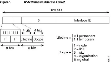
An IPv6 multicast address is an IPv6 address that has a prefix of FF00::/8 (1111 1111). An IPv6 multicast address is an identifier for a set of interfaces that typically belong to different nodes. A packet sent to a multicast address is delivered to all interfaces identified by the multicast address. The second octet following the prefix defines the lifetime and scope of the multicast address. A permanent multicast address has a lifetime parameter equal to 0; a temporary multicast address has a lifetime parameter equal to 1. A multicast address that has the scope of a node, link, site, or organization, or a global scope has a scope parameter of 1, 2, 5, 8, or E, respectively. For example, a multicast address with the prefix FF02::/16 is a permanent multicast address with a link scope. The figure below shows the format of the IPv6 multicast address.
Figure 1 IPv6 Multicast Address Format
IPv6 nodes (hosts and routers) are required to join (receive packets destined for) the following multicast groups:
• All-nodes multicast group FF02:0:0:0:0:0:0:1 (scope is link-local)
• Solicited-node multicast group FF02:0:0:0:0:1:FF00:0000/104 for each of its assigned unicast and anycast addresses
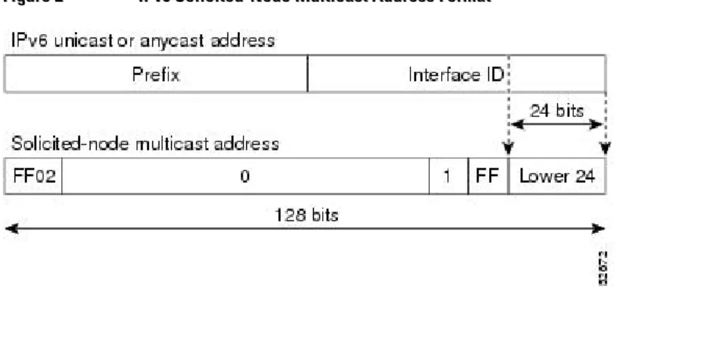
IPv6 routers must also join the all-routers multicast group FF02:0:0:0:0:0:0:2 (scope is link-local). The solicited-node multicast address is a multicast group that corresponds to an IPv6 unicast or anycast address. IPv6 nodes must join the associated solicited-node multicast group for every unicast and anycast address to which it is assigned. The IPv6 solicited-node multicast address has the prefix
FF02:0:0:0:0:1:FF00:0000/104 concatenated with the 24 low-order bits of a corresponding IPv6 unicast or anycast address (see the figure below). For example, the solicited-node multicast address corresponding to
IPv6 Multicast Addressing Information About Implementing IPv6 Multicast
the IPv6 address 2037::01:800:200E:8C6C is FF02::1:FF0E:8C6C. Solicited-node addresses are used in neighbor solicitation messages.
Figure 2 IPv6 Solicited-Node Multicast Address Format
Note There are no broadcast addresses in IPv6. IPv6 multicast addresses are used instead of broadcast addresses.
• IPv6 Multicast Groups, page 5
• Scoped Address Architecture, page 5
IPv6 Multicast Groups
An IPv6 address must be configured on an interface before the interface can forward IPv6 traffic.
Configuring a site-local or global IPv6 address on an interface automatically configures a link-local address and activates IPv6 for that interface. Additionally, the configured interface automatically joins the
following required multicast groups for that link:
• Solicited-node multicast group FF02:0:0:0:0:1:FF00::/104 for each unicast and anycast address assigned to the interface
Note The solicited-node multicast address is used in the neighbor discovery process. • All-nodes link-local multicast group FF02::1
• All-routers link-local multicast group FF02::2
Scoped Address Architecture
IPv6 includes support for global and nonglobal addresses. This section describes the usage of IPv6 addresses of different scopes.
A scope zone, or a simply a zone, is a connected region of topology of a given scope. For example, the set of links connected by routers within a particular site, and the interfaces attached to those links, comprise a single zone of site-local scope.
A zone is a particular instance of a topological region (for example, Zone1’s site or Zone2’s site), whereas a scope is the size of a topological region (for example, a site or a link). The zone to which a particular nonglobal address pertains is not encoded in the address itself, but rather is determined by context, such as the interface from which it is sent or received. Therefore, addresses of a given nonglobal scope may be
IPv6 Multicast Addressing
reused in different zones of that scope. For example, Zone1’s site and Zone2’s site may each contain a node with site-local address FEC0::1.
Zones of the different scopes are instantiated as follows:
• Each link, and the interfaces attached to that link, comprises a single zone of link-local scope (for both unicast and multicast).
• There is a single zone of global scope (for both unicast and multicast), comprising all the links and interfaces in the Internet.
• The boundaries of zones of scope other than interface-local, link-local, and global must be defined and configured by network administrators. A site boundary serves as such for both unicast and multicast. Zone boundaries are relatively static features and do not change in response to short-term changes in topology. Therefore, the requirement that the topology within a zone be "connected" is intended to include links and interfaces that may be connected only occasionally. For example, a residential node or network that obtains Internet access by dialup to an employer’s site may be treated as part of the employer’s site-local zone even when the dialup link is disconnected. Similarly, a failure of a router, interface, or link that causes a zone to become partitioned does not split that zone into multiple zones; rather, the different partitions are still considered to belong to the same zone.
Zones have the following additional properties:
• Zone boundaries cut through nodes, not links (the global zone has no boundary, and the boundary of an interface-local zone encloses just a single interface.)
• Zones of the same scope cannot overlap; that is, they can have no links or interfaces in common. • A zone of a given scope (less than global) falls completely within zones of larger scope; that is, a
smaller scope zone cannot include more topology than any larger scope zone with which it shares any links or interfaces.
• Each interface belongs to exactly one zone of each possible scope.
IPv6 Multicast Routing Implementation
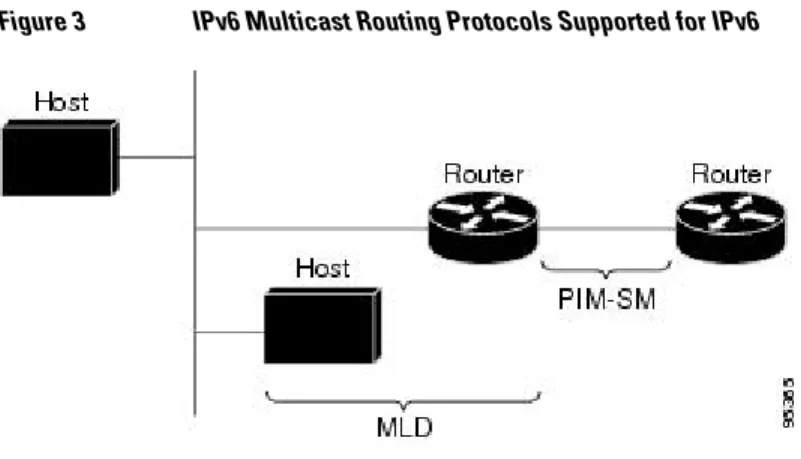
Cisco software supports the following protocols to implement IPv6 multicast routing:
• MLD for IPv6. MLD is used by IPv6 routers to discover multicast listeners (nodes that want to receive multicast packets destined for specific multicast addresses) on directly attached links. There are two versions of MLD: MLD version 1 is based on version 2 of the Internet Group Management Protocol (IGMP) for IPv4, and MLD version 2 is based on version 3 of the IGMP for IPv4. IPv6 multicast for Cisco software uses both MLD version 2 and MLD version 1. MLD version 2 is fully backward-compatible with MLD version 1 (described in RFC 2710). Hosts that support only MLD version 1 will interoperate with a router running MLD version 2. Mixed LANs with both MLD version 1 and MLD version 2 hosts are likewise supported.
• PIM-SM is used between routers so that they can track which multicast packets to forward to each other and to their directly connected LANs.
• PIM in Source Specific Multicast (PIM-SSM) is similar to PIM-SM with the additional ability to report interest in receiving packets from specific source addresses (or from all but the specific source addresses) to an IP multicast address.
IPv6 Multicast Routing Implementation Scoped Address Architecture
The figure below shows where MLD and PIM-SM operate within the IPv6 multicast environment.
Figure 3 IPv6 Multicast Routing Protocols Supported for IPv6
Multicast Listener Discovery Protocol for IPv6
To start implementing multicasting in the campus network, users must first define who receives the multicast. The MLD protocol is used by IPv6 routers to discover the presence of multicast listeners (for example, nodes that want to receive multicast packets) on their directly attached links, and to discover specifically which multicast addresses are of interest to those neighboring nodes. It is used for discovering local group and source-specific group membership. The MLD protocol provides a means to automatically control and limit the flow of multicast traffic throughout your network with the use of special multicast queriers and hosts.
The difference between multicast queriers and hosts is as follows:
• A querier is a network device, such as a router, that sends query messages to discover which network devices are members of a given multicast group.
• A host is a receiver, including routers, that send report messages to inform the querier of a host membership.
A set of queriers and hosts that receive multicast data streams from the same source is called a multicast group. Queriers and hosts use MLD reports to join and leave multicast groups and to begin receiving group traffic.
MLD uses the Internet Control Message Protocol (ICMP) to carry its messages. All MLD messages are link-local with a hop limit of 1, and they all have the router alert option set. The router alert option implies an implementation of the hop-by-hop option header.
MLD has three types of messages:
• Query--General, group-specific, and multicast-address-specific. In a query message, the multicast address field is set to 0 when MLD sends a general query. The general query learns which multicast addresses have listeners on an attached link.
Group-specific and multicast-address-specific queries are the same. A group address is a multicast address. • Report--In a report message, the multicast address field is that of the specific IPv6 multicast address to
which the sender is listening.
• Done--In a done message, the multicast address field is that of the specific IPv6 multicast address to which the source of the MLD message is no longer listening.
Multicast Listener Discovery Protocol for IPv6
An MLD report must be sent with a valid IPv6 link-local source address, or the unspecified address (::), if the sending interface has not yet acquired a valid link-local address. Sending reports with the unspecified address is allowed to support the use of IPv6 multicast in the Neighbor Discovery Protocol.
For stateless autoconfiguration, a node is required to join several IPv6 multicast groups in order to perform duplicate address detection (DAD). Prior to DAD, the only address the reporting node has for the sending interface is a tentative one, which cannot be used for communication. Therefore, the unspecified address must be used.
MLD states that result from MLD version 2 or MLD version 1 membership reports can be limited globally or by interface. The MLD group limits feature provides protection against denial of service (DoS) attacks caused by MLD packets. Membership reports in excess of the configured limits will not be entered in the MLD cache, and traffic for those excess membership reports will not be forwarded.
MLD provides support for source filtering. Source filtering allows a node to report interest in listening to packets only from specific source addresses (as required to support SSM), or from all addresses except specific source addresses sent to a particular multicast address.
When a host using MLD version 1 sends a leave message, the router needs to send query messages to reconfirm that this host was the last MLD version 1 host joined to the group before it can stop forwarding traffic. This function takes about 2 seconds. This "leave latency" is also present in IGMP version 2 for IPv4 multicast.
• MLD Access Group, page 8
• Explicit Tracking of Receivers, page 8
• IPv6 Multicast User Authentication and Profile Support, page 8
• IPv6 MLD Proxy, page 9
MLD Access Group
The MLD access group provides receiver access control in Cisco IOS IPv6 multicast routers. This feature limits the list of groups a receiver can join, and it allows or denies sources used to join SSM channels.
Explicit Tracking of Receivers
The explicit tracking feature allows a router to track the behavior of the hosts within its IPv6 network. This feature also enables the fast leave mechanism to be used with MLD version 2 host reports.
IPv6 Multicast User Authentication and Profile Support
IPv6 multicast by design allows any host in the network to become a receiver or a source for a multicast group. Therefore, multicast access control is needed to control multicast traffic in the network. Access control functionality consists mainly of source access control and accounting, receiver access control and accounting, and provisioning of this access control mechanism.
Multicast access control provides an interface between multicast and authentication, authorization, and accounting (AAA) for provisioning, authorizing, and accounting at the last-hop router, receiver access control functions in multicast, and group or channel disabling capability in multicast.
When you deploy a new multicast service environment, it is necessary to add user authentication and provide a user profile download on a per-interface basis. The use of AAA and IPv6 multicast supports user authentication and downloading of the user profile in a multicast environment.
The event that triggers the download of a multicast access-control profile from the RADIUS server to the access router is arrival of an MLD join on the access router. When this event occurs, a user can cause the
Multicast Listener Discovery Protocol for IPv6 MLD Access Group
authorization cache to time out and request download periodically or use an appropriate multicast clear command to trigger a new download in case of profile changes.
Accounting occurs via RADIUS accounting. Start and stop accounting records are sent to the RADIUS server from the access router. In order for you to track resource consumption on a per-stream basis, these accounting records provide information about the multicast source and group. The start record is sent when the last-hop router receives a new MLD report, and the stop record is sent upon MLD leave or if the group or channel is deleted for any reason.
IPv6 MLD Proxy
The MLD proxy feature provides a mechanism for a router to generate MLD membership reports for all (*, G)/(S, G) entries or a user-defined subset of these entries on the router’s upstream interface. The MLD proxy feature enables a device to learn proxy group membership information, and forward multicast packets based upon that information.
If a router is acting as RP for mroute proxy entries, MLD membership reports for these entries can be generated on user specified proxy interface.
Protocol Independent Multicast
Protocol Independent Multicast (PIM) is used between routers so that they can track which multicast packets to forward to each other and to their directly connected LANs. PIM works independently of the unicast routing protocol to perform send or receive multicast route updates like other protocols. Regardless of which unicast routing protocols are being used in the LAN to populate the unicast routing table, Cisco IOS PIM uses the existing unicast table content to perform the Reverse Path Forwarding (RPF) check instead of building and maintaining its own separate routing table.
You can configure IPv6 multicast to use either SM or SSM operation, or you can use both PIM-SM and PIM-SPIM-SM together in your network.
• PIM-Sparse Mode, page 9
• IPv6 BSR: Configure RP Mapping, page 12
• PIM-Source Specific Multicast, page 12
• Routable Address Hello Option, page 15
• Bidirectional PIM, page 15
PIM-Sparse Mode
IPv6 multicast provides support for intradomain multicast routing using PIM-SM. PIM-SM uses unicast routing to provide reverse-path information for multicast tree building, but it is not dependent on any particular unicast routing protocol.
PIM-SM is used in a multicast network when relatively few routers are involved in each multicast and these routers do not forward multicast packets for a group, unless there is an explicit request for the traffic. PIM-SM distributes information about active sources by forwarding data packets on the shared tree. PIM-PIM-SM initially uses shared trees, which requires the use of an RP.
Requests are accomplished via PIM joins, which are sent hop by hop toward the root node of the tree. The root node of a tree in PIM-SM is the RP in the case of a shared tree or the first-hop router that is directly connected to the multicast source in the case of a shortest path tree (SPT). The RP keeps track of multicast groups and the hosts that send multicast packets are registered with the RP by that host’s first-hop router. As a PIM join travels up the tree, routers along the path set up multicast forwarding state so that the requested multicast traffic will be forwarded back down the tree. When multicast traffic is no longer
Protocol Independent Multicast
needed, a router sends a PIM prune up the tree toward the root node to prune (or remove) the unnecessary traffic. As this PIM prune travels hop by hop up the tree, each router updates its forwarding state
appropriately. Ultimately, the forwarding state associated with a multicast group or source is removed. A multicast data sender sends data destined for a multicast group. The designated router (DR) of the sender takes those data packets, unicast-encapsulates them, and sends them directly to the RP. The RP receives these encapsulated data packets, de-encapsulates them, and forwards them onto the shared tree. The packets then follow the (*, G) multicast tree state in the routers on the RP tree, being replicated wherever the RP tree branches, and eventually reaching all the receivers for that multicast group. The process of
encapsulating data packets to the RP is called registering, and the encapsulation packets are called PIM register packets.
• Designated Router, page 10
• Rendezvous Point, page 11
• PIMv6 Anycast RP Solution Overview, page 12
Designated Router
Cisco routers use PIM-SM to forward multicast traffic and follow an election process to select a designated router when there is more than one router on a LAN segment.
The designated router is responsible for sending PIM register and PIM join and prune messages toward the RP to inform it about active sources and host group membership.
If there are multiple PIM-SM routers on a LAN, a designated router must be elected to avoid duplicating multicast traffic for connected hosts. The PIM router with the highest IPv6 address becomes the DR for the LAN unless you choose to force the DR election by use of the ipv6 pim dr-priority command. This command allows you to specify the DR priority of each router on the LAN segment (default priority = 1) so that the router with the highest priority will be elected as the DR. If all routers on the LAN segment have the same priority, then the highest IPv6 address is again used as the tiebreaker.
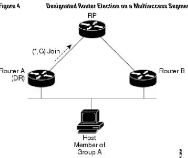
The figure below illustrates what happens on a multiaccess segment. Router A and Router B are connected to a common multiaccess Ethernet segment with Host A as an active receiver for Group A. Only Router A, operating as the DR, sends joins to the RP to construct the shared tree for Group A. If Router B was also permitted to send (*, G) joins to the RP, parallel paths would be created and Host A would receive duplicate multicast traffic. Once Host A begins to source multicast traffic to the group, the DR’s
responsibility is to send register messages to the RP. If both routers were assigned the responsibility, the RP would receive duplicate multicast packets.
Figure 4 Designated Router Election on a Multiaccess Segment
Protocol Independent Multicast Designated Router
If the DR should fail, the PIM-SM provides a way to detect the failure of Router A and elect a failover DR. If the DR (Router A) became inoperable, Router B would detect this situation when its neighbor adjacency with Router A timed out. Because Router B has been hearing MLD membership reports from Host A, it already has MLD state for Group A on this interface and would immediately send a join to the RP when it became the new DR. This step reestablishes traffic flow down a new branch of the shared tree via Router B. Additionally, if Host A were sourcing traffic, Router B would initiate a new register process immediately after receiving the next multicast packet from Host A. This action would trigger the RP to join the SPT to Host A via a new branch through Router B.
Tip Two PIM routers are neighbors if there is a direct connection between them. To display your PIM neighbors, use the show ipv6 pim neighbor command in privileged EXEC mode.
Note The DR election process is required only on multiaccess LANs.
Rendezvous Point
IPv6 PIM provides embedded RP support. Embedded RP support allows the router to learn RP information using the multicast group destination address instead of the statically configured RP. For routers that are the RP, the router must be statically configured as the RP.
The router searches for embedded RP group addresses in MLD reports or PIM messages and data packets. On finding such an address, the router learns the RP for the group from the address itself. It then uses this learned RP for all protocol activity for the group. For routers that are the RP, the router is advertised as an embedded RP must be configured as the RP.
To select a static RP over an embedded RP, the specific embedded RP group range or mask must be configured in the access list of the static RP. When PIM is configured in sparse mode, you must also choose one or more routers to operate as an RP. An RP is a single common root placed at a chosen point of a shared distribution tree and is configured statically in each box.
PIM DRs forward data from directly connected multicast sources to the RP for distribution down the shared tree. Data is forwarded to the RP in one of two ways:
• Data is encapsulated in register packets and unicast directly to the RP by the first-hop router operating as the DR.
• If the RP has itself joined the source tree, it is multicast-forwarded per the RPF forwarding algorithm described in the PIM-Sparse Mode section.
The RP address is used by first-hop routers to send PIM register messages on behalf of a host sending a packet to the group. The RP address is also used by last-hop routers to send PIM join and prune messages to the RP to inform it about group membership. You must configure the RP address on all routers (including the RP router).
A PIM router can be an RP for more than one group. Only one RP address can be used at a time within a PIM domain for a certain group. The conditions specified by the access list determine for which groups the router is an RP.
IPv6 multicast supports the PIM accept register feature, which is the ability to perform PIM-SM register message filtering at the RP. The user can match an access list or compare the AS path for the registered source with the AS path specified in a route map.
Protocol Independent Multicast
PIMv6 Anycast RP Solution Overview
The anycast RP solution in IPv6 PIM allows an IPv6 network to support anycast services for the PIM-SM RP. It allows anycast RP to be used inside a domain that runs PIM only. Anycast RP can be used in IPv4 as well as IPv6, but it does not depend on the Multicast Source Discovery Protocol (MSDP), which runs only on IPv4. This feature is useful when interdomain connection is not required.
Anycast RP is a mechanism that ISP-based backbones use to get fast convergence when a PIM RP device fails. To allow receivers and sources to rendezvous to the closest RP, the packets from a source need to get to all RPs to find joined receivers.
A unicast IP address is chosen as the RP address. This address is either statically configured or distributed using a dynamic protocol to all PIM devices throughout the domain. A set of devices in the domain is chosen to act as RPs for this RP address; these devices are called the anycast RP set. Each device in the anycast RP set is configured with a loopback interface using the RP address. Each device in the anycast RP set also needs a separate physical IP address to be used for communication between the RPs.
The RP address, or a prefix that covers the RP address, is injected into the unicast routing system inside of the domain. Each device in the anycast RP set is configured with the addresses of all other devices in the anycast RP set, and this configuration must be consistent in all RPs in the set.
IPv6 BSR: Configure RP Mapping
PIM routers in a domain must be able to map each multicast group to the correct RP address. The BSR protocol for PIM-SM provides a dynamic, adaptive mechanism to distribute group-to-RP mapping
information rapidly throughout a domain. With the IPv6 BSR feature, if an RP becomes unreachable, it will be detected and the mapping tables will be modified so that the unreachable RP is no longer used, and the new tables will be rapidly distributed throughout the domain.
Every PIM-SM multicast group needs to be associated with the IP or IPv6 address of an RP. When a new multicast sender starts sending, its local DR will encapsulate these data packets in a PIM register message and send them to the RP for that multicast group. When a new multicast receiver joins, its local DR will send a PIM join message to the RP for that multicast group. When any PIM router sends a (*, G) join message, the PIM router needs to know which is the next router toward the RP so that G (Group) can send a message to that router. Also, when a PIM router is forwarding data packets using (*, G) state, the PIM router needs to know which is the correct incoming interface for packets destined for G, because it needs to reject any packets that arrive on other interfaces.
A small set of routers from a domain are configured as candidate bootstrap routers (C-BSRs) and a single BSR is selected for that domain. A set of routers within a domain are also configured as candidate RPs (C-RPs); typically, these routers are the same routers that are configured as C-BSRs. Candidate RPs
periodically unicast candidate-RP-advertisement (C-RP-Adv) messages to the BSR of that domain, advertising their willingness to be an RP. A RP-Adv message includes the address of the advertising C-RP, and an optional list of group addresses and mask length fields, indicating the group prefixes for which the candidacy is advertised. The BSR then includes a set of these C-RPs, along with their corresponding group prefixes, in bootstrap messages (BSMs) it periodically originates. BSMs are distributed hop-by-hop throughout the domain.
Bidirectional BSR support allows bidirectional RPs to be advertised in C-RP messages and bidirectional ranges in the BSM. All routers in a system must be able to use the bidirectional range in the BSM; otherwise, the bidirectional RP feature will not function.
PIM-Source Specific Multicast
PIM-SSM is the routing protocol that supports the implementation of SSM and is derived from PIM-SM. However, unlike PIM-SM where data from all multicast sources are sent when there is a PIM join, the SSM
Protocol Independent Multicast PIMv6 Anycast RP Solution Overview
feature forwards datagram traffic to receivers from only those multicast sources that the receivers have explicitly joined, thus optimizing bandwidth utilization and denying unwanted Internet broadcast traffic. Further, instead of the use of RP and shared trees, SSM uses information found on source addresses for a multicast group. This information is provided by receivers through the source addresses relayed to the last-hop routers by MLD membership reports, resulting in shortest-path trees directly to the sources.
In SSM, delivery of datagrams is based on (S, G) channels. Traffic for one (S, G) channel consists of datagrams with an IPv6 unicast source address S and the multicast group address G as the IPv6 destination address. Systems will receive this traffic by becoming members of the (S, G) channel. Signaling is not required, but receivers must subscribe or unsubscribe to (S, G) channels to receive or not receive traffic from specific sources.
MLD version 2 is required for SSM to operate. MLD allows the host to provide source information. Before SSM will run with MLD, SSM must be supported in the Cisco IPv6 router, the host where the application is running, and the application itself.
• SSM Mapping for IPv6, page 13
• PIM Shared Tree and Source Tree (Shortest-Path Tree), page 13
• Reverse Path Forwarding, page 15
SSM Mapping for IPv6
SSM mapping for IPv6 supports both static and dynamic Domain Name System (DNS) mapping for MLD version 1 receivers. This feature allows deployment of IPv6 SSM with hosts that are incapable of providing MLD version 2 support in their TCP/IP host stack and their IP multicast receiving application.
SSM mapping allows the router to look up the source of a multicast MLD version 1 report either in the running configuration of the router or from a DNS server. The router can then initiate an (S, G) join toward the source.
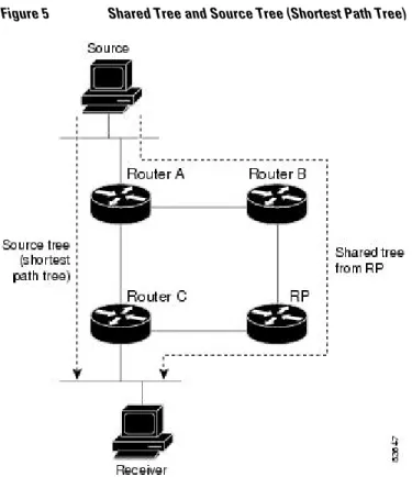
PIM Shared Tree and Source Tree (Shortest-Path Tree)
By default, members of a group receive data from senders to the group across a single data distribution tree rooted at the RP. This type of distribution tree is called shared tree or rendezvous point tree (RPT), as
Protocol Independent Multicast
illustrated in the figure below. Data from senders is delivered to the RP for distribution to group members joined to the shared tree.
Figure 5 Shared Tree and Source Tree (Shortest Path Tree)
If the data threshold warrants, leaf routers on the shared tree may initiate a switch to the data distribution tree rooted at the source. This type of distribution tree is called a shortest path tree or source tree. By default, the Cisco IOS software switches to a source tree upon receiving the first data packet from a source. The following process details the move from shared tree to source tree:
1 Receiver joins a group; leaf Router C sends a join message toward the RP. 2 RP puts the link to Router C in its outgoing interface list.
3 Source sends the data; Router A encapsulates the data in the register and sends it to the RP.
4 RP forwards the data down the shared tree to Router C and sends a join message toward the source. At this point, data may arrive twice at Router C, once encapsulated and once natively.
5 When data arrives natively (unencapsulated) at the RP, the RP sends a register-stop message to Router A.
6 By default, receipt of the first data packet prompts Router C to send a join message toward the source. 7 When Router C receives data on (S, G), it sends a prune message for the source up the shared tree. 8 RP deletes the link to Router C from the outgoing interface of (S, G).
9 RP triggers a prune message toward the source.
Join and prune messages are sent for sources and RPs. They are sent hop-by-hop and are processed by each PIM router along the path to the source or RP. Register and register-stop messages are not sent hop-by-hop. They are sent by the designated router that is directly connected to a source and are received by the RP for the group.
Protocol Independent Multicast PIM Shared Tree and Source Tree (Shortest-Path Tree)
Reverse Path Forwarding
Reverse-path forwarding is used for forwarding multicast datagrams. It functions as follows:
• If a router receives a datagram on an interface it uses to send unicast packets to the source, the packet has arrived on the RPF interface.
• If the packet arrives on the RPF interface, a router forwards the packet out the interfaces present in the outgoing interface list of a multicast routing table entry.
• If the packet does not arrive on the RPF interface, the packet is silently discarded to prevent loops. PIM uses both source trees and RP-rooted shared trees to forward datagrams; the RPF check is performed differently for each, as follows:
• If a PIM router has source-tree state (that is, an (S, G) entry is present in the multicast routing table), the router performs the RPF check against the IPv6 address of the source of the multicast packet. • If a PIM router has shared-tree state (and no explicit source-tree state), it performs the RPF check on
the RP’s address (which is known when members join the group).
Sparse-mode PIM uses the RPF lookup function to determine where it needs to send joins and prunes. (S, G) joins (which are source-tree states) are sent toward the source. (*, G) joins (which are shared-tree states) are sent toward the RP.
Routable Address Hello Option
When an IPv6 interior gateway protocol is used to build the unicast routing table, the procedure to detect the upstream router address assumes the address of a PIM neighbor is always same as the address of the next-hop router, as long as they refer to the same router. However, it may not be the case when a router has multiple addresses on a link.
Two typical situations can lead to this situation for IPv6. The first situation can occur when the unicast routing table is not built by an IPv6 interior gateway protocol such as multicast BGP. The second situation occurs when the address of an RP shares a subnet prefix with downstream routers (note that the RP router address has to be domain-wide and therefore cannot be a link-local address).
The routable address hello option allows the PIM protocol to avoid such situations by adding a PIM hello message option that includes all the addresses on the interface on which the PIM hello message is advertised. When a PIM router finds an upstream router for some address, the result of RPF calculation is compared with the addresses in this option, in addition to the PIM neighbor’s address itself. Because this option includes all the possible addresses of a PIM router on that link, it always includes the RPF calculation result if it refers to the PIM router supporting this option.
Because of size restrictions on PIM messages and the requirement that a routable address hello option fits within a single PIM hello message, a limit of 16 addresses can be configured on the interface.
Bidirectional PIM
Bidirectional PIM allows multicast routers to keep reduced state information, as compared with
unidirectional shared trees in PIM-SM. Bidirectional shared trees convey data from sources to the RPA and distribute them from the RPA to the receivers. Unlike PIM-SM, bidirectional PIM does not switch over to the source tree, and there is no register encapsulation of data from the source to the RP.
A single designated forwarder (DF) exists for each RPA on every link within a bidirectional PIM domain (including multiaccess and point-to-point links). The only exception is the RPL on which no DF exists. The DF is the router on the link with the best route to the RPA, which is determined by comparing MRIB-provided metrics. A DF for a given RPA forwards downstream traffic onto its link and forwards upstream
Protocol Independent Multicast
traffic from its link toward the rendezvous point link (RPL). The DF performs this function for all bidirectional groups that map to the RPA. The DF on a link is also responsible for processing Join messages from downstream routers on the link as well as ensuring that packets are forwarded to local receivers discovered through a local membership mechanism such as MLD.
Bidirectional PIM offers advantages when there are many moderate or low-rate sources. However, the bidirectional shared trees may have worse delay characteristics than do the source trees built in PIM-SM (depending on the topology).
Only static configuration of bidirectional RPs is supported in IPv6.
Static Mroutes
IPv6 static mroutes behave much in the same way as IPv4 static mroutes used to influence the RPF check. IPv6 static mroutes share the same database as IPv6 static routes and are implemented by extending static route support for RPF checks. Static mroutes support equal-cost multipath mroutes, and they also support unicast-only static routes.
MRIB
The Multicast Routing Information Base (MRIB) is a protocol-independent repository of multicast routing entries instantiated by multicast routing protocols (routing clients). Its main function is to provide
independence between routing protocols and the Multicast Forwarding Information Base (MFIB). It also acts as a coordination and communication point among its clients.
Routing clients use the services provided by the MRIB to instantiate routing entries and retrieve changes made to routing entries by other clients. Besides routing clients, MRIB also has forwarding clients (MFIB instances) and special clients such as MLD. MFIB retrieves its forwarding entries from MRIB and notifies the MRIB of any events related to packet reception. These notifications can either be explicitly requested by routing clients or spontaneously generated by the MFIB.
Another important function of the MRIB is to allow for the coordination of multiple routing clients in establishing multicast connectivity within the same multicast session. MRIB also allows for the coordination between MLD and routing protocols.
MFIB
The MFIB is a platform-independent and routing-protocol-independent library for IPv6 software. Its main purpose is to provide a Cisco platform with an interface with which to read the IPv6 multicast forwarding table and notifications when the forwarding table changes. The information provided by the MFIB has clearly defined forwarding semantics and is designed to make it easy for the platform to translate to its specific hardware or software forwarding mechanisms.
When routing or topology changes occur in the network, the IPv6 routing table is updated, and those changes are reflected in the MFIB. The MFIB maintains next-hop address information based on the information in the IPv6 routing table. Because there is a one-to-one correlation between MFIB entries and routing table entries, the MFIB contains all known routes and eliminates the need for route cache
maintenance that is associated with switching paths such as fast switching and optimum switching. • Distributed MFIB, page 16
Distributed MFIB
Distributed Multicast Forwarding Information Base (MFIB) is used to switch multicast IPv6 packets on distributed platforms. Distributed MFIB may also contain platform-specific information on replication
Static Mroutes Distributed MFIB
across line cards. The basic MFIB routines that implement the core of the forwarding logic are common to all forwarding environments.
dMFIB implements the following functions:
• Distributes a copy of the MFIB to the line cards.
• Relays data-driven protocol events generated in the line cards to PIM.
• Provides an MFIB platform application program interface (API) to propagate MFIB changes to platform-specific code responsible for programming the hardware acceleration engine. This API also includes entry points to switch a packet in software (necessary if the packet is triggering a data-driven event) and to upload traffic statistics to the software.
• Provides hooks to allow clients residing on the RP to read traffic statistics on demand. Distributed MFIB does not periodically upload these statistics to the RP.
The combination of distributed MFIB and MRIB subsystems allows the device to have a "customized" copy of the MFIB database in each line card and to transport MFIB-related platform-specific information from the RP to the line cards.
IPv6 Multicast VRF Lite
The IPv6 Multicast VRF Lite feature provides IPv6 multicast support for multiple virtual routing/ forwarding contexts (VRFs). The scope of these VRFs is limited to the router in which the VRFs are defined.
This feature provides separation between routing and forwarding, providing an additional level of security because no communication between devices belonging to different VRFs is allowed unless it is explicitly configured. The IPv6 Multicast VRF Lite feature simplifies the management and troubleshooting of traffic belonging to a specific VRF.
IPv6 Multicast Process Switching and Fast Switching
A unified MFIB is used to provide both fast switching and process switching support for PIM-SM and PIM-SSM in IPv6 multicast. In process switching, the Route Processor must examine, rewrite, and forward each packet. The packet is first received and copied into the system memory. The router then looks up the Layer 3 network address in the routing table. The Layer 2 frame is then rewritten with the next-hop destination address and sent to the outgoing interface. The RP also computes the cyclic redundancy check (CRC). This switching method is the least scalable method for switching IPv6 packets.
IPv6 multicast fast switching allows routers to provide better packet forwarding performance than process switching. Information conventionally stored in a route cache is stored in several data structures for IPv6 multicast switching. The data structures provide optimized lookup for efficient packet forwarding. In IPv6 multicast forwarding, the first packet is fast-switched if the PIM protocol logic allows it. In IPv6 multicast fast switching, the MAC encapsulation header is precomputed. IPv6 multicast fast switching uses the MFIB to make IPv6 destination prefix-based switching decisions. In addition to the MFIB, IPv6 multicast fast switching uses adjacency tables to prepend Layer 2 addressing information. The adjacency table maintains Layer 2 next-hop addresses for all MFIB entries.
The adjacency table is populated as adjacencies are discovered. Each time an adjacency entry is created (such as through ARP), a link-layer header for that adjacent node is precomputed and stored in the
adjacency table. Once a route is determined, it points to a next hop and corresponding adjacency entry. It is subsequently used for encapsulation during switching of packets.
A route might have several paths to a destination prefix, such as when a router is configured for
simultaneous load balancing and redundancy. For each resolved path, a pointer is added for the adjacency
IPv6 Multicast VRF Lite
corresponding to the next-hop interface for that path. This mechanism is used for load balancing across several paths.
Multiprotocol BGP for the IPv6 Multicast Address Family
The multiprotocol BGP for the IPv6 multicast address family feature provides multicast BGP extensions for IPv6 and supports the same features and functionality as IPv4 BGP. IPv6 enhancements to multicast BGP include support for an IPv6 multicast address family and network layer reachability information (NLRI) and next hop (the next router in the path to the destination) attributes that use IPv6 addresses. Multicast BGP is an enhanced BGP that allows the deployment of interdomain IPv6 multicast.
Multiprotocol BGP carries routing information for multiple network layer protocol address families; for example, IPv6 address family and for IPv6 multicast routes. The IPv6 multicast address family contains routes used for RPF lookup by the IPv6 PIM protocol, and multicast BGP IPv6 provides for interdomain transport of the same. Users must use multiprotocol BGP for IPv6 multicast when using IPv6 multicast with BGP because the unicast BGP learned routes will not be used for IPv6 multicast.
Multicast BGP functionality is provided through a separate address family context. A subsequent address family identifier (SAFI) provides information about the type of the network layer reachability information that is carried in the attribute. Multiprotocol BGP unicast uses SAFI 1 messages, and multiprotocol BGP multicast uses SAFI 2 messages. SAFI 1 messages indicate that the routes are usable only for IP unicast, not IP multicast. Because of this functionality, BGP routes in the IPv6 unicast RIB must be ignored in the IPv6 multicast RPF lookup.
A separate BGP routing table is maintained to configure incongruent policies and topologies (for example, IPv6 unicast and multicast) by using IPv6 multicast RPF lookup. Multicast RPF lookup is very similar to the IP unicast route lookup.
No MRIB is associated with the IPv6 multicast BGP table. However, IPv6 multicast BGP operates on the unicast IPv6 RIB when needed. Multicast BGP does not insert or update routes into the IPv6 unicast RIB.
NSF and SSO Support In IPv6 Multicast
Support for nonstop forwarding (NSF) and stateful switchover (SSO) is provided in IPv6 Multicast.
Bandwidth-Based CAC for IPv6 Multicast
The bandwidth-based call admission control (CAC) for IPv6 multicast feature implements a way to count per-interface mroute state limiters using cost multipliers. This feature can be used to provide bandwidth-based CAC on a per-interface basis in network environments where the multicast flows use different amounts of bandwidth.
This feature limits and accounts for IPv6 multicast state in detail. When this feature is configured,
interfaces can be limited to the number of times they may be used as incoming or outgoing interfaces in the IPv6 multicast PIM topology.
With this feature, router administrators can configure global limit cost commands for state matching access lists and specify which cost multiplier to use when accounting such state against the interface limits. This feature provides the required flexibility to implement bandwidth-based local CAC policy by tuning appropriate cost multipliers for different bandwidth requirements.
How to Implement IPv6 Multicast
Multiprotocol BGP for the IPv6 Multicast Address Family How to Implement IPv6 Multicast
• Enabling IPv6 Multicast Routing, page 19
• Customizing and Verifying the MLD Protocol, page 19
• Configuring PIM, page 31
• Configuring a BSR, page 39
• Configuring SSM Mapping, page 44
• Configuring Static Mroutes, page 46
• Configuring IPv6 Multiprotocol BGP, page 47
• Configuring Bandwidth-Based CAC for IPv6, page 57
• Using MFIB in IPv6 Multicast, page 60
• Disabling Default Features in IPv6 Multicast, page 63
Enabling IPv6 Multicast Routing
SUMMARY STEPS1. enable
2. configure terminal
3. ipv6 multicast-routing [vrf vrf-name]
DETAILED STEPS
Command or Action Purpose Step 1 enable
Example:
Router> enable
Enables privileged EXEC mode. • Enter your password if prompted.
Step 2 configure terminal
Example:
Router# configure terminal
Enters global configuration mode.
Step 3 ipv6 multicast-routing [vrf vrf-name]
Example:
Router(config)# ipv6 multicast-routing
Enables multicast routing on all IPv6-enabled interfaces and enables multicast forwarding for PIM and MLD on all enabled interfaces of the router.
Customizing and Verifying the MLD Protocol
• Customizing and Verifying MLD on an Interface, page 20
• Implementing MLD Group Limits, page 22
• Configuring Explicit Tracking of Receivers to Track Host Behavior, page 24
Enabling IPv6 Multicast Routing
• Configuring Multicast User Authentication and Profile Support, page 25
• Enabling MLD Proxy in IPv6, page 28
• Resetting the MLD Traffic Counters, page 30
• Clearing the MLD Interface Counters, page 31
Customizing and Verifying MLD on an Interface
SUMMARY STEPS 1. enable
2. configure terminal
3. interface type number
4. ipv6 mld join-group [group-address] [include | exclude] {source-address | source-list [acl]}
5. ipv6 mld access-group access-list-name
6. ipv6 mld static-group group-address ] [include| exclude] {source-address | source-list [acl]}
7. ipv6 mld query-max-response-time seconds
8. ipv6 mld query-timeout seconds
9. ipv6 mld query-interval seconds
10.exit
11.show ipv6 mld [vrf vrf-name] groups [link-local] [group-name | group-address] [interface-type interface-number] [detail | explicit]
12.show ipv6 mld groups summary
13.show ipv6 mld [vrf vrf-name] interface [type number]
14.debug ipv6 mld [group-name | group-address | interface-type]
15.debug ipv6 mld explicit [group-name | group-address
DETAILED STEPS
Command or Action Purpose
Step 1 enable
Example:
Router> enable
Enables privileged EXEC mode. • Enter your password if prompted.
Step 2 configure terminal
Example:
Router# configure terminal
Enters global configuration mode.
Customizing and Verifying the MLD Protocol Customizing and Verifying MLD on an Interface
Command or Action Purpose Step 3 interface type number
Example:
Router(config)# interface FastEthernet 1/0
Specifies an interface type and number, and places the router in interface configuration mode.
Step 4 ipv6 mld join-group [group-address] [include | exclude] {source-address | source-list [acl]}
Example:
Router(config-if)# ipv6 mld join-group FF04::10
Configures MLD reporting for a specified group and source.
Step 5 ipv6 mld access-group access-list-name
Example:
Router(config-if)# ipv6 access-list acc-grp-1
Allows the user to perform IPv6 multicast receiver access control.
Step 6 ipv6 mld static-group group-address ] [include| exclude] {source-address | source-list [acl]}
Example:
Router(config-if)# ipv6 mld static-group ff04::10 include 100::1
Statically forwards traffic for the multicast group onto a specified interface and cause the interface to behave as if a MLD joiner were present on the interface.
Step 7 ipv6 mld query-max-response-time seconds
Example:
Router(config-if)# ipv6 mld query-max-response-time 20
Configures the maximum response time advertised in MLD queries.
Step 8 ipv6 mld query-timeout seconds
Example:
Router(config-if)# ipv6 mld query-timeout 130
Configures the timeout value before the router takes over as the querier for the interface.
Step 9 ipv6 mld query-interval seconds
Example:
Router(config-if)# ipv6 mld query-interval 60
Configures the frequency at which the Cisco IOS software sends MLD host-query messages. Caution Changing this value may severely impact
multicast forwarding.
Customizing and Verifying the MLD Protocol
Command or Action Purpose Step 10 exit
Example:
Router(config-if)# exit
Enter this command twice to exit interface
configuration mode and enter privileged EXEC mode.
Step 11 show ipv6 mld [vrf vrf-name] groups [link-local] [group-name | group-address] [interface-type interface-number] [detail | explicit]
Example:
Router# show ipv6 mld groups FastEthernet 2/1
Displays the multicast groups that are directly connected to the router and that were learned through MLD.
Step 12 show ipv6 mld groups summary
Example:
Router# show ipv6 mld groups summary
Displays the number of (*, G) and (S, G) membership reports present in the MLD cache.
Step 13 show ipv6 mld [vrf vrf-name] interface [type number]
Example:
Router# show ipv6 mld interface FastEthernet 2/1
Displays multicast-related information about an interface.
Step 14 debug ipv6 mld [group-name | group-address | interface-type] Example:
Router# debug ipv6 mld
Enables debugging on MLD protocol activity.
Step 15 debug ipv6 mld explicit [group-name | group-address
Example:
Router# debug ipv6 mld explicit
Displays information related to the explicit tracking of hosts.
Implementing MLD Group Limits
Per-interface and global MLD limits operate independently of each other. Both per-interface and global MLD limits can be configured on the same router. The number of MLD limits, globally or per interface, is not configured by default; the limits must be configured by the user. A membership report that exceeds either the per-interface or the global state limit is ignored.
• Implementing MLD Group Limits Globally, page 23
Customizing and Verifying the MLD Protocol Implementing MLD Group Limits
• Implementing MLD Group Limits per Interface, page 23
Implementing MLD Group Limits Globally SUMMARY STEPS
1. enable
2. configure terminal
3. ipv6 mld [vrf vrf-name] state-limit number
DETAILED STEPS
Command or Action Purpose
Step 1 enable
Example:
Router> enable
Enables privileged EXEC mode. • Enter your password if prompted.
Step 2 configure terminal
Example:
Router# configure terminal
Enters global configuration mode.
Step 3 ipv6 mld [vrf vrf-name] state-limit number
Example:
Router(config)# ipv6 mld state-limit 300
Limits the number of MLD states globally.
Implementing MLD Group Limits per Interface SUMMARY STEPS
1. enable
2. configure terminal
3. interface type number
4. ipv6 mld limit number [except access-list
Customizing and Verifying the MLD Protocol
DETAILED STEPS
Command or Action Purpose
Step 1 enable
Example:
Router> enable
Enables privileged EXEC mode. • Enter your password if prompted.
Step 2 configure terminal
Example:
Router# configure terminal
Enters global configuration mode.
Step 3 interface type number
Example:
Router(config)# interface FastEthernet 1/0
Specifies an interface type and number, and places the router in interface configuration mode.
Step 4 ipv6 mld limit number [except access-list
Example:
Router(config-if)# ipv6 mld limit 100
Limits the number of MLD states on a per-interface basis.
Configuring Explicit Tracking of Receivers to Track Host Behavior
The explicit tracking feature allows a router to track the behavior of the hosts within its IPv6 network and enables the fast leave mechanism to be used with MLD version 2 host reports.
SUMMARY STEPS 1. enable
2. configure terminal
3. interface type number
4. ipv6 mld explicit-tracking access-list-name
Customizing and Verifying the MLD Protocol Configuring Explicit Tracking of Receivers to Track Host Behavior
DETAILED STEPS
Command or Action Purpose
Step 1 enable
Example:
Router> enable
Enables privileged EXEC mode. • Enter your password if prompted.
Step 2 configure terminal
Example:
Router# configure terminal
Enters global configuration mode.
Step 3 interface type number
Example:
Router(config)# interface FastEthernet 1/0
Specifies an interface type and number, and places the router in interface configuration mode.
Step 4 ipv6 mld explicit-tracking access-list-name
Example:
Router(config-if)# ipv6 mld explicit-tracking list1
Enables explicit tracking of hosts.
Configuring Multicast User Authentication and Profile Support
• Prerequisites, page 25
• Restrictions, page 25
• Enabling AAA Access Control for IPv6 Multicast, page 26
• Specifying Method Lists and Enabling Multicast Accounting, page 26
• Disabling the Router from Receiving Unauthenticated Multicast Traffic, page 27
Prerequisites
Before you configure multicast user authentication and profile support, you may configure the following receiver access control functions in IPv6 multicast.
Restrictions
Before you configure multicast user authentication and profile support, you should be aware of the following restrictions:
• The port, interface, VC, or VLAN ID is the user or subscriber identity. User identity by hostname, user ID, or password is not supported.
• Enabling AAA Access Control for IPv6 Multicast, page 26
Customizing and Verifying the MLD Protocol
• Specifying Method Lists and Enabling Multicast Accounting, page 26
• Disabling the Router from Receiving Unauthenticated Multicast Traffic, page 27
• Resetting Authorization Status on an MLD Interface, page 29
Enabling AAA Access Control for IPv6 Multicast SUMMARY STEPS
1. enable
2. configure terminal
3. aaa new-model
DETAILED STEPS
Command or Action Purpose
Step 1 enable
Example:
Router> enable
Enables privileged EXEC mode. • Enter your password if prompted.
Step 2 configure terminal
Example:
Router# configure terminal
Enters global configuration mode.
Step 3 aaa new-model
Example:
Router(config)# aaa new-model
Enables the AAA access control system.
Specifying Method Lists and Enabling Multicast Accounting
Perform this task to specify the method lists used for AAA authorization and accounting and how to enable multicast accounting on specified groups or channels on an interface.
SUMMARY STEPS 1. enable
2. configure terminal
3. aaa authorization multicast default [method3 | method4
4. aaa accounting multicast default [start-stop | stop-only] [broadcast] [method1] [method2] [method3] [method4
5. interface type number
6. ipv6 multicast aaa account receive access-list-name [throttle throttle-number
Customizing and Verifying the MLD Protocol Enabling AAA Access Control for IPv6 Multicast
DETAILED STEPS
Command or Action Purpose
Step 1 enable
Example:
Router> enable
Enables privileged EXEC mode. • Enter your password if prompted.
Step 2 configure terminal
Example:
Router# configure terminal
Enters global configuration mode.
Step 3 aaa authorization multicast default [method3 | method4
Example:
Router(config)# aaa authorization multicast default
Enables AAA authorization and sets parameters that restrict user access to an IPv6 multicast network.
Step 4 aaa accounting multicast default [start-stop | stop-only] [broadcast] [method1] [method2] [method3] [method4
Example:
Router(config)# aaa accounting multicast default
Enables AAA accounting of IPv6 multicast services for billing or security purposes when you use RADIUS.
Step 5 interface type number
Example:
Router(config)# interface FastEthernet 1/0
Specifies an interface type and number, and places the router in interface configuration mode.
Step 6 ipv6 multicast aaa account receive access-list-name [throttle throttle-number
Example:
Router(config-if)# ipv6 multicast aaa account receive list1
Enables AAA accounting on specified groups or channels.
Disabling the Router from Receiving Unauthenticated Multicast Traffic
In some situations, access control may be needed to prevent multicast traffic from being received unless the subscriber is authenticated and the channels are authorized as per access control profiles. That is, there should be no traffic at all unless specified otherwise by access control profiles.
Customizing and Verifying the MLD Protocol
Perform this task to disable the router from receiving multicast traffic to be received from unauthenticated groups or unauthorized channels.
SUMMARY STEPS 1. enable
2. configure terminal
3. ipv6 multicast [vrf vrf-name] group-range[access-list-name]
DETAILED STEPS
Command or Action Purpose
Step 1 enable
Example:
Router> enable
Enables privileged EXEC mode. • Enter your password if prompted.
Step 2 configure terminal
Example:
Router# configure terminal
Enters global configuration mode.
Step 3 ipv6 multicast [vrf vrf-name] group-range[access-list-name]
Example:
Router(config)# ipv6 multicast group-range
Disables multicast protocol actions and traffic forwarding for unauthorized groups or channels on all the interfaces in a router.
Enabling MLD Proxy in IPv6
SUMMARY STEPS 1. enable
2. configure terminal
3. ipv6 mld host-proxy [group-acl
4. ipv6 mld host-proxy interface [group-acl]
5. show ipv6 mld host-proxy [interface-type interface-number] group [group-address]]
Customizing and Verifying the MLD Protocol Enabling MLD Proxy in IPv6
DETAILED STEPS
Command or Action Purpose
Step 1 enable
Example:
Router> enable
Enables privileged EXEC mode. • Enter your password if prompted.
Step 2 configure terminal
Example:
Router# configure terminal
Enters global configuration mode.
Step 3 ipv6 mld host-proxy [group-acl
Example:
Router(config)# ipv6 mld host-proxy proxy-group
Enables the MLD proxy feature.
Step 4 ipv6 mld host-proxy interface [group-acl]
Example:
Router(config)# ipv6 mld host-proxy interface Ethernet 0/0
Enables the MLD proxy feature on a specified interface on an RP.
Step 5 show ipv6 mld host-proxy [interface-type interface-number] group [group-address]]
Example:
Router# show ipv6 mld host-proxy Ethernet0/0
Displays IPv6 MLD host proxy information.
• Resetting Authorization Status on an MLD Interface, page 29
Resetting Authorization Status on an MLD Interface
If no interface is specified, authorization is reset on all MLD interfaces.
SUMMARY STEPS 1. enable
2. clear ipv6 multicast aaa authorization [interface-type interface-number
Customizing and Verifying the MLD Protocol