DCREG INTERFACE
VIA DEVICENET
Update 27/09/06 R.00 Version D4.02
• This manual is an integral and essential part of the product. Carefully read the instructions contained herein as they provide important hints for use and maintenance safety.
• This product shall be used only for the purposes it is aimed at. Any other use is to be considered as improper and dangerous. The manufacturer is not responsible for any possible damage caused by improper, erroneous and irrational applications.
• Elettronica Santerno reserve the right to make any technical changes to this manual without prior notice. Any misprint or spelling mistake will be edited in the new versions of this manual.
• Elettronica Santerno is responsible for the information contained in the original version of the Italian manual.
• The information contained herein is Elettronica Santerno’s property and cannot be reproduced. Elettronica Santerno enforces its rights on the drawings and catalogues according to the law.
INDEX
INDEX...2
1.1 EDS File ...3
2 DEVICENET FIELDBUS COMMUNICATIONS BOARD ...4
2.1 Main Features ...4
2.2 Devicenet Fieldbus Terminals ...5
2.3 Board Configuration...5
2.4 Connection to the Fieldbus ...6
2.5 Indications ...8
2.5.1 Front LEDs ...8
2.5.2 LED on the Control Board...8
3 PARAMETER EXCHANGE...9
3.1 From Master to DCREG ...9
3.2 From DCREG to Master ...9
1 COMMUNICATION FEATURES
This manual describes how to interface a DCREG (slave) converter with an intelligent outside control unit (master) via Devicenet.
In order to create this interface, an optional module must be installed on the DCREG (see Module description).
The converter thus becomes a slave node from which a Devicenet master can read and on which it can write. The DCREG will never start a communication towards other nodes, but will only answer incoming commands.
Via Devicenet you can:
• read the parameters mentioned in the following From Master to DCREG
• write the parameters mentioned in the following From DCREG to Master
1.1 EDS File
Each device in a Devicenet network is associated with an Electronic Data Sheet (EDS), containing all the information needed about the device. This file is used by the network configuration program during configuration of the network.
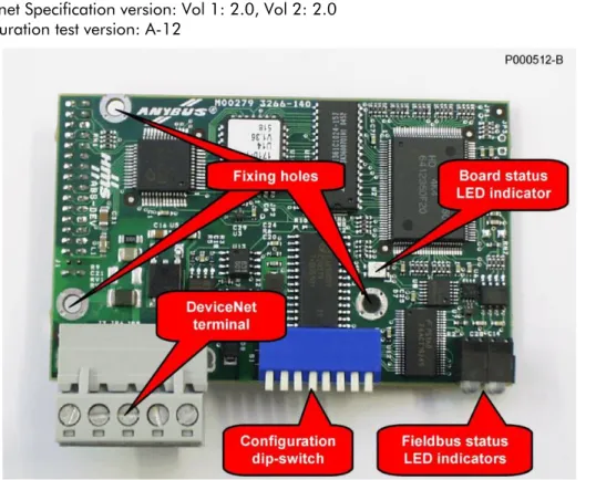
2 DEVICENET FIELDBUS COMMUNICATIONS BOARD
The Devicenet communications board allows to interface a DCREG with an external control unit through a communications interface using a CAN protocol of the Devicenet 2.0 type. The baud rate and the MAC ID can be set through the on-board dip-switches.
Max. 512 bytes for input/output data are available; some of them are used for the interfacing with the DCREG.
2.1 Main Features
- Baud Rate: 125, 250, 500 kbits/s
- DIP switch for baud rate and MAC ID selection
- Optically isolated Devicenet interface
- Max. 512 bytes for input & output data
- Max. 2048 bytes for input & output data through mailbox
- Devicenet Specification version: Vol 1: 2.0, Vol 2: 2.0
- Configuration test version: A-12
2.2 Devicenet Fieldbus Terminals
The Devicenet Fieldbus communications board is provided with a removable, screwable terminal board (pitch 5.08). The bus interface circuitry has an external supply of 24VDC ±10%, as prescribed from the CAN Devicenet specifications.
Terminal arrangement as stated in the table: N. Name Description
1 V- Negative voltage for bus supply 2 CAN_L CAN_L bus line
3 SHIELD Cable shielding 4 CAN_H CAN_H bus line 5 V+ Positive voltage for bus supply
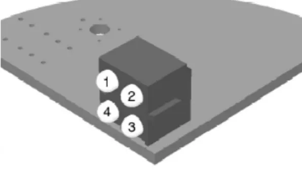
2.3 Board Configuration
The on-board dip-switches allow to set the baud rate and the MAC ID identifying the device in the Devicenet network.
Dip-switches 1 and 2 allow to set the baud rate, that must be the same for all the related devices. The Devicenet standard allows three baud rates: 125, 250 and 500 kbits/s. Possible settings are the following:
Baudrate Setting of sw.1 & sw.2 125 kbits/s sw.1=OFF sw.2=OFF 250 kbits/s sw.1=OFF sw.2=ON 500 kbits/s sw.1=ON sw.2=OFF
The MAC ID can be set between 0 and 63 by entering the configuration of the binary number for six dip-switches, from sw.3 to sw.8. The most significant bit (MSB) is set through sw.3, while the least significant bit (LSB) is set through sw.8.
Some possible settings are shown in the table below:
MAC ID sw.3 (MSB) sw.4 sw.5 sw.6 sw.7 sw.8 (LSB) 0 OFF OFF OFF OFF OFF OFF 1 OFF OFF OFF OFF OFF ON 2 OFF OFF OFF OFF ON OFF 3 OFF OFF OFF OFF ON ON ….. ….. ….. ….. ….. ….. …..
62 ON ON ON ON ON OFF 63 ON ON ON ON ON ON
2.4 Connection to the Fieldbus
The wiring quality is fundamental for the best reliability of the bus operation. The higher the baud rates, the shortest the bus lengths allowed.
Reliability is strongly affected by the type of wiring and the wire topology. The Devicenet standard allows four types of wires based on the type of related devices. It also allows to connect signal dispatching nodes, line terminators and supply couplers. Two types of lines are defined: the trunk line and the drop lines. Figure xx illustrates the topology of a typical Devicenet trunk line.
Figure 2: Outline of the topology of a Devicenet trunk line
The DCREG equipped with a Devicenet interface board is typically connected through a drop line consisting of a 5-conductor shielded cable. The Devicenet standard defines three shielded cables based on their diameter: THICK, MID, and THIN cables. The maximum electric length between two Devicenet devices depends on the baud rate and the type of cable being used.
The table below shows the maximum lengths that are recommended based on these variables. The FLAT cable can be used for the main trunk line if drop lines are connected through a system that does not require welding.
Baud Rate Max. length with FLAT cable Max. length with THICK cable Max. length with MID cable Max. length with THIN cable
125 kbits/s 420m 500m 300m 100m
250 kbits/s 200m 250m 250m 100m
NOTE
Each Devicenet trunk line must meet some geometric requirements and must provide two terminator nodes and at least one supply node, because devices can be totally or partially powered via the bus. The type of the cable being used also determines the max. supply current available for the bus devices.
NOTE
For a more comprehensive overview of the Devicenet standard, go to ODVA’s home page (http://www.odva.org).
In particular, you can refer to the “Planning and Installation Manual - DevicenetTM Cable System” document at
http://www.odva.org/10_2/Cable_Manual/Cable_Guide/Cable_Guide_Print.pdf NOTE In case of failures or disturbance in the Devicenet communications, please fill in the “Devicenet Baseline & Test Report” form in the Appendix C of the “Planning
2.5 Indications
The module is provided with four LEDs installed on its front part and with one LED assembled on the control board which is used for debugging operations.
2.5.1 F
RONTLED
SFigure 3: Indications LEDs
The LED functions are described in the table below:
LED State Description 1.
Reserved Reserved for future use Off Off Not powered / Not online Green, steady Link OK, On line, Connected Green, flashing On line, Not connected Red, steady Critical link failure 2.
Network Status
Red, flashing Connection timeout Off No power to device Green, steady Device operational
Green, flashing Data size bigger than configured Red, steady Unrecoverable fault
3. Module Status
Red, flashing Minor fault 4.
Reserved Reserved for future use
2.5.2 LED
ON THEC
ONTROLB
OARDThe LED located on the control board is a Watchdog LED indicating the state of the module according to the table below:
3 PARAMETER EXCHANGE
The following table shows the parameters of the DCREG exchanged via Devicenet. In each of the following are listed:
1) the number and the name of the parameter, 2) its meaning,
3) its range,
4) its unit of measure (shown on the display),
5) the ratio between the value inside the DCREG (exchanged via Devicenet) and the physical value represented (as shown on the display).
NOTE: unless otherwise specified, each parameter is exchanged as integer with sign at 16 bit (between – 32768 and +32767).
For further information on parameter configuration, refer to the "OPERATION MANUAL 15P0059B3 DCREG2 DCREG4” R.05 Software Vers. D4.01...
3.1 From Master to DCREG
1) Name 2) Meaning 3) Range 4) Unit of measure 5) Ratio M016 FBRref Speed / voltage reference from Devicenet -100 ÷ +100 % 100 / 3FFFh M019 AnOut1 Analog output 1 on terminal 8 -10 ÷ +10 V 10 / FFFh M020 AnOut2 Analog output 2 on terminal 10 -10 ÷ +10 V 10 / FFFh
M022 MDO Digital output state 00000xxxb ÷
11111xxxb Note A) –
P050 Ilim1A First current limit bridge A 0 ÷ 300 % 1 P051 Ilim1B First current limit bridge B 0 ÷ 300 % 1
not used – – – –
M031 FBDigIn Digital input state from Devicenet 00000000b ÷
11111111b Note B) –
3.2 From DCREG to Master
1) Name 2) Meaning 3) Range 4) Unit of measure 5) Ratio
temp – – Note C)
Note A) Bit 3 → MDO5 Bit 4 → MDO1 Bit 5 → MDO2 Bit 6 → MDO3 Bit 7 → MDO4
Note B)
Bit 0 → ENABLE Bit 1 → START Bit 2 → MDI1 Bit 3 → MDI2 Bit 4 → MDI3 Bit 5 → MDI4 Bit 6 → MDI5 Bit 7 → MDI6
Note C)
The two 8-bit variables AlarmNumber and Led are mapped inside the variable temp. Its meaning is the following:
high part low part
Led AlarmNumber AlarmNumber has the following meaning: Drive OK if AlarmNumber = 0;
Alarm = AlarmNumber if AlarmNumber ≤ 33; Warning = AlarmNumber-33 if AlarmNumber > 33.
Led indicates the state of the LEDs on the remotable keyboard with the following map: Bit 0 → RUN
Bit 1 → FORWARD Bit 2 → LOC SEQ Bit 3 → BRAKE Bit 4 → REF Bit 5 → REVERSE Bit 6 → LOC REM Bit 7 → LIMIT
3.3 Alarm A028 Communication Interrupted
This alarm will trip if the DCREG does not receive any valid message via Devicenet within the timeout which can be set using parameter C143 A028Delay. This alarm can be inhibited using parameter C159 A028Inhibit.