Plastics piping systems
for water supply —
Polyethylene (PE) —
Part 3: Fittings
The European Standard EN 12201-3:2003 has the status of a British Standard
This British Standard, was published under the authority of the Standards Policy and Strategy Committee on 5 December 2003
© BSI 5 December 2003
ISBN 0 580 42981 4
National foreword
This British Standard is the official English language version of
EN 12201-3:2003. Collectively, EN 12201-1, EN 12201-2 and EN 12201-5 comprise a revision of:
— BS 6572:1985, Specification for blue polyethylene pipes up to nominal size 63 for below ground use for potable water;
— BS 6730:1986, Specification for black polyethylene pipes up to nominal size 63 for above ground use for cold potable water.
It is intended that these British Standards will be declared obsolescent by March 2005.
NOTE 1 The UK water industry has indicated that following the publication of this British Standard, the following Water Industry Specification will be declared obsolescent by March 2005 and retained for reference where applicable:
— WIS 4-32-14, Specification for PE 80 and PE 100 electrofusion fittings for
nominal sizes up to and including 630 mm1);
— WIS 4-32-15, Specification for PE 80 and PE 100 spigot fittings and drawn
bends for nominal sizes up to and including 1 000 mm1).
The UK participation in its preparation was entrusted by Technical Committee PRI/88 (previously PRI/61), Plastics piping systems, to Subcommittee PRI/88/2 (previously PRI/61/2), Plastics piping systems for pressure applications, which has the responsibility to:
A list of organizations represented on this subcommittee can be obtained on request to its secretary.
NOTE 2 It was decided not to proceed with the publication of prEN 12201-6, Recommended practice for installation, and that existing national practices would be applicable. In the UK, in the absence of a British Standard covering installation, it is the opinion of Technical Committee PRI/88, Plastics piping systems, that reference to the Polyethylene Pipe Systems Manual2), a joint publication of WRc and BPF Plastic Pipes Group represents established UK practice.
NOTE 3 Part 7 has been prepared as a CEN/TS, to allow further development. CEN/TS 12201-7 is not mandatory under the Public Procurement Directive.
1)Published by WRc, Swindon.
— aid enquirers to understand the text;
— present to the responsible international/European committee any enquiries on the interpretation, or proposals for change, and keep the UK interests informed;
— monitor related international and European developments and promulgate them in the UK.
2)WRc/BPF PLASTIC PIPES GROUP. Polyethylene Pipe Systems Manual. Swindon: WRc, 2002.
Amendments issued since publication
Attention is drawn to the following statutory regulations:
Health and Safety at Work etc. Act 1974 and subsequent regulations.
Attention is also drawn to any appropriate safety precautions. It is assumed in the drafting of a standard that the execution of its provisions is entrusted to appropriately qualified people.
Additional information
With reference to the Introduction and 5.6, as yet there is no pan-European agreement on water quality requirements, so existing UK regulations remain in force. Regulation 25 of the Water Supply (Water Quality) Regulations 1989 specifies the circumstances in which water undertakers may use products in contact with water supplies in England and Wales. As part of the UK
regulations, all pipes and fittings used to convey drinking water supplies are required to be approved under the provisions of Regulation 25(1) (a) or (b) as appropriate and the Water Regulation Advisory Scheme (WRAS) to ensure that their use will not cause adverse effect on water quality or a risk to health of consumers. In Scotland and Northern Ireland there are similar provisions. These regulations will be revised as necessary to comply with the EU Drinking Water Quality Directive.
The UK National Annex NA attached to this standard provides additional information on the selection and installation of piping systems and components in the UK.
Cross-references
The British Standards which implement international or European publications referred to in this document may be found in the BSI Catalogue under the section entitled “International Standards Correspondence Index”, or by using the “Search” facility of the BSI Electronic Catalogue or of British Standards Online. This publication does not purport to include all the necessary provisions of a contract. Users are responsible for its correct application.
Compliance with a British Standard does not of itself confer immunity from legal obligations.
Summary of pages
This document comprises a front cover, an inside front cover, pages i and ii, the EN title page, pages 2 to 26, an inside back cover and a back cover.
The BSI copyright notice displayed in this document indicates when the document was last issued.
NORME EUROPÉENNE
EUROPÄISCHE NORM
March 2003ICS 23.040.45; 91.140.60
English version
Plastics piping systems for water supply Polyethylene (PE)
-Part 3: Fittings
Systèmes de canalisations en plastique pour l'alimentation en eau - Polyéthylène (PE) - Partie 3: Aptitude à l'emploi
Kunststoff-Rohrleitungssysteme für die Wasserversorgung - Polyethylen (PE) - Teil 3: Formstücke
This European Standard was approved by CEN on 4 December 2002.
CEN members are bound to comply with the CEN/CENELEC Internal Regulations which stipulate the conditions for giving this European Standard the status of a national standard without any alteration. Up-to-date lists and bibliographical references concerning such national standards may be obtained on application to the Management Centre or to any CEN member.
This European Standard exists in three official versions (English, French, German). A version in any other language made by translation under the responsibility of a CEN member into its own language and notified to the Management Centre has the same status as the official versions.
CEN members are the national standards bodies of Austria, Belgium, Czech Republic, Denmark, Finland, France, Germany, Greece, Hungary, Iceland, Ireland, Italy, Luxembourg, Malta, Netherlands, Norway, Portugal, Slovakia, Spain, Sweden, Switzerland and United Kingdom.
EUROPEAN COMMITTEE FOR STANDARDIZATION C O M I T É E U R O P É E N D E N O R M A L I S A T I O N E U R O P Ä I S C H E S K O M I T E E F Ü R N O R M U N G
Management Centre: rue de Stassart, 36 B-1050 Brussels
Contents
Foreword... 4
Introduction ... 5
1 Scope... 6
2 Normative references... 6
3 Terms and definitions, symbols and abbreviations ... 7
4 Material ... 8
4.1 PE compound ... 8
4.2 Material for non-polyethylene parts ... 8
5 General characteristics... 9
5.1 Appearance ... 9
5.2 Design... 9
5.3 Colour ... 9
5.4 Electrical characteristics for electrofusion fittings ... 9
5.5 Appearance of factory made joints ... 9
5.6 Effect on water quality ... 9
6 Geometrical characteristics ... 10
6.1 Measurement of dimensions... 10
6.2 Dimensions of electrofusion sockets ... 10
6.3 Dimensions of spigotted fittings ... 11
6.4 Dimensions of socket fusion fittings ... 13
6.5 Dimensions of electrofusion saddle fittings ... 13
6.6 Dimensions of mechanical fittings... 14
6.7 Dimensions of loose backing flanges and flange adapters... 14
7 Mechanical characteristics... 14
7.1 General ... 14
7.2 Conditioning ... 14
7.3 Requirements ... 14
7.4 Retest in case of failure at 80 °C... 15
7.5 Pressure drop ... 16
8 Physical characteristics ... 16
8.1 Conditioning ... 16
8.2 Requirements ... 16
9 Chemical resistance of fittings in contact with chemicals ... 17
10 Performance requirements ... 18
11 Marking... 18
11.1 General ... 18
11.2 Minimum required marking of fittings... 18
11.3 Minimum required marking on a label ... 18
12 Packaging ... 19
Annex A (normative) Socket fusion fittings ... 20
Annex B (informative) Examples of typical terminal connection for electrofusion fittings ... 22
Foreword
This document EN 12201-3:2003 has been prepared by Technical Committee CEN /TC 155, "Plastics piping systems and ducting systems" the secretariat of which is held by NEN.
This European Standard shall be given the status of a national standard, either by publication of an identical text or by endorsement, at the latest by September 2003, and conflicting national standards shall be withdrawn at the latest by March 2005.
This standard is a Part of a System Standard for plastics piping systems of a particular material for a specified application. There are a number of such System Standards.
System Standards are based on the results of the work being undertaken in ISO/TC 138 "Plastics pipes, fittings and valves for the transport of fluids", which is a Technical Committee of the International Organization for Standardization (ISO).
They are supported by separate standards on test methods to which references are made throughout the System Standard.
The System Standards are consistent with standards on general functional requirements and standards on installation practices.
This European Standard consists of the following Parts, under the general title Plastics piping systems for water supply — Polyethylene (PE):
— Part 1: General. — Part 2: Pipes.
— Part 3: Fittings (this standard). — Part 4: Valves.
— Part 5: Fitness for purpose of the system.
— Part 7: Guidance for the assessment of conformity. 1)
NOTE It was decided not to publish a Part 6: Recommended practice for installation. Instead, existing national practices would be applicable.
This Part of this European Standard includes the following:
— Annex A (normative): Socket fusion fittings;
— Annex B (informative): Examples of typical terminal connection for electrofusion fittings;
— Bibliography.
System Standards for piping systems of other plastics materials used for the conveyance of water include the following:
EN 1452, Plastics piping systems for water supply — Unplasticized poly(vinyl chloride) (PVC-U)
prEN 1796, Plastics piping systems for water supply with or without pressure — Glass-reinforced thermosetting plastics (GRP) based on polyester resins (UP)
For components which have conformed to the relevant national standard before [DAV], as shown by the manufacturer or by a certification body, the national standard may continue to be applied until the [DAV + 24 months].
According to the CEN/CENELEC Internal Regulations, the national standards organizations of the following countries are bound to implement this European Standard : Austria, Belgium, Czech Republic, Denmark, Finland, France, Germany, Greece, Hungary, Iceland, Ireland, Italy, Luxembourg, Malta, Netherlands, Norway, Portugal, Slovak Republic, Spain, Sweden, Switzerland and the United Kingdom.
Introduction
The System Standard, of which this is Part 3, specifies the requirements for a piping system and its components when made from polyethylene (PE), intended to be used for water supply intended for human consumption, including the conveyance of raw water prior to treatment.
In respect of potential adverse effects on the quality of water intended for human consumption, caused by the product covered by this standard:
a) this standard provides no information as to whether the product may be used without restriction in any of the Member States of the EU or EFTA;
b) it should be noted that, while awaiting the adoption of verifiable European criteria, existing national regulations concerning the use and/or the characteristics of this product remain in force.
Requirements and test methods for material and components, other than fittings, are specified in EN 12201-1, EN 12201-2 and EN 12201-4. Characteristics for fitness of purpose are covered in EN 12201-5 and
prCEN/TS 12201-7 gives guidance for the assessment of conformity. This Part of this European Standard covers the characteristics of fittings.
1 Scope
This Part of this European Standard specifies the characteristics of fittings made from polyethylene (PE) intended for the conveyance of water for human consumption, including raw water prior to treatment.
It also specifies the test parameters for the test methods referred to in this standard.
In conjunction with other Parts of this European Standard (see Foreword) it is applicable to PE fittings, their joints and to joints with components of PE and other materials intended to be used under the following conditions:
a) a maximum operating pressure, MOP, up to 25 bar 2);
b) an operating temperature of 20 °C as a reference temperature.
NOTE 1 For applications operating at constant temperature greater than 20 °C and up to 40 °C, see annex A of EN 12201-1:2003.
This European Standard covers a range of maximum operating pressures and gives requirements concerning colours and additives.
NOTE 2 It is the responsibility of the purchaser or specifier to make the appropriate selections from these aspects, taking into account their particular requirements and any relevant national guidance or regulations and installation practices or codes.
These fittings can be of the following types: — fusion fittings;
— butt fusion fittings;
— socket fusion fittings (see annex A); — electrofusion fittings;
— mechanical fittings; — compression fittings; — flanged fittings.
2
Normative references
This European Standard incorporates by dated or undated reference, provisions from other publications. These normative references are cited at the appropriate places in the text, and the publications are listed hereafter. For dated references, subsequent amendments to or revisions of any of these publications apply to this European Standard only when incorporated in it by amendment or revision. For undated references the latest edition of the publication referred to applies (including amendments).
EN 681-1, Elastomeric seals — Material requirements for pipe joint seals used in water and drainage applications — Part 1: Vulcanized rubber.
EN 681-2, Elastomeric seals — Material requirements for pipe joint seals used in water and drainage applications — Part 2: Thermoplastics elastomers.
EN 728, Plastics piping and ducting systems — Polyolefin pipes and fittings — Determination of the oxidation
induction time.
EN 921:1994, Plastics piping systems — Thermoplastics pipes — Determination of resistance to internal pressure at constant temperature (including corrigendum of 1995).
EN 1716, Plastics piping systems — Polyethylene (PE) tapping tees — Test method for impact resistance of an assembled tapping tee.
EN 12201-1:2003, Plastics piping systems for water supply — Polyethylene (PE) — Part 1: General.
EN 12201-2:2003, Plastics piping systems for water supply — Polyethylene (PE) — Part 2: Pipes.
EN 12201-5, Plastics piping systems for water supply — Polyethylene (PE) — Part 5: Fitness for purpose of the
system.
EN ISO 1133:1999, Plastics — Determination of the melt-mass flow rate (MFR) and the melt-volume flow rate
(MVR) of thermoplastics (ISO 1133:1997).
prEN ISO 3126:1999, Plastics piping systems — Plastics piping components — Measurement and determination of dimensions (ISO/DIS 3126:1999).
ISO 4059:1978, Polyethylene (PE) pipes — Pressure drop in mechanical pipe-jointing systems — Method of test
and requirements.
ISO 4433-1:1997, Thermoplastics pipes — Resistance to liquid chemicals — Classification — Part 1: Immersion
test method.
ISO 4433-2:1997, Thermoplastics pipes — Resistance to liquid chemicals — Classification —Part 2: Polyolefin
pipes.
ISO 9624, Thermoplastics pipes for fluids under pressure — Mating dimensions of flange adapters and loose
backing flanges.
ISO 13953:2001, Polyethylene (PE) pipes and fittings — Determination of the tensile strength and failure mode of test pieces from a butt-fused joint.
ISO 13954:1997, Plastics pipes and fittings — Peel decohesion test for polyethylene (PE) electrofusion assemblies of nominal outside diameter greater than or equal to 90 mm.
ISO 13955:1997, Plastics pipes and fittings — Crushing decohesion test for polyethylene (PE) electrofusion assemblies.
ISO/DIS 13956:1996, Plastics pipes and fittings — Determination of cohesive strength — Tear test for polyethylene (PE) assemblies.
3
Terms and definitions, symbols and abbreviations
For the purposes of this European Standard, the terms and definitions, symbols and abbreviations given in EN 12201-1:2003 and the following apply.
3.1
electrofusion socket fitting
polyethylene (PE) fitting which contains one or more integrated heating elements, that are capable of transforming electrical energy into heat to realise a fusion joint with a spigot end or a pipe
3.2
electrofusion saddle fitting
polyethylene (PE) fitting which contains one or more integrated heating elements, that are capable of transforming electrical energy into heat to realise a fusion on to a pipe
3.2.1 tapping tee
electrofusion saddle fitting (top loading or wrap round) which contains an integral cutter, to cut through the wall of the main pipe. The cutter remains in the body of the saddle after installation
3.2.2
branch saddle
electrofusion saddle fitting (top loading or wrap round) which requires an ancillary cutting tool for drilling the hole in the adjoining main pipe
3.3
spigot end fitting
polyethylene (PE) fitting where the outside diameter of the spigot length is equal to the nominal outside diameter,
dn, of the corresponding pipe
3.4
mechanical fitting
fitting for assembling polyethylene (PE) pipe to another PE pipe or any other element of the piping system
The mechanical fitting can be supplied for field assembly or pre-assembled by the manufacturer. The fitting generally includes a compression part to provide pressure integrity, leaktightness and resistance to end loads. A support sleeve inserted into the pipe bore provides a permanent support for the PE pipe to prevent creep in the pipe wall under radial compressive forces.
NOTE 1 The metallic parts of the fitting can be assembled to metallic pipes by screw threads, compression joints, welded or flanged connections, including PE flanges. The fitting can allow either a dismountable or permanently assembled joint.
NOTE 2 In some cases the supporting ring can also act as a grip ring.
3.5
voltage regulation
control of energy supplied, during the fusion process of an electrofusion fitting, by means of the voltage parameter
3.6
intensity regulation
control of energy supplied, during the fusion process of an electrofusion fitting, by means of the current parameter
4 Material
4.1 PE
compound
The PE compound from which the fittings are made shall conform to EN 12201-1:2003.
4.2 Material for non-polyethylene parts
4.2.1 General
All components shall conform to the relevant European Standard(s). Alternative standards may be utilised in cases where suitable European Standards do not exist provided that the fitness for purpose can be demonstrated.
The materials and constituent elements used in making the fitting (including elastomers, greases, and any metal parts) shall be as resistant to the external and internal environments as the other elements of the piping system and shall have a life expectancy under the following conditions at least equal to that of the PE pipe conforming to EN 12201-2:2003 with which they are intended to be used:
a) during storage;
b) under the effect of the fluids being conveyed;
c) taking account of the service environment and operating conditions.
The requirements for the level of material performance for non-polyethylene parts shall be at least as stringent as that of the PE compound for the piping system.
Fittings material in contact with the PE pipe shall not adversely affect the pipe performance or initiate stress cracking.
4.2.2 Metal parts
All parts susceptible to corrosion shall be adequately protected.
When dissimilar metallic materials are used which may be in contact with moisture, steps shall be taken to avoid galvanic corrosion.
4.2.3 Elastomers
Elastomeric materials used for the manufacture of seals shall conform to EN 681-1 or EN 681-2, as applicable.
4.2.4 Other materials
Greases or lubricants shall not exude on to the fusion areas, and shall not affect the long-term performance of the fitting nor have any adverse effect on the quality of the water.
5
General characteristics
5.1 Appearance
When viewed without magnification, the internal and external surfaces of the fitting shall be smooth, clean and free from scoring, cavities and other surface defects to an extent that would prevent conformity of the fitting to this standard.
5.2 Design
The design of the fitting shall be such that, when assembling the fitting onto the pipe or other components, the electrical coils and/or seals are not displaced.
5.3 Colour
The fitting shall be blue or black.
NOTE For above ground installations, all blue components should be protected from direct UV light.
5.4 Electrical characteristics for electrofusion fittings
The electrical protection that shall be provided by the system depends on the voltage and the current intensity used and on the characteristics of the electricity power.
For voltages greater than 25 V, direct human contact with the energised parts shall not be possible when the fitting is in the fusion cycle during assembly in accordance with the instructions of the manufacturer of the fittings and the assembly equipment, as applicable.
NOTE 1 This type of fitting is a part of an electrical system as defined in EN 60335-1[1], IEC 60364-1[2] and IEC 60449[3]. A protection against direct contacts with active parts (live conductors) is required for conformity to EN 60529[4]. This protection is a function of the work site conditions.
NOTE 2 See annex B for examples of typical electrofusion terminal connectors.
The surface finish of the terminal pins shall allow a minimum contact resistance in order to satisfy the resistance
tolerance requirements (nominal value ± 10 %).
5.5 Appearance of factory made joints
The internal and external surfaces of the pipe and fitting after fusion jointing, examined visually without magnification, shall be free from melt exudation outside the confines of the fitting, apart from that which may be declared acceptable by the fitting manufacturer or used as a fusion marker.
Any melt exudation shall not cause wire movement in electrofusion fittings such that it leads to short-circuiting, when jointed in accordance with the manufacturer’s instructions. There shall be no excessive creasing of the internal surfaces of the adjoining pipes.
6
Geometrical characteristics
6.1 Measurement of dimensions
The dimensions of the fittings shall be measured in accordance with prEN ISO 3126:1999. In the case of dispute the measurement of dimensions shall be made not less than 24 h after manufacture after being conditioned for at least 4 h at (23 ± 2) °C.
6.2 Dimensions of electrofusion sockets
6.2.1 Diameters and lengths of electrofusion sockets
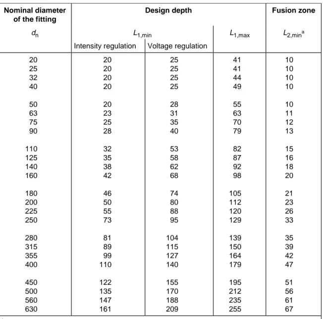
When measured in accordance with 6.1 the diameters and lengths of electrofusion sockets (see Figure 1) shall conform to Table 1.
Table 1 — Electrofusion socket dimensions
Dimensions in millimetres
Nominal diameter of the fitting
Design depth Fusion zone
dn L1,min L1,max L2,mina
Intensity regulation Voltage regulation
20 25 32 40 50 63 75 90 110 125 140 160 180 200 225 250 280 315 355 400 450 500 560 630 20 20 20 20 20 23 25 28 32 35 38 42 46 50 55 73 81 89 99 110 122 135 147 161 25 25 25 25 28 31 35 40 53 58 62 68 74 80 88 95 104 115 127 140 155 170 188 209 41 41 44 49 55 63 70 79 82 87 92 98 105 112 120 129 139 150 164 179 195 212 235 255 10 10 10 10 10 11 12 13 15 16 18 20 21 23 26 33 35 39 42 47 51 56 61 67 a
Increased fusion zone lengths are applicable for fittings rated to higher pressures, in order to meet the performance requirements of this standard
The manufacturer shall declare the actual maximum and minimum values of D1and L1to determine suitability for
clamping and joint assembly.
In the case of a fitting having sockets of differing sizes, each one shall conform to the requirements for the corresponding nominal diameter.
Key
D1 is the "mean inside diameter in the fusion zone" measured in a plane parallel to the plane of the mouth at a distance of L3 + 0,5L2; D2 is the bore which is the minimum diameter of the flow channel through the body of the fitting where D2≥ (dn− 2emin);
L1 is the "design penetration depth" of the pipe or male end of a spigot fitting. In the case of a coupling without a stop, it is not greater than half the total length of the fitting;
L2 is the heated length within a socket as declared by the manufacturer to be the nominal length of the fusion zone;
L3 is the distance between the mouth of the fitting and the start of the fusion zone as declared by the manufacturer to be the nominal unheated entrance length of the fitting L3 shall be ≥ 5 mm.
Figure 1 — Dimensions of electrofusion sockets 6.2.2 Wall thicknesses
The wall thickness of the body of the fitting at any point, E, shall be equal to or greater than emin for the
corresponding pipe for any part of the fitting located at a distance beyond 2L1/3 from all entrance faces of the fitting
when the fitting and the corresponding pipe are made from a polyethylene with the same designation. If the fitting is produced from a polyethylene with an MRS designation different from that of the corresponding pipe, the preferred
relationship between the wall thickness of the fitting, E, and the pipe, emin, shall conform to Table 2.
Table 2 — Relationship between pipe and fitting wall thicknesses Material
Pipe Fitting
Relationship between fitting wall thickness, E, and pipe wall thickness, emin
PE 80 PE 100 E ≥ 0,8emin
PE 100 PE 80 E ≥ 1,25emin
In order to prevent stress concentrations, any changes in wall thickness of the fitting body shall be gradual. NOTE Fittings conforming to ISO 8085-3 [5] are deemed to satisfy the requirements of this standard.
6.3 Dimensions of spigotted fittings
Table 3 — Spigot dimensions
Dimensions in millimetres
Mean outside diameter of the fusion end a
For electrofusion and butt fusion Socket fusion
For butt fusion only Nominal
outside diameter
of spigot Grade A Grade B
Out-of-roundness Min. bore Cut back length Tubular lengthb Tubular length Out-of-roundness Cut back length Tubular length Normal c Tubular length Special d dn D1,min D1,max D1,max max. D2 L1,min L2,min L2,min max. L1,min L2,min L2,min 20 25 32 40 50 63 75 90 110 125 140 160 180 200 225 250 280 315 355 400 450 500 560 630 20,0 25,0 32,0 40,0 50,0 63,0 75,0 90,0 110,0 125,0 140,0 160,0 180,0 200,0 225,0 250,0 280,0 315,0 355,0 400,0 450,0 500,0 560,0 630,0 — — — — — — — — — — — — — — — — 282,6 317,9 358,2 403,6 454,1 504,5 565,0 635,7 20,3 25,3 32,3 40,4 50,4 63,4 75,5 90,6 110,7 125,8 140,9 161,0 181,1 201,2 226,4 251,5 281,7 316,9 357,2 402,4 452,7 503,0 563,4 633,8 0,3 0,4 0,5 0,6 0,8 0,9 1,2 1,4 1,7 1,9 2,1 2,4 2,7 3,0 3,4 3,8 4,2 4,8 5,4 6,0 6,8 7,5 8,4 9,5 13 18 25 31 39 49 59 71 87 99 111 127 143 159 179 199 223 251 283 319 359 399 447 503 25 25 25 25 25 25 25 28 32 35 38 42 46 50 55 60 75 75 75 75 100 100 100 100 41 41 44 49 55 63 70 79 82 87 92 98 105 112 120 130 139 150 165 180 195 215 235 255 11 12,5 14,6 17 20 24 25 28 32 35 — — — — — — — — — — — — — — — — — — — 1,5 1,6 1,8 2,2 2,5 2,8 3,2 3,6 4,0 4,5 5,0 9,8 11,1 12,5 14,0 15,6 17,5 19,6 22,1 — — — — — 5 6 6 8 8 8 8 8 8 10 10 10 10 10 10 15 20 20 20 — — — — — 16 19 22 28 32 35 40 45 50 55 60 70 80 90 95 60 60 60 60 — — — — — 5 6 6 8 8 8 8 8 8 10 10 10 10 12 12 15 15 15 20 a
Tolerance grades A and B are in accordance with ISO 11922-1[6]. b
The values of L2 (electrofusion) are based on the following equations: for dn≤ 90, L2 = 0,6dn + 25 mm;
for dn≥ 110, L2 = dn/3 + 45 mm. c
Used by preference. d
Key
D1 is the "mean outside diameter" of the fusion end piece, measured in any plane parallel to the plane of the entrance face at a distance not greater than L2 (tubular length) from that plane;
D2 is the "minimum bore" which comprises the minimum diameter of the flow channel through the body of the fitting. The measurement of the diameter does not include the fusion pad if any;
E is the "body wall thickness of the fitting", which comprises the thickness measured at any point of the wall of the fitting; E1 is the "fusion face wall thickness" measured at any point at a maximum distance of L1 (cut back length) from the entrance face;
and shall be equal to the pipe wall thickness and tolerance to which it is intended to be butt fused as specified in Table 2 of EN 12201-2:2003;
L1 is the "cut back length" of the fusion end piece, which comprises the initial depth of the spigot end, which is necessary to butt fusion or reweld. This length may be obtained by joining a length of pipe to the spigot end of the fitting provided that the wall thickness of the pipe is equal to E1 for its whole length;
L2 is the "tubular length" of the fusion end piece, which comprises the initial length of the fusion end piece. This tubular length must allow (in any combination):
a) the use of clamps required in the case of butt fusion; b) the assembly with an electrofusion fitting;
c) the assembly with a socket fusion fitting; d) the use of a mechanical scraper.
Figure 2 — Dimensions of spigotted fittings
6.4 Dimensions of socket fusion fittings
For the description and dimensions of these types of fittings, see annex A.
6.5 Dimensions of electrofusion saddle fittings
Outlets from tapping tees and branch saddles shall have spigots in accordance with 6.3 or an electrofusion socket in accordance with 6.2. The manufacturer shall declare the overall characteristic dimension of the fitting in the technical file. These dimensions shall include the maximum height of the saddle, H, and the height of the service pipe measured from the top of the main, h, as shown in Figure 3.
Key
H is the height of the saddle, i.e. the distance from the top of the main to the top of the tapping tee;
h is the "height of service pipe", i.e. the distance between the top of the main pipe and the axis of the service pipe;
L is the "width of the tapping tee", i.e. the distance between the axis of the pipe and the plane of the mouth of the service tee.
Figure 3 — Dimensions of tapping tees
6.6 Dimensions of mechanical fittings
Mechanical fittings manufactured substantially from PE and intended for part fusion to PE pipe and part mechanical jointing to other pipe components, e.g. adapters, shall in at least one joint conform to the geometrical characteristics of the PE jointing system to be used.
NOTE Mechanical fittings not manufactured substantially from PE should conform to the requirements specified in the relevant standard(s).
6.7 Dimensions of loose backing flanges and flange adapters
Dimensions of loose backing flanges and flange adapters shall be in accordance with ISO 9624.
7
Mechanical characteristics
7.1 General
A fitting shall be tested assembled with pipe or as a part of an assembly of more than one fitting fused to pipe conforming to EN 12201-2:2003.
Each assembly shall be prepared from components (pipes and fittings) of the same pressure class and material classification.
7.2 Conditioning
Unless otherwise specified by the applicable test method, the test pieces shall be conditioned at (23 ± 2) °C before testing in accordance with Table 4.
7.3 Requirements
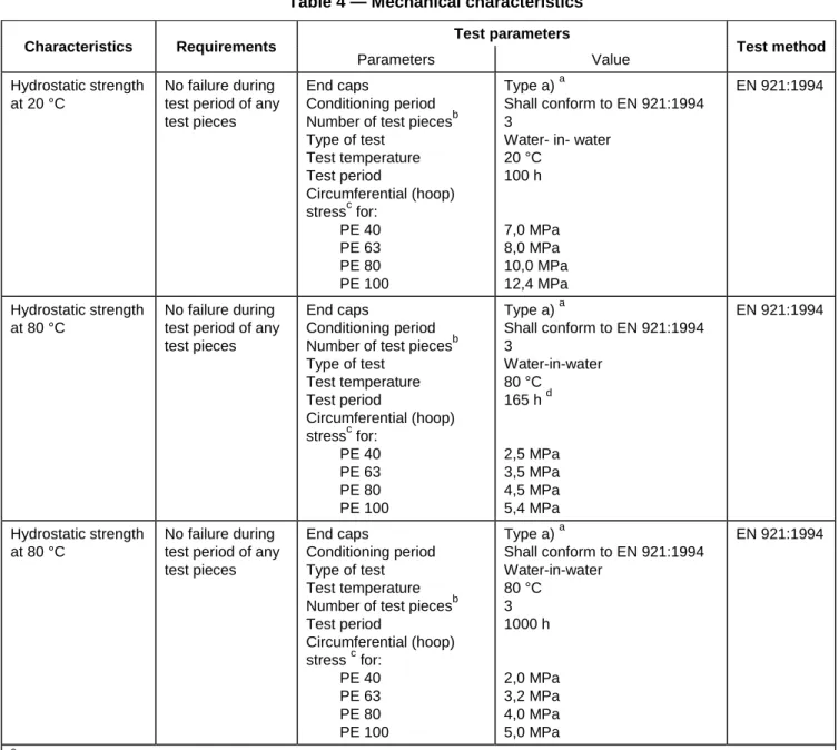
When tested in accordance with the test methods as specified in Table 4 using the parameters given in Table 4, the fitting shall have mechanical characteristics conforming to the requirements given in Table 4.
Table 4 — Mechanical characteristics
Test parameters Characteristics Requirements
Parameters Value Test method
Hydrostatic strength at 20 °C
No failure during test period of any test pieces
End caps
Conditioning period Number of test piecesb Type of test Test temperature Test period Circumferential (hoop) stressc for: PE 40 PE 63 PE 80 PE 100 Type a) a Shall conform to EN 921:1994 3
Water- in- water 20 °C 100 h 7,0 MPa 8,0 MPa 10,0 MPa 12,4 MPa EN 921:1994 Hydrostatic strength at 80 °C No failure during test period of any test pieces
End caps
Conditioning period Number of test piecesb Type of test Test temperature Test period Circumferential (hoop) stressc for: PE 40 PE 63 PE 80 PE 100 Type a) a Shall conform to EN 921:1994 3 Water-in-water 80 °C 165 h d 2,5 MPa 3,5 MPa 4,5 MPa 5,4 MPa EN 921:1994 Hydrostatic strength at 80 °C No failure during test period of any test pieces
End caps
Conditioning period Type of test Test temperature Number of test piecesb Test period Circumferential (hoop) stress c for: PE 40 PE 63 PE 80 PE 100 Type a) a Shall conform to EN 921:1994 Water-in-water 80 °C 3 1000 h 2,0 MPa 3,2 MPa 4,0 MPa 5,0 MPa EN 921:1994 a
Type b) end caps may be used for batch release tests for diameters ≥ 500 mm.
b
The number of test pieces given indicate the quantity required to establish a value for the characteristic described in the table. The number of test pieces required for factory production control and process control should be listed in the manufacturer’s quality plan (for guidance see prCEN/TS 12201-7[7]).
c
The stress shall be calculated using the dimensions of the pipe used in the test assembly.
d
Premature ductile failures are not taken into account. For retest procedure see 7.4.
7.4 Retest in case of failure at 80 °C
A fracture in a brittle mode in less than 165 h shall constitute a failure, however if a sample in the 165 h test fails in a ductile mode in less than 165 h, a retest shall be performed at a selected lower stress in order to achieve the minimum required time for the selected stress obtained from the line through the stress/time points given in Table 5.
Table 5 — Test parameters for the retest of the hydrostatic strength at 80 °C PE 40 PE 63 PE 80 PE 100
Stress Test period Stress Test period Stress Test period Stress Test period
MPa h MPa h MPa h MPa h
2,5 165 3,5 165 4,5 165 5,4 165 2,4 230 3,4 295 4,4 233 5,3 256 2,3 323 3,3 538 4,3 331 5,2 399 2,2 463 3,2 1000 4,2 474 5,1 629 2,1 675 4,1 685 5,0 1000 2,0 1000 4,0 1000
7.5 Pressure
drop
If required, the manufacturer shall declare the pressure drop of a fitting for sizes up to 63 when determined in accordance with ISO 4059:1978.
8
Physical characteristics
8.1 Conditioning
Unless otherwise specified by the applicable test method, the test pieces shall be conditioned at (23 ± 2) °C before testing in accordance with Table 6.
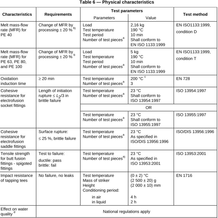
8.2 Requirements
When tested in accordance with the test methods as specified in Table 6 using the indicated parameters, the fittings shall have physical characteristics conforming to the requirements given in Table 6.
Table 6 — Physical characteristics
Test parameters Characteristics Requirements
Parameters Value Test method
Melt mass-flow rate (MFR) for PE 40 Change of MFR by processing ± 20 % b) Load Test temperature Test period
Number of test piecesa
2,16 kg 190 °C 10 min Shall conform to EN ISO 1133:1999 EN ISO1133:1999, condition D Melt mass-flow rate (MFR) for PE 63, PE 80, and PE 100 Change of MFR by processing ± 20 % b Load Test temperature Test period
Number of test piecesa 5 kg 190 °C 10 min Shall conform to EN ISO 1133:1999 EN ISO1133:1999, condition T Oxidation induction time
≥ 20 min Test temperature Number of test piecesa
200 °C c 3
EN 728 Test temperature
Number of test piecesa
23 °C Shall conform to ISO 13954:1997 ISO 13954:1997 OR Cohesive resistance for electrofusion socket fittings Length of initiation rupture ≤L2/3 in brittle failure Test temperature Number of test piecesa
23 °C Shall conform to ISO 13955:1997 ISO 13955:1997 Cohesive resistance for electrofusion saddle fittings Surface rupture: ≤ 25 %, brittle failure Test temperature Number of test piecesa
23 °C
As specified in ISO/DIS 13956:1996
ISO/DIS 13956:1996
Tensile strength for butt fusion fittings - spigoted fittings Test to failure: ductile: pass brittle: fail Test temperature Number of test piecesa)
23 °C As specified in ISO 13953:2001 ISO 13953:2001 Impact resistance of tapping tees
No failure, no leaks Test temperature Mass of striker Height Conditioning period: in air in liquid (0 ± 2) °C (2 500 ± 20) g (2 000 ± 10) mm 4 h 2 h EN 1716 Effect on water
quality d National regulations apply
a
The number of test pieces given indicate the quantity required to establish a value for the characteristic described in the table. The number of test pieces required for factory production control and process control should be listed in the manufacturer’s quality plan for guidance see prCEN/TS 12201-7[7].
b
Value as measured on the fitting relative to the value measured on the compound used.
c
Test may be carried out as an indirect test at 210 °C providing that there is clear correlation of the results to those at 200 °C: in cases of dispute the reference temperature shall be 200 °C.
d
Test methods, parameters and requirements for all properties are under preparation. Until these European Standards are published National Regulations apply (see introduction).
9
Chemical resistance of fittings in contact with chemicals
If for a particular installation it is necessary to evaluate the chemical resistance of fittings, then the fitting shall be classified in accordance with ISO 4433-1:1997 and ISO 4433-2:1997.
10 Performance requirements
When fittings conforming to this standard are assembled to each other or to components conforming to other Parts of this European Standard, the joints shall conform to the requirements given in EN 12201-5.
11 Marking
11.1 General
11.1.1 All fittings shall be permanently and legibly marked in such a way that the marking does not initiate cracks
or other types of failure.
11.1.2 If printing is used, the colour of the printed information shall differ from the basic colour of the product. 11.1.3 The marking shall be such that it is legible without magnification.
NOTE The manufacturer is not responsible for marking that is illegible, due to actions caused during installation and use such as painting, scratching, covering of components or using detergents etc on the components unless agreed or specified by the manufacturer.
11.1.4 There shall be no marking over the minimum spigot length of the fitting.
11.2 Minimum required marking of fittings
The minimum required marking shall conform to Table 7.
NOTE Attention is drawn to the possible need to include CE marking when required for legislative purposes.
Table 7 — Minimum required marking on the fitting Aspects Marking or symbol
Manufacturer's name or trade mark Name or code
Nominal diameter and pipe series/SDR e.g.dn 110/S 5 or
dn 110/SDR 11
Manufacturer's information SDR fusion range
Material and designation
a
e.g. SDR 11 – SDR 26 b
e.g. PE 80 b
a In clear figures or in code providing traceability to production period within
year and month and the production site if manufacturer is producing at different sites nationally and/or internationally.
b This information may be printed on a label attached to the fitting or on an
individual bag (see Table 8).
11.3 Minimum required marking on a label
The following additional information given in Table 8 may be printed on a label, with one label attached to the fitting or to the individual bag. The label shall be of sufficient quality to be intact and legible at the time of installation.
Table 8 — Minimum required marking on the label
Aspects Marking or symbol
Standard number EN 12201
Material and designation e.g. PE 80
Pressure rating in bars e.g. PN 12,5
Tolerance (only for spigot fittings) dn≥ 280 mm e.g. Grade A
SDR fusion range e.g SDR 11 – SDR 26 a
a This information may be printed on the fitting (see Table 7).
11.4 Fusion system recognition
Fusion fittings should have a system, either numerical or electromechanical or self regulatory, for recognising the fusion parameters to facilitate the fusion process.
Where bar-codes are used for the numerical recognition, the bar-code label shall be stuck to the fitting and shall be protected against deterioration.
12 Packaging
The fitting shall be packaged in bulk or individually protected where necessary in order to prevent deterioration and contamination.
The packaging shall have at least one label with the manufacturer’s name, type and dimensions of the part, number of units and any special storage conditions.
Annex A
(normative)
Socket fusion fittings
When applicable the dimensions of socket fusion fittings shall conform to the following tables. The diameter at the root shall not be greater than the diameter at the mouth.
Table A.1 — Socket dimensions for nominal sizes 16 to 63 inclusive
Dimensions in millimetres Mean inside diameter of socket
Mouth Root Out-of- round-ness Min. bore Socket reference length Heated socket length a Penetration of pipe into socket
b Nom. size DN/OD Nominal inside diameter of
socket D1,min D1,max D2,min D2,max max. D3 L min L2,min L2,max L3,min L3,max
16 16 15,2 15,5 15,1 15,4 0,4 9 13,3 10,8 13,3 9,8 12,3 20 20 19,2 19,5 19,0 19,3 0,4 13 14,5 12,0 14,5 11,0 13,5 25 25 24,1 24,5 23,9 24,3 0,4 18 16,0 13,5 16,0 12,5 15,0 32 32 31,1 31,5 30,9 31,3 0,5 25 18,1 15,6 18,1 14,6 17,1 40 40 39,0 39,4 38,8 39,2 0,5 31 20,5 18,0 20,5 17,0 19,5 50 50 48,9 49,4 48,7 49,2 0,6 39 23,5 21,0 23,5 20,0 22,5 63 63 62,0 c 62,4 c 61,6 62,1 0,6 49 27,4 24,9 27,4 23,9 26,4
a L2,min = (Lmin - 2,5) mm; L2,max = Lmin mm. b L3,min = (Lmin - 3,5) mm; L3,max = (Lmin - 1) mm.
C Where rerounding clamps are used, the maximum diameter of 62,4 mm may be increased by 0,1 mm to 62,5 mm. Conversely, where a peeling technique is used, the minimum diameter of 62,0 mm may be reduced by 0,1 mm to 61,9 mm.
Table A.2 — Socket dimensions for fittings nominal sizes 75 to 125 inclusive
Dimensions in millimetres Mean inside diameter of socket
Mean outside diameter of pipe Nominal inside diameter of socket Mouth Root Min. bore Socket ref. length Heated socket length a Penetration of pipe into socket a Nom. size DN/OD
dem,min dem,max dn D1,min D1,max D2,min D2,max
Out- of-
round-ness
D3 Lmin L2,min L2,max L3,min L3,max
75 75,0 75,5 75 74,3 74,8 73,0 73,5 0,7 59 30 26 30 25 29
90 90,0 90,6 90 89,3 89,9 87,9 88,5 1,0 71 33 29 33 28 32
110 110,0 110,6 110 109,4 110,0 107,7 108,3 1,0 87 37 33 37 32 36
125 125,0 125,6 125 124,4 125,0 122,6 123,2 1,0 99 40 36 40 35 39
a
L2,min = (Lmin - 4) mm; L2,max = Lmin mm. b
Key
D1 is the "mean inside mouth diameter" of the socket, i.e. the means diameter of the circle at the inter section of the extension of the socket with the plane of the socket mouth;
D2 is the "mean inside root diameter" of the socket, i.e. the mean diameter of the circle in a plane parallel to the plane of the mouth and separated from it by a distance of L, which is the reference length of the socket;
D3 is the "minimum bore", i.e. the minimum diameter of the flow channel through the body of the fitting;
L is the "reference socket length" i.e. the theoretical minimum socket length used for the purpose of calculation; L1 is the "actual length of the socket" from mouth to shoulder, if any;
L2 is the "heated length of the fitting" i.e. the length of penetration of the heated tool into the socket.; L3 is the "insertion depth" i.e. the depth of the heated pipe end into the socket;
L4 is the "heated length of pipe" i.e. the depth of penetration of the pipe end into the heated tool.
Annex B
(informative)
Examples of typical terminal connection for electrofusion fittings
Figures B.1 and B.2 illustrate examples of terminal connections suitable for use with voltages less than or equal to 48 V (types A and B).
Dimensions in millimetres
Key
A is active zone
C1 outside diameter of the terminal shroud C1≥ 11,8 C2 diameter of the active part of the terminal C2 = 4,0 ± 0,03 C3 internal diameter of the terminal shroud C3 = 9,5 ± 1,0 C4 maximum overall diameter of the base C4≤ 6,0 H internal depth of the terminal shroud H ≥ 12,0 H1 distance between the upper part of H1 = 3,2 ± 0,5
the terminal and the active part
Dimensions in millimetres
Key
C1 outside diameter of the terminal shroud C1 = 13,0 ± 0,05 C2 diameter of the active part of the C2 = 4,7 ± 0,03
terminal
C3 internal diameter of the terminal shroud C3 = 10,0
5 , 0 0
H internal depth of the terminal shroud H ≥ 15,5 H1 distance between the upper part of H1 = 4,5 ± 0,5
the terminal shroud and the active part
Figure B.2 — Typical type B connection
Figure B.3 illustrates an example of a typical electrofusion terminal connection suitable for use with voltages up to 250 V (type C).
Dimensions in millimetres
Key
C1 outside diameter of the terminal C1≥ C3 + 2,0 C2 diameter of the active part of the terminal C2≥ 2,0 C3 internal diameter of the terminal C3≥ C2 + 4,0
H1 distance between the upper part of the H1 sufficient to ensure a degree of protection of I P 2 × as defined in EN 60947-1[9]) terminal and the active part
H2 is the height of the active part H2 ≥ 7,0
Bibliography
[1] EN 60335-1, Safety of household and similar electrical appliances — Part 1: General requirements
(IEC 60335-1:1991, modified).
[2] IEC 60364-1, Electrical installations of buildings - Part 1: Fundamental principles, assessment of general
characteristics, definitions.
[3] IEC 60449, Voltage bands for electrical installations of building.
[4] EN 60529, Degree of protection provided by enclosures (IP Code) (IEC 60529:1989).
[5] ISO 8085-3, Polyethylene fittings for use with polyethylene pipes for the supply of gaseous fuels –Metric
series – Specifications – Part 3: Electrofusion fittings.
[6] ISO 11922-1, Thermoplastics pipes for the conveyance of fluids — Dimensions and tolerances — Part 1:
Metric series.
[7] prCEN/TS 12201-7, Plastics piping systems for water supply — Polyethylene (PE) — Part 7: Guidance for
the assessment of conformity.
[8] ISO/TR 10358, Plastics pipes and fittings — Combined chemical-resistance classification table.
[9] EN 60947-1, Low-voltage switchgear and control gear — Part 1: General rules (IEC 60947-1:1999,
National Annex NA (informative)
Additional information on the selection and installation of piping systems and
components in the UK
The responsible UK committee gives the following advice concerning the selection
and installation of piping systems and components conforming to this British
Standard.
a) Water supply companies and other entities deemed to be within the scope of
the Public Procurement Directive (PPD) are obliged to use EN 12201-1,
EN 12201-2, EN 12201-3, EN 12201-4 and EN 12201-5 produced under
EC/U mandate, if they wish to purchase PE pipe systems or components
within its scope.
b) Where there are options, care should be taken to ensure that agreement is
established between suppliers and purchasers, e.g. in terms of colour, size,
physical characteristics, effect on water quality and quality assurance.
c) It is the practice of UK water companies to use blue coloured PE pipes and
fittings as specified in WIS 4-32-14 [1] to facilitate identification of buried
potable water pipelines in accordance with the recommendations of the
National Joint Utilities Group (NJUG) concerning the colour coding of
pipelines and other services.
d) Attention is drawn to Note a to Table 1 concerning fusion zone lengths. For
applications within the UK water industry suitable minimum fusion lengths
are specified in WIS 4-32-14 [1].
e) The use of pipes and components manufactured in PE 40 and PE 63
materials is not established practice in the UK.
f) It has been UK practice to specify a test to guard against leakage or
contamination as a result of biodegradation of elastomeric sealing rings or
gaskets used in piping systems. This requirement is specifically excluded
from the scope of BS EN 681-1. For manufacturers wishing to demonstrate
resistance of such products to biodegradation, a test is contained in
BS 7874.
g) The minimum lengths of spigots specified in Table 3 do not allow for the
use of mechanical scrapers. Spigot lengths which do allow for this are
specified in WIS 4-32-15 [2].
h) With reference to
4.2.1
, in those cases where there is no relevant European
standard, an appropriate specification for use in the UK for component parts
made from thermoplastic materials other than PE is provided in
WIS 4-32-11 (Issue 2) [3].
i) The electrical characteristics for electrofusion fittings are loosely specified
in
5.4
. It is current UK practice to specify 4.7 mm diameter electrofusion
terminal pins in association with an applied voltage of 39 V to 40 V and
with a maximum power requirement for the 40 V fittings of 2.5 kW (this
aligns with WIS 4-32-14 [1]).
.81.1130 SB 3-10221 NE xenna.odc
gaPe 2 2 fo
National bibliography
Standards publications
BS 7874:1998,
Method of test for microbiological deterioration of elastomeric seals
for joints in pipework and pipelines.
BS EN 681-1:1996,
Elastomeric seals — Material requirements for pipe joint seals
used in water and drainage applications — Part 1: Vulcanized rubber.
Other publications
[1] WRc. WIS 4-32-14,
Specification for PE 80 and PE 100 electrofusion fittings for
nominal sizes up to and including 630
. Swindon: WRc, 1995.
[2] WRc. WIS 4-32-15,
Specification for PE 80 and PE 100 spigot fittings and drawn
bends for nominal sizes up to and including 1000
. Swindon: WRc, 1995.
[3] WRc. WIS 4-32-11 (Issue 2),
Specification for thermoplastic end-load resistant
mechanical joints for polyethylene pipes of nominal size
≤
63
. Swindon: WRc,
1999.
26
BSI
389 Chiswick High Road London
W4 4AL
BSI — British Standards Institution
BSI is the independent national body responsible for preparingBritish Standards. It presents the UK view on standards in Europe and at the international level. It is incorporated by Royal Charter.
Revisions
British Standards are updated by amendment or revision. Users of
British Standards should make sure that they possess the latest amendments or editions.
It is the constant aim of BSI to improve the quality of our products and services. We would be grateful if anyone finding an inaccuracy or ambiguity while using this British Standard would inform the Secretary of the technical committee responsible, the identity of which can be found on the inside front cover. Tel: +44 (0)20 8996 9000. Fax: +44 (0)20 8996 7400.
BSI offers members an individual updating service called PLUS which ensures that subscribers automatically receive the latest editions of standards.
Buying standards
Orders for all BSI, international and foreign standards publications should be addressed to Customer Services. Tel: +44 (0)20 8996 9001.
Fax: +44 (0)20 8996 7001. Email: orders@bsi-global.com. Standards are also available from the BSI website at http://www.bsi-global.com.
In response to orders for international standards, it is BSI policy to supply the BSI implementation of those that have been published as British Standards, unless otherwise requested.
Information on standards
BSI provides a wide range of information on national, European and
international standards through its Library and its Technical Help to Exporters Service. Various BSI electronic information services are also available which give details on all its products and services. Contact the Information Centre.
Tel: +44 (0)20 8996 7111. Fax: +44 (0)20 8996 7048. Email: info@bsi-global.com. Subscribing members of BSI are kept up to date with standards developments and receive substantial discounts on the purchase price of standards. For details of these and other benefits contact Membership Administration.
Tel: +44 (0)20 8996 7002. Fax: +44 (0)20 8996 7001. Email: membership@bsi-global.com.
Information regarding online access to British Standards via British Standards Online can be found at http://www.bsi-global.com/bsonline.
Further information about BSI is available on the BSI website at http://www.bsi-global.com.
Copyright
Copyright subsists in all BSI publications. BSI also holds the copyright, in the UK, of the publications of the international standardization bodies. Except as permitted under the Copyright, Designs and Patents Act 1988 no extract may be reproduced, stored in a retrieval system or transmitted in any form or by any means – electronic, photocopying, recording or otherwise – without prior written permission from BSI.
This does not preclude the free use, in the course of implementing the standard, of necessary details such as symbols, and size, type or grade designations. If these details are to be used for any other purpose than implementation then the prior written permission of BSI must be obtained.
Details and advice can be obtained from the Copyright & Licensing Manager. Tel: +44 (0)20 8996 7070. Fax: +44 (0)20 8996 7553.