PORT POWERED
SWIPE READER
TECHNICAL REFERENCE MANUAL
Manual Part Number 99875094 Rev 16
FEBRUARY 2007 REGISTERED TO ISO 9001:2000 1710 Apollo Court Seal Beach, CA 90740 Phone: (562) 546-6400 FAX: (562) 546-6301 Technical Support: (651) 415-6800 www.magtek.com
Copyright 1997-2007 MagTek®, Inc.
Printed in the United States of America
Information in this document is subject to change without notice. No part of this document may be reproduced or transmitted in any form or by any means, electronic or mechanical, for any purpose, without the express written permission of MagTek, Inc.
MagTek is a registered trademark of MagTek, Inc.
Procomm is a registered trademark of Datastorm Technologies, Inc.
REVISIONS Rev
Number
Date Notes 1 11 Dec 97 Initial Release
2 18 Dec 97 Sec 1 Changed spec Dimensions; Sec 1, 3 Changed illustrations for clarity. 3 11 May 98 Sections 1, 2, and 3 revised to reflect latest firmware revisions. Sec 4 deleted. 4 15 Jun 98 Two part numbers added.
5 1 Mar 99 Sec 1, Added 3 part numbers, changed specs, Changed Dimensions Figure 1-3, removed Figure 1-4, Mounting Dimensions, added MagTek Windows Drivers; Added note to Table 1-1. Section 2, added mounting instructions and Figure 2-1, Mounting Dimensions. Section 3, added 3 track symbols to Table 3-1 and 3 sign-on
configurations to 3-2.
6 14 Jun 99 Title change, Removed MT-211 and RS-232; Sec 1, Table 1-1, added Pin List for Cable 21040077, added RS-232 Communication; Sec 2, added Demo Program from Net; Sec 3, Clarified Fig 3-1, Described firmware P/Ns and revisions.
7 1 Dec 99 Section 1: Added P/N 21040084, Updated table for 9- and 25-pin connectors; Section 3: Added P/N 21040084 to Sign-on table.
8 21 Sep 00 Editorial changes throughout. Sec 1: Configuration list expanded and moved to Sec 3; Specification weight changed from 5.9 oz to 5.8oz, Converted symbols to Metric System [SI]. Sec 3: Added 5 new part numbers with firmware, tracks, and
configurations.
9 09 Mar 01 Front Matter: Corrected Agency Approvals to include Class B for FCC and Class B for CE. Changed RMA Warranty address to 20801 S. Annalee. Section 3: Removed “Track 3 – 7 bit” line from Table 3-1. Added 094 and 096 configurations in Table 3-2. 10 25 Jul 01 Front Matter: Agency Approvals: Corrected Class B for CE and Corrected UL and
CUL. Copyright 2001 added.
11 24 Apr 03 Front Matter: added ISO line to logo, changed Tech Support phone number, added new warranty statement; Sec 3: added 2 new part numbers at the end of Table 3-2. 12 23 Jun 03 Editorial throughout. Section 3: Removed the following parts from Table 3-2:
21040073, 21040077, 21040084, 21040089. 13 11 May 04 Sec 1: Specifications, corrected cable length.
14 10 Jan 06 Updated specifications to reflect new models. Added commands to support modification of properties (Section 4).
15 23 Feb 06 Sec 3: Timing for Sign-on ID changed from 150 to a range from 150 to 330ms. Sec 4: Sending of <CR> when using Reset Device Command follows SB switch setting.
LIMITED WARRANTY
MagTek warrants that the products sold to Reseller pursuant to this Agreement will perform in accordance with MagTek’s published specifications. This warranty shall be provided only for a period of one year from the date of the shipment of the product from MagTek (the “Warranty Period”). This warranty shall apply only to the original purchaser unless the buyer is authorized by MagTek to resell the products, in which event, this warranty shall apply only to the first repurchase.
During the Warranty Period, should this product fail to conform to MagTek’s specifications, MagTek will, at its option, repair or replace this product at no additional charge except as set forth below. Repair parts and
replacement products will be furnished on an exchange basis and will be either reconditioned or new. All replaced parts and products become the property of MagTek. This limited warranty does not include service to repair damage to the product resulting from accident, disaster, unreasonable use, misuse, abuse, customer’s negligence, Reseller’s negligence, or non-MagTek modification of the product. MagTek reserves the right to examine the alleged defective goods to determine whether the warranty is applicable.
Without limiting the generality of the foregoing, MagTek specifically disclaims any liability or warranty for goods resold in other than MagTek’s original packages, and for goods modified, altered, or treated by customers. Service may be obtained by delivering the product during the warranty period to MagTek (1710 Apollo Court, Seal Beach, CA 90740). If this product is delivered by mail or by an equivalent shipping carrier, the customer agrees to insure the product or assume the risk of loss or damage in transit, to prepay shipping charges to the warranty service location and to use the original shipping container or equivalent. MagTek will return the product, prepaid, via a three (3) day shipping service. A Return Material Authorization (RMA) number must accompany all returns.
MAGTEK MAKES NO OTHER WARRANTY, EXPRESS OR IMPLIED, AND MAGTEK DISCLAIMS ANY WARRANTY OF ANY OTHER KIND, INCLUDING ANY WARRANTY OF MERCHANTABILITY OR FITNESS FOR A PARTICULAR PURPOSE.
EACH PURCHASER UNDERSTANDS THAT THE MAGTEK PRODUCT IS OFFERED AS IS. IF THIS PRODUCT DOES NOT CONFORM TO MAGTEK’S SPECIFICATIONS, THE SOLE REMEDY SHALL BE REPAIR OR REPLACEMENT AS PROVIDED ABOVE. MAGTEK’S LIABILITY, IF ANY, TO RESELLER OR TO RESELLER’S CUSTOMERS, SHALL IN NO EVENT EXCEED THE TOTAL AMOUNT PAID TO MAGTEK BY RESELLER UNDER THIS AGREEMENT. IN NO EVENT WILL MAGTEK BE LIABLE TO THE RESELLER OR THE RESELLER’S CUSTOMER FOR ANY DAMAGES, INCLUDING ANY LOST PROFITS, LOST SAVINGS OR OTHER INCIDENTAL OR CONSEQUENTIAL DAMAGES ARISING OUT OF THE USE OF OR INABILITY TO USE SUCH PRODUCT, EVEN IF MAGTEK HAS BEEN ADVISED OF THE POSSIBILITY OF SUCH DAMAGES, OR FOR ANY CLAIM BY ANY OTHER PARTY.
LIMITATION ON LIABILITY
EXCEPT AS PROVIDED IN THE SECTIONS RELATING TO MAGTEK’S LIMITED WARRANTY, MAGTEK’S LIABILITY UNDER THIS AGREEMENT IS LIMITED TO THE CONTRACT PRICE OF THE PRODUCTS.
MAGTEK MAKES NO OTHER WARRANTIES WITH RESPECT TO THE PRODUCTS, EXPRESSED OR IMPLIED, EXCEPT AS MAY BE STATED IN THIS AGREEMENT, AND MAGTEK DISCLAIMS ANY IMPLIED WARRANTY, INCLUDING WITHOUT LIMITATION ANY IMPLIED WARRANTY OF MERCHANTABILITY OR FITNESS FOR A PARTICULAR PURPOSE.
MAGTEK SHALL NOT BE LIABLE FOR CONTINGENT, INCIDENTAL, OR CONSEQUENTIAL
DAMAGES TO PERSONS OR PROPERTY. MAGTEK FURTHER LIMITS ITS LIABILITY OF ANY KIND WITH RESPECT TO THE PRODUCTS, INCLUDING ANY NEGLIGENCE ON ITS PART, TO THE
CONTRACT PRICE FOR THE GOODS.
FCC WARNING STATEMENT
This equipment has been tested and found to comply with the limits for Class B digital device, pursuant to Part 15 of FCC Rules. These limits are designed to provide reasonable protection against harmful interference when the equipment is operated in a residential environment. This equipment generates, uses, and can radiate radio frequency energy and, if not installed and used in accordance with the instruction manual, may cause harmful interference to radio communications. However, there is no guarantee that interference will not occur in a particular installation.
FCC COMPLIANCE STATEMENT
This device complies with Part 15 of the FCC Rules. Operation of this device is subject to the following two conditions: (1) This device may not cause harmful interference; and (2) this device must accept any interference received, including interference that may cause undesired operation.
CANADIAN DOC STATEMENT
This digital apparatus does not exceed the Class B limits for radio noise for digital apparatus set out in the Radio Interference Regulations of the Canadian Department of Communications.
Le présent appareil numérique n’émet pas de bruits radioélectriques dépassant les limites applicables aux appareils numériques de las classe B prescrites dans le Réglement sur le brouillage radioélectrique édicté par les ministère des Communications du Canada.
CE STANDARDS
Testing for compliance to CE requirements was performed by an independent laboratory. The unit under test was found compliant to Class B.
UL/CSA
TABLE OF CONTENTS
SECTION 1. FEATURES AND SPECIFICATIONS --- 1
MAGTEK DEVICE DRIVERS FOR WINDOWS --- 1
FEATURES --- 2 CONFIGURATION--- 2 SPECIFICATIONS --- 4 SECTION 2. INSTALLATION --- 7 REQUIREMENTS--- 7 MOUNTING--- 7
INSTALLATION AND TEST --- 8
SECTION 3. OPERATION ---11
LED INDICATOR---11
CARD READ ---11
READER TO HOST MESSAGE FORMAT ---11
TIMING FOR ID SIGN ON ---12
SECTION 4. PROPERTIES AND COMMANDS ---15
SENDING COMMANDS---15 XON/XOFF---15 RESET DEVICE ---16 VERSION REQUEST ---16 UPLOAD COMMAND ---16 CONFIGURATION COMMANDS ---17 Switch A---18 Switch B---19 Switch C---20 Sentinel Definitions ---20
FIGURES AND TABLES Figure 1-1. Port-Powered Swipe Reader--- vi
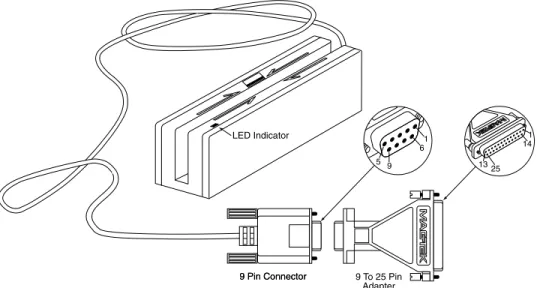
Figure 1-2. Reader Cable and Optional Adapter --- 2
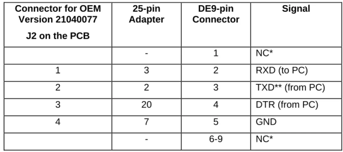
Table 1-1. OEM and 9-Pin Connectors and 25-Pin Adapter --- 3
Table 1-2. Specifications --- 4
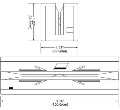
Figure 1-3. Dimensions--- 5
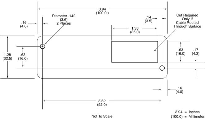
Figure 2-1. Mounting Hole Dimensions for Surface --- 8
Table 3-1. SS and ES Track Symbols ---11
Figure 3-1. Timing For ID Sign-on and Transmission Bursts (Old version). ---12
Table 3-2. Sign-on ID for Configurations ---13
Table 4-1. Switch A---18
Table 4-2. Switch B---19
Table 4-3. Switch C---20
SECTION 1. FEATURES AND SPECIFICATIONS
The Port Powered Swipe Reader is a compact magnetic stripe card reader which conforms to ISO/ANSI standards. The Reader is compatible with the PC series of personal computers or any device with a serial RS-232 interface. A card is read by sliding it, stripe down and facing the LED side, through the slot either forward or backward.
A green/red LED (Light Emitting Diode) indicator on the Reader panel provides the operator with continuous status of the Reader operations.
When power is applied, the Reader transmits a sign-on ID message. About 150 to 330 milliseconds after DTR is applied, the Reader sends the part number of the firmware in the following form: 210888xxAnn<CR>. The first 8 characters indicate the firmware number; the letter is the revision, which is followed by a revision sublevel of 01 to 99. The <CR> indicates carriage return (0x0D). The sign-on messages for part numbers are listed in Section 3. Timing is also shown in Section 3.
Note
Additional features have been incorporated into the new version of the Port Powered Swipe Reader (generally available after March 2006). In the new version, the firmware part number will be reported as 21088838. The enhancements included in this new version are identified within this document with the word “new”.
Since the input voltage is supplied by a relatively low source of power, the Reader depends on its input capacitor to maintain proper charge during all operations. In the old model, in order to reduce the drain on this internal power source during data transmission, the output data is transmitted in 5 to 6 millisecond bursts with a 10-millisecond gap between bursts to allow the capacitor to recharge. The PC software should be able to tolerate this 10-millisecond space between characters. The Timing is shown is Section 3, Figure 3-1. In the new version, with its lower current draw, the data is transmitted continuously since there is no need to transmit in bursts. Configurations, including part numbers, firmware, tracks, and unit configuration, are listed in Section 3, Table 3-2.
MAGTEK DEVICE DRIVERS FOR WINDOWS
The MagTek Device Drivers for Windows may be used with the Port Powered Swipe Reader. They are available on a CD (Part Number 30037385) or from the MagTek web site (Part Number 99510013). When these drivers are used, refer to MagTek Device Driver for Windows,
FEATURES
Major features of the Swipe Reader are as follows:
•
Powered through the RS-232 serial port – no external power supply required•
Hardware Compatible with PC or any computer or terminal with an RS-232 interface•
Software Compatible with the MagTek MTD Windows Device Drivers or any RS-232 communications program•
Bidirectional card reading•
Reads encoded data that meets ANSI/ISO/AAMVA standards•
Green/Red LED for statusCONFIGURATION
The Reader, LED Indicator, pin numbers for the 9-pin connector and the 25-pin adapter are shown in Figure 1-2.
Section 1. Features and Specifications
Pin numbers and signal descriptions for the 9-pin (DE9) cable and 25-pin (DB25) adapter shown in the illustration are listed in Table 1-1. Also listed is the pin list OEM version, P/N 21040077.
Table 1-1. OEM and 9-Pin Connectors and 25-Pin Adapter Connector for OEM
Version 21040077 J2 on the PCB 25-pin Adapter DE9-pin Connector Signal - 1 NC* 1 3 2 RXD (to PC) 2 2 3 TXD** (from PC) 3 20 4 DTR (from PC) 4 7 5 GND - 6-9 NC* * No Connection
SPECIFICATIONS
Table 1-2 lists the specifications for the Port Powered Swipe Reader. Figure 1-3 shows the dimensions for the standard product. Other sizes are available by special order.
Table 1-2. Specifications OPERATING
Reference Standards ISO/ANSI/AAMVA* Power Input From RS-232 interface
Recording Method Two-frequency coherent phase (F2F) Message Format ASCII
Card Speed 3 to 60 in/s (7.6 to 152.4 cm/s) – forward or reverse Head Life 1,000,000 passes
ELECTRICAL
Old Version New Version
DTR Voltage 5 to 15 VDC 4 to 15 VDC (+/-24 VDC absolute max) Current Quiescent Transmit/Read Peak at Power On 1 to 2 mA typical (continuous) 8 to 9 mA typical (5 ms duration) 12 mA 7 mA maximum (continuous) 11 mA maximum
Limited by source (~50 µF load) RS-232 Communication 9600 bps 8N1 Adjustable (default 9600 bps 8N1)
MECHANICAL (STANDARD PRODUCT) Dimensions Length: 3.94” (100.0 mm)
Width: 1.28” (32.5 mm) Height: 1.23” (31.3 mm) Weight Reader 5.8 oz. (165 gr.) Cable length See Table 3-2
Connector 9 pin D female
ENVIRONMENTAL
Temperature Old Version New Version
Operating 32oF to 131oF (0oC to 55oC) 32oF to 158oF (0oC to 70oC) Storage -22oF to 158oF (-30oC to 70oC) -22oF to 158oF (-30oC to 70oC) Humidity
Operating 10% to 90% noncondensing 10% to 90% noncondensing Storage 10% to 90% noncondensing 10% to 90% noncondensing * ISO (International Standards Organization), ANSI (American National Standards Institute), and
Section 1. Features and Specifications
SECTION 2. INSTALLATION
The hardware installation consists of plugging the cable into the PC and optional 25-pin adapter, if required, Com Port setup, and testing the Reader.
REQUIREMENTS
•
Port Powered Swipe Reader•
Optional 9- to-25-pin Adapter, P/N 78200018•
PC with Serial RS-232 Com Port•
MagTek Windows Drivers or any RS-232 communications programMOUNTING
1. The Reader can be mounted on a surface in three ways:
•
By two screws through the surface attached to the bottom of the unit and running the cable on the top of the surface•
By two screws through the surface attached to the bottom of the unit and by drilling a hole in the surface for the cable and running the cable through the hole•
By attaching the unit to the surface with 3M™ Dual Lock™ fasteners (or equivalent) and running the cable on the top of the surfaceNote
The two mounting inserts are 3 mm diameter; 0.5 mm pitch; 6.4 mm deep. The length of the screws used depends on the mounting surface thickness and the thickness of washers (if used).
The mounting dimensions are shown in Figure 2-1. Determine the method of mounting required.
2. Ensure the Reader is positioned on a flat, accessible surface with at least 4 inches clearance on either end for room to swipe a card. Orient the Reader so the side with the LED is facing the direction of intended use.
If fastening tape is to be used, clean the area that the Reader will be mounted on with isopropyl alcohol. Remove the adhesive protective cover on the fastening tape, and position the Reader and push down firmly.
Figure 2-1. Mounting Hole Dimensions for Surface
3. Mount the Reader.
INSTALLATION AND TEST
To install the Swipe Reader, perform the following steps:
1. Connect the Swipe Reader cable connector into a 9-pin serial Com Port on the PC. If a 25-pin Adapter is required, plug the 9-pin connector on the Reader into the Adapter and the adapter into the PC.
2. Open a communications program such as the MagTek Encoder/Reader Demonstration Program, which may be obtained from the Internet at www.magtek.com. Navigate to the Demo Programs and select Encoder/Reader Demo.
Section 2. Installation
6. Select 8 data bits, no parity, 1 stop bit. (With the new version, this setting can be adjusted as required.)
7. With the LED on, swipe a card. The data on the screen will show Track 1 beginning with “%” and ending with “?”. Track 2 begins with “;” and ends with “?”. Track 3 begins with “+” (normal) or "!" (CDL) and ends with “?”. The following is an example:
%B123^Smith/Joann^9812101000?;112222333333444444444?<0x0D> If a track cannot be read, an E will appear in place of the track data; for example, if Track 2 is bad and Tracks 1 and 3 are good, the display will be similar to the following:
%11111111111111111111?;E?+3333333333333333333?<0x0D> If Tracks 1 and 3 are bad and Track 2 is good, the display will be similar to the following:
%E?;22222222222222222222?+E?<0x0D>
8. If the data on the screen is not numeric or alphanumeric similar to the above, check the communications rate. If the alphanumeric characters are similar to the above, the unit is ready for operation.
SECTION 3. OPERATION
Included in this section are Indicator, Card Read, Reader to Host Message Format, and a timing diagram of sign-on ID.
LED INDICATOR
A green/red LED indicator on the panel gives the operator the status of the Reader. If the cabling is correct and the correct Com Port is selected, the indicator will show green. If the indictor does not come on, check the cabling and the Com Port. The LED is turned off while the unit is transmitting. If an error has been detected while reading the card, the LED will
momentarily show red.
CARD READ
A card may be swiped through the Reader slot when the green LED is lit. The magnetic stripe must face toward the front (the side with the LED) and may be swiped in either direction.
READER TO HOST MESSAGE FORMAT
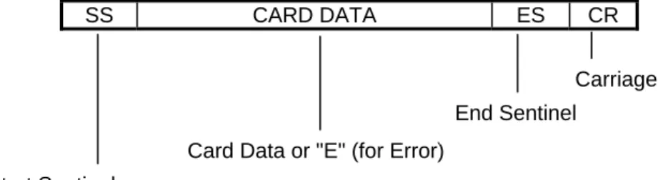
Track data is sent in the following order: SS, Card Data, ES.
The format in which data is transmitted (in track order) after a card is read successfully is as follows:
SS CARD DATA ES CR
Table 3-1 lists the default Start Sentinel and End Sentinel symbols.
Table 3-1. SS and ES Track Symbols Start Sentinel End Sentinel Description
% ? Track 1
; ? Track 2
+ ? Track 3 - ISO # ? Track 3 - AAMVA Start Sentinel
Card Data or "E" (for Error)
End Sentinel
TIMING FOR ID SIGN ON
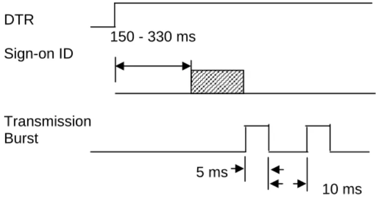
Timing for the ID Sign-on and transmission bursts (5 ms with 10 ms between bursts) are shown in Figure 3-1.
Note
The “Transmission Burst” timing shown in Figure 3-1 only applies to the old version of the Reader. The new version does not apply the 10 ms gap between transmission bursts but rather transmits the full message without any delays. The Sign-on ID delay is in the range between 150 to 330 milliseconds.
DTR 150 - 330 ms Sign-on ID Transmission Burst 5 ms 10 ms
Figure 3-1. Timing For ID Sign-on and Transmission Bursts (Old version).
The firmware controls the operation of Sign-on ID and Transmission bursts in the following format:
210888xxLnn<CR> Where:
the first 8 digits are the firmware part number
xx represents the Swipe Reader series
Section 3. Operation
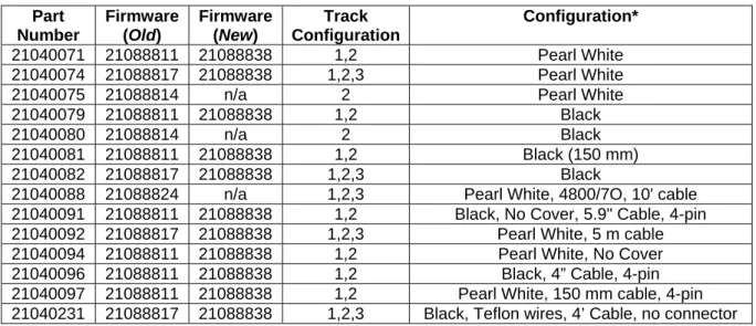
Table 3-2 lists the available part number, firmware, and configuration.
Table 3-2. Sign-on ID for Configurations Part Number Firmware (Old) Firmware (New) Track Configuration Configuration* 21040071 21088811 21088838 1,2 Pearl White 21040074 21088817 21088838 1,2,3 Pearl White 21040075 21088814 n/a 2 Pearl White 21040079 21088811 21088838 1,2 Black
21040080 21088814 n/a 2 Black
21040081 21088811 21088838 1,2 Black (150 mm) 21040082 21088817 21088838 1,2,3 Black
21040088 21088824 n/a 1,2,3 Pearl White, 4800/7O, 10' cable 21040091 21088811 21088838 1,2 Black, No Cover, 5.9" Cable, 4-pin 21040092 21088817 21088838 1,2,3 Pearl White, 5 m cable 21040094 21088811 21088838 1,2 Pearl White, No Cover 21040096 21088811 21088838 1,2 Black, 4” Cable, 4-pin 21040097 21088811 21088838 1,2 Pearl White, 150 mm cable, 4-pin 21040231 21088817 21088838 1,2,3 Black, Teflon wires, 4’ Cable, no connector
SECTION 4. PROPERTIES AND COMMANDS
A full set of properties and commands have been incorporated into the new version of the Port Powered Swipe Reader. This section describes the function and operation of each of these properties, and shows how to implement the commands.
SENDING COMMANDS
The Reader will operate from 2400 to 115200 bps but each command sent to the Reader must match the communication parameters of the Reader. The default communication parameters are 9600 bps with 8 bits, no parity and 1 stop bit (8N1). If the Reader fails to respond after a
command has been transmitted, the application should modify the transmission parameters until a response is received.
Commands, as described below, must be preceded by an Escape (<ESC> – 0x1B) character and be terminated by a Carriage Return (<CR> – 0x0D). All commands are case sensitive—that is, they must all use upper case characters.
After a valid command has been received, the Reader will respond with an Acknowledge (<ACK> – 0x06) within one character time. If a message is started but not completed within 2 seconds, a No-acknowledge (<NAK> – 0x15) will be transmitted; also, if the baud rate or other communication settings are incorrect, the Reader will transmit a NAK using its current
communication parameters. An unrecognized command will also return a NAK.
XON/XOFF
The Reader can be placed into a “silent” mode so that it will not transmit or receive anything until requested to do so. This may be useful with interrupt-driven applications where the Reader should be disabled. The default for the Reader after a reset is XON.
After an XOFF (0x13) has been received and after completing any transmission that may be in progress, the Reader will respond with an ACK and then hold card data in buffer. The data will not be transmitted until an XON has been received. In this mode, only the most recent card swipe will be available; any prior card swipes will be erased. Additionally, when in the XOFF mode, all commands will be ignored (until an XON is received or until a hardware reset).
When an XON (0x11) has been received, the Reader will transmit an ACK followed by the data in the buffer (from the last swiped card) if available. The buffer will be cleared after the data has been transmitted. If the buffer is empty, only an ACK will be transmitted.
RESET DEVICE
The Reader will always be reset when power (DTR) is applied (hardware reset). It can also be reset programmatically with a Reset (RS) command. This command can be used after changing the setting to activate the new values:
<ESC>RS<CR>
After sending the <ACK>, the Reader will perform a soft reset and, if the function is enabled (SA-6), will transmit the sign-on ID message:
<ACK>21088838A00<CR>
Note that the carriage return (CR) will be included in this response only if the function is enabled (SB-0).
VERSION REQUEST
In order to determine which device is connected, the application can send a Version Request (VR) command to the Reader:
<ESC>VR<CR>
The Reader will respond with an ACK and then will transmit the firmware part number and the corresponding version in a format like this:
<ACK>21088838A00<CR>
Note that the carriage return (CR) will be included in this response only if the function is enabled (SB-0).
UPLOAD COMMAND
The Upload (UP) command is used to move any modified properties from temporary storage into the flash memory. This only needs to be done once after all changes have been made.
This method of updating the programmable settings allows all parameters to be modified in anticipation of the next reset. Thus, a series of switch commands (including the sentinel values described below) can be sent to the Reader without affecting any operation. The set of
configuration commands should be followed by an Upload (UP) command to transfer all settings into flash. Finally, the Reset (RS) command can be sent to validate that all changes have taken
Section 4. Properties and Commands CONFIGURATION COMMANDS
The configuration properties are stored in three separate bytes (referred to as switches). The switch settings are modified with three separate commands, one for each switch. The switch names, bits and corresponding properties are shown in the tables below.
The command to interrogate or modify a switch is of the form: <ESC>Sn<CR> where “n” is “A”, “B” or “C”.
For example, to interrogate the values of switch B, send the command: <ESC>SB<CR>
The response will look like this:
<ACK><ESC>SB00000001<CR>
In order to change any switch settings, send a command like this: <ESC>SA11100010<CR>
which will set switch A to the default value. The Reader will respond with an ACK if the command is formatted properly. The change in settings will NOT take place until after the Upload and Reset commands have been sent:
<ESC>UP<CR> <ESC>RS<CR>
The Upload (UP) command moves the new setting(s) into flash memory. The new setting(s), however, will not be used until the device has been reset—either with a power reset or with the soft Reset (RS) command.
Switch A
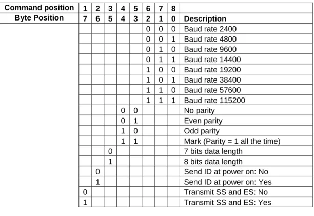
Switch A, Table 4-1, is primarily used to define the communication settings. The default for Switch A is:
11100010 9600, no parity, 8 bits, send ID at power on, transmit SS & ES
Table 4-1. Switch A Command position 1 2 3 4 5 6 7 8
Byte Position 7 6 5 4 3 2 1 0 Description 0 0 0 Baud rate 2400 0 0 1 Baud rate 4800 0 1 0 Baud rate 9600 0 1 1 Baud rate 14400 1 0 0 Baud rate 19200 1 0 1 Baud rate 38400 1 1 0 Baud rate 57600 1 1 1 Baud rate 115200 0 0 No parity 0 1 Even parity 1 0 Odd parity
1 1 Mark (Parity = 1 all the time) 0 7 bits data length
1 8 bits data length 0 Send ID at power on: No 1 Send ID at power on: Yes 0 Transmit SS and ES: No 1 Transmit SS and ES: Yes
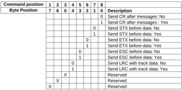
Section 4. Properties and Commands Switch B
Switch B, Table 4-2, is used to define the bracketing characters that are used in the messages. The default for Switch B is:
00000001 Send CR after messages but don’t send STX, ETX, ESC, LRC
Table 4-2. Switch B Command position 1 2 3 4 5 6 7 8
Byte Position 7 6 5 4 3 2 1 0 Description
0 Send CR after messages: No 1 Send CR after messages : Yes 0 Send STX before data: No 1 Send STX before data: Yes 0 Send ETX before data: No 1 Send ETX before data: Yes 0 Send ESC before data: No 1 Send ESC before data: Yes 0 Send LRC with track data: No 1 Send LRC with track data: Yes
X Reserved
X Reserved
Switch C
Switch C, Table 4-3, is used to define the way a card is read. The default for Switch C is: 01010101 Enable (but don’t require) tracks 1, 2 & 3; decode all types of tracks
Table 4-3. Switch C Command position 1 2 3 4 5 6 7 8
Byte Position 7 6 5 4 3 2 1 0 Description 0 0 Track 1 Disabled 0 1 Track 1 Enabled 1 1 Track 1 is required* 0 0 Track 2 Disabled 0 1 Track 2 Enabled 1 1 Track 2 is required* 0 0 Track 3 Disabled 0 1 Track 3 Enabled 1 1 Track 3 is required*
0 Decode ISO/ABA tracks only 1 Decode ISO/ABA & custom tracks
X Reserved
* If a track is required but does not exist, the Reader will indicate an error for that track.
Sentinel Definitions
The start and end sentinels values can individually be specified by commands. The default settings are shown in the Table 4-4.
Note
Changing the value of any of the sentinels does not actually change the encoded value on the magnetic track; it merely represents the sentinel in a unique way to help distinguish differently formatted tracks.
Section 4. Properties and Commands
As with the switch settings, the sentinel parameters can be discovered by sending the
corresponding command for that value immediately followed by a CR. For instance, in order to determine the present setting of the 7-bit track 3 start sentinel, send the following command:
<ESC>S5<CR>
The Reader will respond with the value, in nibbles:
<ACK><ESC>S526<CR>
Any ASCII character from 0x00 to 0x7F can be used as a sentinel. To change the value of the 7-bit track 3 start sentinel to “!” (0x21), send the following command:
<ESC>S521<CR>
Again, as with the switch commands described above, send the Upload (UP) command followed by the Reset (RS) command to complete the transaction.