This report is for the exclusive use of Intertek's Client and is provided pursuant to the agreement between Intertek and its Client. Intertek's responsibility and liability are limited to the terms and conditions of the agreement. Intertek assumes no liability to any party, other than to the Client in accordance with the agreement, for any loss, expense or damage occasioned by the use of this report. Only the Client is authorized to copy or distribute this report and then only in its entirety. Any use of the Intertek name or one of its marks for the sale or advertisement of the tested material, product or service must first be approved in writing by Intertek. The observations and test results in this report are relevant only to the sample tested. This report by itself does not imply that the material, product, or service is or has ever been under an Intertek certification program.
9/8/2011
9/8/2011
AMENDED FINAL REPORT FOR:
CUSTOMER NAME: Leviton Manufacturing Co.
417 Stone Drive St. Charles, IL 60174
PRODUCT NAME: 24 Fiber 40G 3x8 Adaptors OM3 Link
System and 24 Fiber 40G 3x8 Adaptors OM4 Link System
Tested To: IEEE 802.3ba-2010
IEEE Standard for Information technology-- Local and metropolitan area networks-- Specific requirements-- Part 3: CSMA/CD Access Method and Physical Layer Specifications Amendment 4: Media Access Control Parameters, Physical Layers, and
Management Parameters for 40 Gb/s and 100 Gb/s Operation, June 2010 Date: September 8, 2011
Project: G100443577 Report: 100443577LEX-003.1
Responsible Engineer: _______________________________Date:______________
Paul Alt, Senior Project Engineer
Approved By: ______________________________________Date:______________ Richard Proctor, Operations Manager
TABLE OF CONTENTS
Page
Declaration of Compliance...3
Sample Condition and Receive Date ... 3
1 IEEE 802.3ba-2010, IEEE Standard for Information technology-- Local and metropolitan area networks-- Specific requirements...4
1.1 Part 3: CSMA/CD Access Method and Physical Layer Specifications Amendment 4: Media Access Control Parameters, Physical Layers, and Management Parameters for 40 Gb/s and 100 Gb/s Operation ... 4
References: ...16
LIST OF TABLES Page Table 1: History of Revision ...2
Table 2: IEEE 802.3ba Amendment 4: Media Access Control Parameters, Physical Layers, and Management Parameters for 40 Gb/s and 100 Gb/s Operation - Table 86-13 - Fiber Optic Cabling Channel Characteristics at 850 nm...4
Table 3: 24 Fiber 40G 3x8 Adaptors OM3 Link System Part Numbers and Quantities...6
Table 4: 24 Fiber 40G 3x8 Adaptors OM4 Link System Part Numbers and Quantities...7
Table 5: Insertion Loss Forward Reading at 850 nm ...9
Table 6: Insertion Loss Reverse Reading at 850 nm...10
Table 7: Insertion Loss Average Reading at 850 nm ...11
Table 8: Insertion Loss Forward Reading at 850 nm ...12
Table 9: Insertion Loss Reverse Reading at 850 nm...13
Table 10: Insertion Loss Average Reading at 850 nm ...14
LIST OF FIGURES Page Figure 1: Cable Link Channel Testing Configuration...6
Figure 2: Manufacturer’s 24 Fiber 40G 3x8 Adaptors OM3 Link System Diagram ...6
Figure 3: 24 Fiber 40G 3x8 Adaptors OM3 Link System Test Setup...15
Figure 4: 24 Fiber 40G 3x8 Adaptors OM4 Link System Test Setup...15
Table 1: History of Revision
Revision Date Section # Description of Revision
Original August 30, 2011 All Original Document Issued
Declaration of Compliance
The 24 Fiber 40G 3x8 Adaptors OM3 Link System and 24 Fiber 40G 3x8 Adaptors OM4 Link System were evaluated and found to be compliant with all applicable criteria of channel
insertion loss testing for IEEE 802.3ba-2010, IEEE Standard for Information technology-- Local and metropolitan area networks-- Specific requirements-- Part 3: CSMA/CD Access Method and Physical Layer Specifications Amendment 4: Media Access Control Parameters, Physical
Layers, and Management Parameters for 40 Gb/s and 100 Gb/s Operation, June 2010.
Sample Condition and Receive Date
Leviton Manufacturing Co. selected and provided the test samples for evaluation to the criteria of IEEE 802.3ba-2010, IEEE Standard for Information technology-- Local and metropolitan area networks-- Specific requirements-- Part 3: CSMA/CD Access Method and Physical Layer
Specifications Amendment 4: Media Access Control Parameters, Physical Layers, and
Management Parameters for 40 Gb/s and 100 Gb/s Operation, June 2010. The equipment tested was the 24 Fiber 40G 3x8 Adaptors OM3 Link System and 24 Fiber 40G 3x8 Adaptors OM4 Link System; the new and unused samples were tested by Leviton and witnessed by Intertek on 8/15/2011.
1
IEEE 802.3ba-2010, IEEE Standard for Information technology-- Local and metropolitan area networks-- Specific requirements1.1 Part 3: CSMA/CD Access Method and Physical Layer Specifications Amendment
4: Media Access Control Parameters, Physical Layers, and Management Parameters for 40 Gb/s and 100 Gb/s Operation
1.1.1 Channel Insertion Loss Testing
1.1.1.1 Conformance Criteria
The cable link system channel shall not exhibit a change greater than the value stated in Table 2 below for the Multi-Mode test condition and the corresponding product type evaluation.
a. For this evaluation, the criteria is for an Ethernet 40GBASE-SR4 and 100GBASE-SX system measured at 850 nm laser-optimized 50/125 µm TIA 492AAAC (OM3) having a maximum channel value of 1.9 dB as indicated by the matching values in Table 2.
b. For this evaluation, the criteria is for an Ethernet 40GBASE-SR4 and 100GBASE-SX system measured at 850 nm laser-optimized 50/125 µm TIA 492AAAD (OM4) having a maximum channel value of 1.5 dB as indicated by the matching values in Table 2.
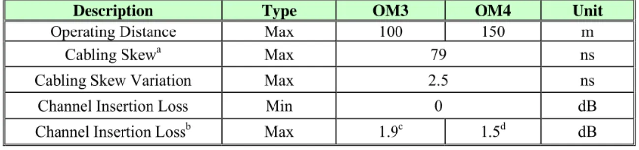
Table 2: IEEE 802.3ba Amendment 4: Media Access Control Parameters, Physical Layers, and Management Parameters for 40 Gb/s and 100 Gb/s Operation - Table 86-13 - Fiber
Optic Cabling Channel Characteristics at 850 nm.
Description Type OM3 OM4 Unit
Operating Distance Max 100 150 m
Cabling Skewa Max 79 ns
Cabling Skew Variation Max 2.5 ns
Channel Insertion Loss Min 0 dB
Channel Insertion Lossb Max 1.9c 1.5d dB
a An additional 300 ps of Skew Variation could be caused by wavelength changes, which are attributable to the
transmitter, not the channel.
b These channel insertion loss values include cable, connectors and splices. c 1.5 dB allocated for connection and splice loss.
1.1.1.2 Sample Size
One 24 Fiber 40G 3x8 Adaptors OM3 Link System and one 24 Fiber 40G 3x8 Adaptors OM4 Link System were tested for compliance to IEEE 802.3ba-2010, IEEE Standard for Information technology-- Local and metropolitan area networks-- Specific requirements-- Part 3: CSMA/CD Access Method and Physical Layer Specifications Amendment 4: Media Access Control Parameters, Physical Layers, and Management Parameters for 40 Gb/s and 100 Gb/s Operation.
1.1.1.3 Test Method
1. The test methodology used was the Leviton Manufacturing Co. internal
qualification document FBFMM127, Revision A, dated 2/23/2011 titled Insertion Loss and Continuity Testing Instructions on the 24 Channel MM OptoTest Power Meter.
2. These instructions were reviewed prior to the start of testing and found to be sufficient to the required channel loss testing as detailed in IEEE 802.3ba-2010, IEEE Standard for Information technology-- Local and metropolitan area networks-- Specific requirementsnetworks--networks-- Part 3: CSMA/CD Access Method and Physical Layer Specifications Amendment 4: Media Access Control Parameters, Physical Layers, and Management Parameters for 40 Gb/s and 100 Gb/s Operation, June 2010. 3. Prior to the beginning of testing, the Intertek witness representative reviewed the
training records of all employees involved to determine that the manufacturer had kept detailed training records of testing qualifications.
4. The testing was conducted per the FBFMM127, Revision A, dated 2/23/2011 titled Insertion Loss and Continuity Testing Instructions on the 24 Channel MM OptoTest Power Meter and the results were recorded.
5. The data was reviewed by the Intertek witness representative and found to be compliant with all applicable criteria.
6. The loss for each channel, as well as the measurement direction the loss was calculated in, was reported individually in the Test Results section of this report.
1.1.1.4 Test Configurations and Conditions
The test was conducted at lab ambient atmospheric conditions; 23 2C, ~75% RH. Optical measurements were taken at 850 nm.
The test measurement configuration is demonstrated in Figure 1.
The customer’s OM3 equipment configuration is demonstrated in Figure 2 and the individual part identification numbers are listed in Table 3.
The customer’s OM4 equipment configuration is demonstrated in Figure 2 and the individual part identification numbers are listed in Table 4.
Figure 1: Cable Link Channel Testing Configuration
Figure 2: Manufacturer’s 24 Fiber 40G 3x8 Adaptors OM3 Link System Diagram
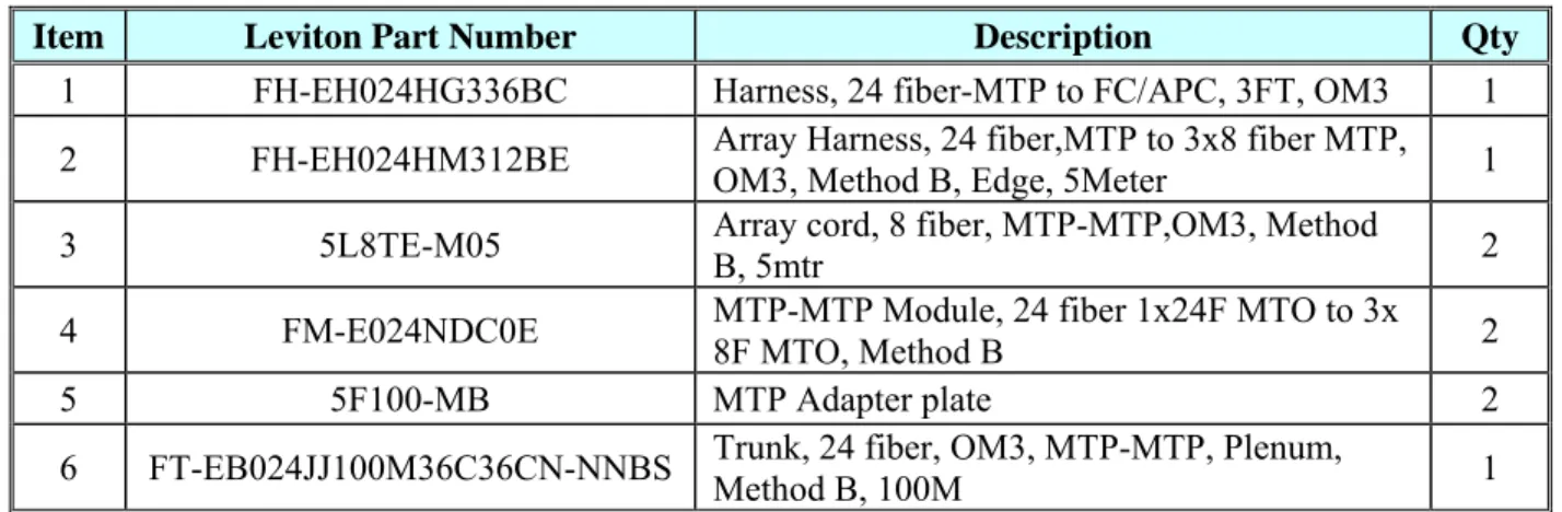
Table 3: 24 Fiber 40G 3x8 Adaptors OM3 Link System Part Numbers and Quantities
Item Leviton Part Number Description Qty
1 FH-EH024HG336BC Harness, 24 fiber-MTP to FC/APC, 3FT, OM3 1
2 FH-EH024HM312BE Array Harness, 24 fiber,MTP to 3x8 fiber MTP, OM3, Method B, Edge, 5Meter 1
3 5L8TE-M05 Array cord, 8 fiber, MTP-MTP,OM3, Method B, 5mtr 2
4 FM-E024NDC0E MTP-MTP Module, 24 fiber 1x24F MTO to 3x 8F MTO, Method B 2
5 5F100-MB MTP Adapter plate 2
6 FT-EB024JJ100M36C36CN-NNBS Trunk, 24 fiber, OM3, MTP-MTP, Plenum,
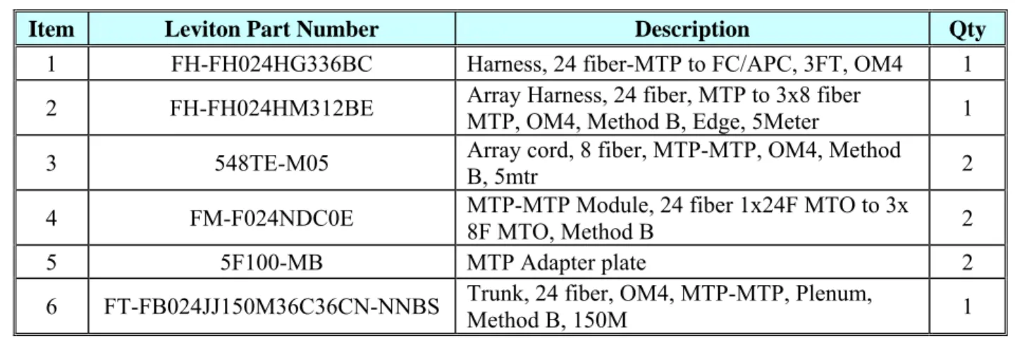
Table 4: 24 Fiber 40G 3x8 Adaptors OM4 Link System Part Numbers and Quantities
Item Leviton Part Number Description Qty
1 FH-FH024HG336BC Harness, 24 fiber-MTP to FC/APC, 3FT, OM4 1
2 FH-FH024HM312BE Array Harness, 24 fiber, MTP to 3x8 fiber
MTP, OM4, Method B, Edge, 5Meter 1
3 548TE-M05 Array cord, 8 fiber, MTP-MTP, OM4, Method
B, 5mtr 2
4 FM-F024NDC0E MTP-MTP Module, 24 fiber 1x24F MTO to 3x 8F MTO, Method B 2
5 5F100-MB MTP Adapter plate 2
6 FT-FB024JJ150M36C36CN-NNBS Trunk, 24 fiber, OM4, MTP-MTP, Plenum,
Method B, 150M 1
1.1.1.5 Test Equipment
Channel Insertion Loss Testing
Equipment Type Manufacturer Model
Number
Last Cal Date
Next Cal Date
Fiber Optic Cleaning Reels CLETOP Type A NA NA
850 nm Light Source OptoTest OP930-MM-SW24-85/13 NA NA
Power Meter with S-RHIS Detector Head OptoTest OP710-R-S 11/30/2010 11/30/2011
Optical Fiber Multi Mode 50/125 µm Jacketed
Cable (Launch Lead) Leviton NA NA NA
Mandrel Wrap Leviton NA NA NA
Computer with Measurement Software Leviton NA NA NA
1.1.1.6 Summary of Test Results Conformance/Nonconformance
Criteria Conforms?
C/NC
Ethernet 40GBASE-SR4 and 100GBASE-SX system measured at 850 nm laser-optimized 50/125 µm TIA 492AAAC (OM3) having a maximum channel
value of 1.9 dB C
Ethernet 40GBASE-SR4 and 100GBASE-SX system measured at 850 nm laser-optimized 50/125 µm TIA 492AAAD (OM4) having a maximum channel
value of 1.5 dB as indicated by the matching values in Table 2. C
Actual Sample Size and Test Method Deviations
One 24 Fiber 40G 3x8 Adaptors OM3 Link System and one 24 Fiber 40G 3x8 Adaptors OM4 Link System were tested for compliance to this section. There were no deviations from, additions to, or exclusions from, the documented test method here.
Failure History
There was no history of failure for the testing in this section.
Disposition of Nonconformance
Test Data
Table 5: Insertion Loss Forward Reading at 850 nm
Test Witnessed By: Test Date
Paul Alt 8/15/2011 OM3 Channel OM3 Configuration Directional Reading Max Value (dB) Loss Criteria Complies? Y/N 1 Forward -0.71 ≤ 1.90 dB Y 2 Forward -0.80 ≤ 1.90 dB Y 3 Forward -0.90 ≤ 1.90 dB Y 4 Forward -0.88 ≤ 1.90 dB Y 5 Forward -0.98 ≤ 1.90 dB Y 6 Forward -0.83 ≤ 1.90 dB Y 7 Forward -0.71 ≤ 1.90 dB Y 8 Forward -0.88 ≤ 1.90 dB Y 9 Forward -0.73 ≤ 1.90 dB Y 10 Forward -0.59 ≤ 1.90 dB Y 11 Forward -0.73 ≤ 1.90 dB Y 12 Forward -0.83 ≤ 1.90 dB Y 13 Forward -1.01 ≤ 1.90 dB Y 14 Forward -0.78 ≤ 1.90 dB Y 15 Forward -0.80 ≤ 1.90 dB Y 16 Forward -0.90 ≤ 1.90 dB Y 17 Forward -1.00 ≤ 1.90 dB Y 18 Forward -0.80 ≤ 1.90 dB Y 19 Forward -1.10 ≤ 1.90 dB Y 20 Forward -0.74 ≤ 1.90 dB Y 21 Forward -1.09 ≤ 1.90 dB Y 22 Forward -0.70 ≤ 1.90 dB Y 23 Forward -0.71 ≤ 1.90 dB Y 24 24 Fiber 40G 3x8 Adaptors OM3 Link System Forward -0.99 ≤ 1.90 dB Y
Table 6: Insertion Loss Reverse Reading at 850 nm
Test Witnessed By: Test Date
Paul Alt 8/15/2011 OM3 Channel OM3 Configuration Directional Reading Max Value (dB) Loss Criteria Complies? Y/N 1 Reverse -0.80 ≤ 1.90 dB Y 2 Reverse -0.91 ≤ 1.90 dB Y 3 Reverse -0.93 ≤ 1.90 dB Y 4 Reverse -0.93 ≤ 1.90 dB Y 5 Reverse -1.06 ≤ 1.90 dB Y 6 Reverse -0.86 ≤ 1.90 dB Y 7 Reverse -0.78 ≤ 1.90 dB Y 8 Reverse -0.91 ≤ 1.90 dB Y 9 Reverse -0.86 ≤ 1.90 dB Y 10 Reverse -0.75 ≤ 1.90 dB Y 11 Reverse -0.83 ≤ 1.90 dB Y 12 Reverse -0.84 ≤ 1.90 dB Y 13 Reverse -0.96 ≤ 1.90 dB Y 14 Reverse -0.62 ≤ 1.90 dB Y 15 Reverse -0.61 ≤ 1.90 dB Y 16 Reverse -0.81 ≤ 1.90 dB Y 17 Reverse -0.95 ≤ 1.90 dB Y 18 Reverse -0.72 ≤ 1.90 dB Y 19 Reverse -0.76 ≤ 1.90 dB Y 20 Reverse -0.95 ≤ 1.90 dB Y 21 Reverse -0.73 ≤ 1.90 dB Y 22 Reverse -0.93 ≤ 1.90 dB Y 23 Reverse -0.74 ≤ 1.90 dB Y 24 24 Fiber 40G 3x8 Adaptors OM3 Link System Reverse -1.02 ≤ 1.90 dB Y
Table 7: Insertion Loss Average Reading at 850 nm
Test Witnessed By: Test Date
Paul Alt 8/15/2011 OM3 Channel OM3 Configuration Directional Reading Max Value (dB) Loss Criteria Complies? Y/N 1 Average -0.76 ≤ 1.90 dB Y 2 Average -0.86 ≤ 1.90 dB Y 3 Average -0.92 ≤ 1.90 dB Y 4 Average -0.91 ≤ 1.90 dB Y 5 Average -1.02 ≤ 1.90 dB Y 6 Average -0.85 ≤ 1.90 dB Y 7 Average -0.75 ≤ 1.90 dB Y 8 Average -0.90 ≤ 1.90 dB Y 9 Average -0.80 ≤ 1.90 dB Y 10 Average -0.67 ≤ 1.90 dB Y 11 Average -0.78 ≤ 1.90 dB Y 12 Average -0.84 ≤ 1.90 dB Y 13 Average -0.99 ≤ 1.90 dB Y 14 Average -0.70 ≤ 1.90 dB Y 15 Average -0.71 ≤ 1.90 dB Y 16 Average -0.86 ≤ 1.90 dB Y 17 Average -0.98 ≤ 1.90 dB Y 18 Average -0.76 ≤ 1.90 dB Y 19 Average -0.93 ≤ 1.90 dB Y 20 Average -0.85 ≤ 1.90 dB Y 21 Average -0.91 ≤ 1.90 dB Y 22 Average -0.82 ≤ 1.90 dB Y 23 Average -0.73 ≤ 1.90 dB Y 24 24 Fiber 40G 3x8 Adaptors OM3 Link System Average -1.01 ≤ 1.90 dB Y
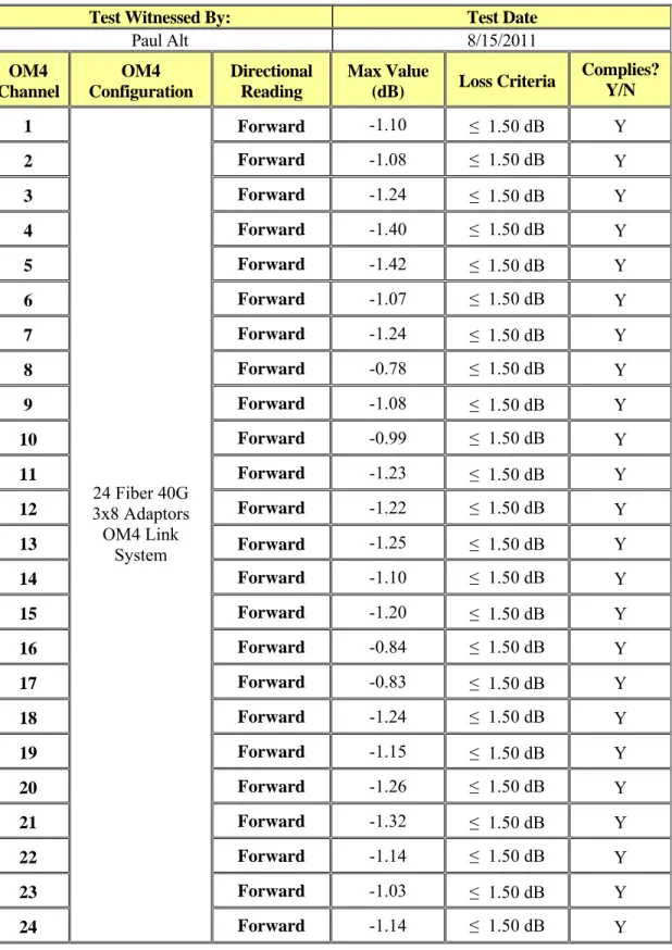
Table 8: Insertion Loss Forward Reading at 850 nm
Test Witnessed By: Test Date
Paul Alt 8/15/2011 OM4 Channel OM4 Configuration Directional Reading Max Value (dB) Loss Criteria Complies? Y/N 1 Forward -1.10 ≤ 1.50 dB Y 2 Forward -1.08 ≤ 1.50 dB Y 3 Forward -1.24 ≤ 1.50 dB Y 4 Forward -1.40 ≤ 1.50 dB Y 5 Forward -1.42 ≤ 1.50 dB Y 6 Forward -1.07 ≤ 1.50 dB Y 7 Forward -1.24 ≤ 1.50 dB Y 8 Forward -0.78 ≤ 1.50 dB Y 9 Forward -1.08 ≤ 1.50 dB Y 10 Forward -0.99 ≤ 1.50 dB Y 11 Forward -1.23 ≤ 1.50 dB Y 12 Forward -1.22 ≤ 1.50 dB Y 13 Forward -1.25 ≤ 1.50 dB Y 14 Forward -1.10 ≤ 1.50 dB Y 15 Forward -1.20 ≤ 1.50 dB Y 16 Forward -0.84 ≤ 1.50 dB Y 17 Forward -0.83 ≤ 1.50 dB Y 18 Forward -1.24 ≤ 1.50 dB Y 19 Forward -1.15 ≤ 1.50 dB Y 20 Forward -1.26 ≤ 1.50 dB Y 21 Forward -1.32 ≤ 1.50 dB Y 22 Forward -1.14 ≤ 1.50 dB Y 23 Forward -1.03 ≤ 1.50 dB Y 24 24 Fiber 40G 3x8 Adaptors OM4 Link System Forward -1.14 ≤ 1.50 dB Y
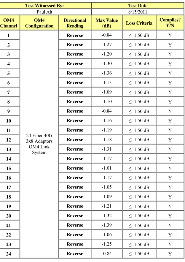
Table 9: Insertion Loss Reverse Reading at 850 nm
Test Witnessed By: Test Date
Paul Alt 8/15/2011 OM4 Channel OM4 Configuration Directional Reading Max Value (dB) Loss Criteria Complies? Y/N 1 Reverse -0.84 ≤ 1.50 dB Y 2 Reverse -1.27 ≤ 1.50 dB Y 3 Reverse -1.20 ≤ 1.50 dB Y 4 Reverse -1.30 ≤ 1.50 dB Y 5 Reverse -1.36 ≤ 1.50 dB Y 6 Reverse -1.13 ≤ 1.50 dB Y 7 Reverse -1.09 ≤ 1.50 dB Y 8 Reverse -1.10 ≤ 1.50 dB Y 9 Reverse -0.84 ≤ 1.50 dB Y 10 Reverse -1.16 ≤ 1.50 dB Y 11 Reverse -1.19 ≤ 1.50 dB Y 12 Reverse -1.18 ≤ 1.50 dB Y 13 Reverse -1.31 ≤ 1.50 dB Y 14 Reverse -1.17 ≤ 1.50 dB Y 15 Reverse -1.01 ≤ 1.50 dB Y 16 Reverse -1.17 ≤ 1.50 dB Y 17 Reverse -1.05 ≤ 1.50 dB Y 18 Reverse -1.09 ≤ 1.50 dB Y 19 Reverse -1.21 ≤ 1.50 dB Y 20 Reverse -1.32 ≤ 1.50 dB Y 21 Reverse -1.39 ≤ 1.50 dB Y 22 Reverse -1.06 ≤ 1.50 dB Y 23 Reverse -1.25 ≤ 1.50 dB Y 24 24 Fiber 40G 3x8 Adaptors OM4 Link System Reverse -0.84 ≤ 1.50 dB Y
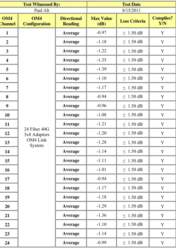
Table 10: Insertion Loss Average Reading at 850 nm
Test Witnessed By: Test Date
Paul Alt 8/15/2011 OM4 Channel OM4 Configuration Directional Reading Max Value (dB) Loss Criteria Complies? Y/N 1 Average -0.97 ≤ 1.50 dB Y 2 Average -1.18 ≤ 1.50 dB Y 3 Average -1.22 ≤ 1.50 dB Y 4 Average -1.35 ≤ 1.50 dB Y 5 Average -1.39 ≤ 1.50 dB Y 6 Average -1.10 ≤ 1.50 dB Y 7 Average -1.17 ≤ 1.50 dB Y 8 Average -0.94 ≤ 1.50 dB Y 9 Average -0.96 ≤ 1.50 dB Y 10 Average -1.08 ≤ 1.50 dB Y 11 Average -1.21 ≤ 1.50 dB Y 12 Average -1.20 ≤ 1.50 dB Y 13 Average -1.28 ≤ 1.50 dB Y 14 Average -1.14 ≤ 1.50 dB Y 15 Average -1.11 ≤ 1.50 dB Y 16 Average -1.01 ≤ 1.50 dB Y 17 Average -0.94 ≤ 1.50 dB Y 18 Average -1.17 ≤ 1.50 dB Y 19 Average -1.18 ≤ 1.50 dB Y 20 Average -1.29 ≤ 1.50 dB Y 21 Average -1.36 ≤ 1.50 dB Y 22 Average -1.10 ≤ 1.50 dB Y 23 Average -1.14 ≤ 1.50 dB Y 24 24 Fiber 40G 3x8 Adaptors OM4 Link System Average -0.99 ≤ 1.50 dB Y
Photographs:
Figure 3: 24 Fiber 40G 3x8 Adaptors OM3 Link System Test Setup
References:
External Reference Documents
ANSI Z136.2 ANS For Safe Use Of Optical Fiber Communication Systems Utilizing Laser Diode And LED Sources
ANSI/TIA-568-C.0 General Telecommunications Cabling for Customer Premises
ANSI/TIA-568-C.1 Commercial Building Telecommunications Cabling Standard
ANSI/TIA-568-C.2 Balanced Twisted-Pair Telecommunications Cabling and Components Standard
ANSI/TIA-604-3 Fiber Optic Connector Intermateability Standard, Type SC and SC-APC
ANSI/TIA-604-5 Fiber optic Intermateability Standard, Type MPO
IEEE C2-2007, National Electrical Safety Code® (NESC®)
IEEE 802.3-2005, Carrier Sense Multiple Access with Collision Detection (CSMA/CD) Access Method and Physical Layer Specifications
IEEE 802.3ba-2010, IEEE Standard for Information technology-- Local and metropolitan area networks-- Specific requirements-- Part 3: CSMA/CD Access Method and Physical Layer Specifications Amendment 4: Media Access Control Parameters, Physical Layers, and Management Parameters for 40 Gb/s and 100 Gb/s Operation
IEC 61918-2007, Industrial Communication Networks - Installation of Communication Networks in Industrial Premises
NFPA 70, National Electrical Code®
TIA-492AAAA, Detail Specification For 62.5-μm Core Diameter/125-μm Cladding Diameter Class IA Graded-Index Multimode Optical Fibers
TIA-492AAAB, Detail Specification For 50-μm Core Diameter/125-μm Cladding Diameter Class IA Graded-Index Multimode Optical Fibers
TIA-492AAAC, Detail Specification For 850-nm Laser-Optimized, 50-μm Core
Diameter/125-μm Cladding Diameter Class IA Graded-Index Multimode Optical Fibers
TIA-492AAAD, Detail Specification For 850-nm Laser-Optimized, 50 µm Core
Diameter/125 µm Cladding Diameter Class IA Graded-Index Multimode Optical Fibers of OM4 Performance
TIA-492CAAA, Detail Specification For Class IVA Dispersion-Unshifted Single-Mode Optical Fibers
TIA-492CAAB, Detail Specification For Class IVA Dispersion-Unshifted Single-Mode Optical Fibers With Low Water Peak
TIA TSB-31-C, Telephone Terminal Equipment Rationale and Measurement Guidelines for US Network Protection 51