Model 54e pH/ORP
pH/ORP HART
®
Analyzer/Controller
READ THIS PAGE BEFORE PROCEEDING! Rosemount Analytical designs, manufactures, and tests its products to meet many national and international stan-dards. Because these instruments are sophisticated techni-cal products, you must properly install, use, and maintain them to ensure they continue to operate within their normal specifications. The following instructions must be adhered to and integrated into your safety program when installing, using, and maintaining Rosemount Analytical products. Failure to follow the proper instructions may cause any one of the following situations to occur: Loss of life; personal injury; property damage; damage to this instrument; and warranty invalidation.
• Read all instructions prior to installing, operating, and servicing the product. If this Instruction Manual is not the correct manual, telephone 1-800-654-7768 and the requested manual will be provided. Save this Instruction Manual for future reference.
• If you do not understand any of the instructions, contact your Rosemount representative for clarification.
• Follow all warnings, cautions, and instructions marked on and supplied with the product.
• Inform and educate your personnel in the proper installa-tion, operainstalla-tion, and maintenance of the product. • Install your equipment as specified in the Installation
Instructions of the appropriate Instruction Manual and per applicable local and national codes. Connect all products to the proper electrical and pressure sources. • To ensure proper performance, use qualified personnel to
install, operate, update, program, and maintain the product.
• When replacement parts are required, ensure that quali-fied people use replacement parts speciquali-fied by Rosemount. Unauthorized parts and procedures can affect the product’s performance and place the safe oper-ation of your process at risk. Look alike substitutions may result in fire, electrical hazards, or improper operation. • Ensure that all equipment doors are closed and
protec-tive covers are in place, except when maintenance is being performed by qualified persons, to prevent electri-cal shock and personal injury.
Making cable connections to and servicing this instrument require access to shock hazard level voltages which can cause death or serious injury, therefore, disconnect all hazardous voltage before accessing the electronics.
Relay contacts made to separate power sources must be disconnected before servicing.
Electrical installation must be in accordance with the National Electrical Code (ANSI/NFPA-70) and/or any other applicable national or local codes.
Unused cable conduit entries must be securely sealed by non-flammable closures to provide enclosure integrity in compliance with personal safety and environmental protection require-ments. Use NEMA 4X or IP65 conduit plugs sup-plied with the instrument to maintain the ingress protection rating (IP65).
For safety and proper performance this instru-ment must be connected to a properly grounded three-wire power source.
Proper relay use and configuration is the responsibility of the user. No external connec-tion to the instrument of more than 60VDC or 43V peak allowed with the exception of power and relay terminals. Any violation will impair the safety protection provided.
Do not operate this instrument without front cover secured. Refer installation, operation and servicing to qualified personnel.
WARNING
This product is not intended for use
in the residential, commercial or
light industrial environment per
certification to EN50081-2.
Emerson Process Management
2400 Barranca Parkway Irvine, CA 92606 USA Tel: (949) 757-8500 Fax: (949) 474-7250 http://www.raihome.com
MODEL 54E PH/ORP
MICROPROCESSOR ANALYZER
TABLE OF CONTENTS
Section Title
Page
1.0 DESCRIPTION AND SPECIFICATIONS ... 1
1.1 General Description... 1
1.2 Description of Controls ... 1
1.3 Specifications... 2
1.4 Ordering Information... 4
2.0 INSTALLATION... 5
2.1 Locating the Controller ... 5
2.2 Unpacking and Inspection ... 5
2.3 Mechanical Installation ... 5
3.0 WIRING ... 7
3.1 General... 7
3.2 Power Input Wiring ... 7
3.3 Analog Output Wiring ... 7
3.4 Alarm Relay Output Wiring... 7
3.5 pH Sensor Wiring ... 9
3.6 Final Electrical Check... 12
4.0 CALIBRATION ... 14
4.1 Temperature Calibration ... 15
4.2 Automatic Two-Point Calibration ... 16
4.3 Manual Two-Point Calibration ... 18
4.4 Single-Point pH Calibration ... 19 4.5 Compensation Options ... 20 4.6 pH Slope Adjustment ... 20 4.7 Hold Mode ... 21 4.8 Trim Outputs ... 21 5.0 SOFTWARE CONFIGURATION ... 22
5.1 Changing Alarm Setpoints ... 26
5.2 Changing Output Setpoints (PID only) ... 27
5.3 Changing Output Setpoints (Normal) ... 28
5.4 Testing Outputs and Alarms ... 29
5.5 Choosing Display Options ... 31
5.6 Changing Output Parameters... 33
5.7 Changing Alarm Parameters ... 36
5.8 On-Line Diagnostics Setup... 42
Section
Title
Page
6.0 THEORY OF OPERATION ... 45
6.1 The pH Sensor Assembly... 45
6.2 Continuous Sensor Diagnostics ... 45
6.3 Interval Timer... 46
6.4 Alarm Relays ... 47
6.5 Time Proportional Control (TPC) Mode... 47
6.6 Normal Mode ... 48
6.7 Analog Outputs... 48
6.8 Controller Mode Priority... 49
6.9 PID Control ... 50
7.0 SPECIAL PROCEDURES AND FEATURES... 54
7.1 Password Protection... 54
7.2 Configuring Security ... 55
7.3 Solution Temperature Compensation ... 56
8.0 TROUBLESHOOTING ... 58
8.1 Displaying Diagnostic Variables ... 61
8.2 Troubleshooting Guidelines... 63
8.3 Replacement Parts ... 69
9.0 RETURN OF MATERIALS... 70
Appendix Title Page
A ORP CONFIGURATION... 71LIST OF TABLES
Table No. Title Page 5-1 pH Settings List ... 225-2 Standard Buffers ... 44
6-1 Controller Mode Priority Chart ... 49
8-1 Diagnostic Messages ... 59
8-2 Quick Troubleshooting Guide ... 60
8-3 Troubleshooting Guide ... 66
A-1 ORP Settings List ... 72
TABLE OF CONTENTS (CONTINUED)
TABLE OF CONTENTS (CONTINUED)
LIST OF FIGURES
Figure No. Title Page
1-1 Main Display Screen... 1
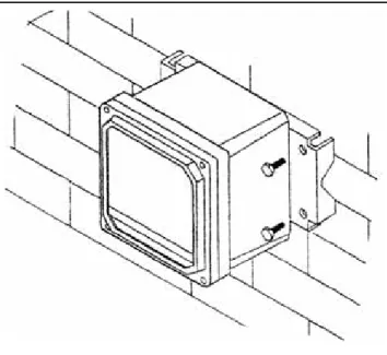
2-1 Wall Mounting ... 5
2-2 Pipe Mounting... 6
2-3 Panel Mounting... 6
3-1 Power Input and Relay Output Wiring for Model 54e pH/ORP... 8
3-2 Sensor Wiring Photo... 9
3-3 Sensor Wiring Diagram ... 10
3-4 Cable Dressing ... 11
3-5 Wiring for Sensors that have Solution Grounds ... 11
3-6 Wiring for Sensors without Solution Grounds Directly to Analyzer ... 12
3-7 Wiring for Sensors without Solution Grounds to a Junction Box ... 12
3-8 Wiring to Model 399-14 ... 13
5-1 Menu Tree ... 25
5-2 Interval Timer Examples ... 41
6-1 Time Proportional Control... 47
6-2 The Process Reaction Curve... 52
8-1 Theoretical pH vs. Millivolt Values at 25°C (77°F) ... 62
8-2 Junction Box Preamplifier Check... 65
8-3 Controller Preamplifier Check... 65
A-1 Outline of Menu Levels for ORP... 74
About This Document
This manual contains instructions for installation and operation of the Model 54epH
pH/ORP HART Analyzer/Controller. The following list provides notes concerning all
revisions of this document.
Rev. Level
Date
Notes
0 5/00 This is the initial release of the product manual. The manual has been reformatted to reflect the Emerson documentation style and updated to reflect any changes in the product offering. 0 11/01 Added trip output infor & fixed panel dimension reference. A 3/02 Updated multiple drawings & added menus.
B 7/02 Fixed setpoint example screen on page 27.
C 4/03 Updated CE info.
D 7/04 Fixed power and weight specs on page 2.
E 3/05 Updated recommended sensors on page 3.
F 4/05 Added note re ordering circuit board stack on page 69.
G 2/06 Updated Figure 1, Menu tree.
H 5/06 Noted 0-20 mA limitation for HART versions on pp. 22, 28, & 34.
SECTION 1.0
DESCRIPTION AND SPECIFICATIONS
1.1 GENERAL DESCRIPTION
The Model 54e pH/ORP analyzer/controller monitors and controls pH in chemical processes used in many industries. This manual's sections and appendices cover the system's configuration, calibration, and maintenance, and provides a troubleshooting guide. All adjustments to the current outputs, alarm relays, and calibration of the pH and temperature inputs can be made using the controller's membrane keypad.
1.2 DESCRIPTION OF CONTROLS
Figure 1-1 shows a diagram of the main display screen. Similar diagrams are used throughout this manual. The primary variable is continuously dis-played in large numerals. The process temperature and primary current output value are always dis-played on the second line of the main display screen. The third line can be configured to read several different items, as desired. In this case, it is displaying setpoints for alarms 1 and 2.
The F1-F4 keys are multifunction. The active opera-tion for that key is displayed as a label just above each function key as needed. For example, F1 is usually labeled Exit and F4 may be labeled Edit, Save, or Enter. Pressing Enter 4will access sub-menus, while pressing Edit allows changing values and Save stores the values in memory. Esc 3can be used to abort unwanted changes. Exit 1returns to the previous screen. Other labels may appear for more specialized tasks.
The up tand down bkeys are used to:
1. Move the cursor (shown in reverse video) up and down on the menu screens.
2. Scroll through the list of options available for the field shown in reverse video. When the last item of a menu has been reached, the cursor will rest on the third line of the display. If the cursor is on the second line, there are more items to see with the down arrow key.
3. Scroll through values when a highlighted numer-ical value is to be set or changed.
The right and left keys are used to move the cursor to the next digit of a number.
Green LEDs (labeled 1, 2, and 3) indicate when alarm relays 1, 2, and 3 are energized. The fourth relay indicates a fault condition. When a fault occurs, the red LED (labeled FAIL) lights up, a descriptive error message is displayed, and the action of the outputs and relays will be as described in Section 5.6 and Section 5.7 under fault value (e.g. 22 mA).
The red LED also indicates when the interval timer routine is activated and when the time limit has been reached on a feed limit timer. For more information on these subjects, see Section 5.7.
FIGURE 1-1. Main Display Screen
7.00
pH
26.2°C.
12.0 mA
1.3 SPECIFICATIONS
PHYSICAL SPECIFICATIONS - GENERAL
Enclosure:Epoxy-painted aluminum, NEMA 4X (IP65), 144 X 144 X 132 mm, DIN size (5.7 X 5.7 X 5.2 in.)
Front Panel:Membrane keyboard with tactile feedback and user selectable security. Light gray, blue and white overlay. Light gray enclosure, dark gray bezel
Display:Back-lit dot matrix LCD (7.0 x 3.5 cm), blue on gray-green. The display contrast is compensated for ambient temperature.
Process Variable Character Height:16mm (0.6 in.)
Electrical Classification:
Class I, Division 2, Groups A, B, C, & D.
T5 Ta=50°C. Dust ignition proof: Class II, Division 1, Groups E, F, & G; Class III. CSA-LR34186:
Max. relay contact rating: 28 Vdc; 110 Vac; 230 Vac; 6 amps resistive
FM: Max. relay contact rating: 28 Vdc resistive 150 mA - Groups A & B; 400 mA - Group C; 540 mA - Group D Power: Code -01: 100 - 127 VAC, 50/60 Hz ± 6%, 6.0 W 200 - 253 VAC, 50/60 Hz ± 6%, 6.0 W Code -02: 20 - 30 VDC, 6.0 W Current Outputs:
Output 1: pH, ORP, temperature, glass impedance, or reference impedance. Output 2: pH, ORP, temperature, glass impedance, or reference impedance.
Each output is galvanically isolated, 0-20 mA or4-20 mA into 500 ohms maximum load at 115/230 Vac or 24 Vdc (Code -02) or 500 ohms maximum load at 100/200 Vac. Output 1 includes digital signal 4-20 mA superimposed HART (Code -09 only).
RFI/EMI: EN-61326
LVD (Code -01 only): EN-61010-1
Ambient Temperature:0 to 50°C (32 to 122°F)
NOTE: The analyzer is operable from -20 to 60°C (-4 to 140°F) with some degradation in display performance.
Relative Humidity: 95%, non condensing
Alarms:
Relay 1 - Process, Interval*, or Time Proportional Control (code -20) Relay 2 - Process, Interval*, or Time Proportional Control (code -20) Relay 3 - Process, Interval*, or Time Proportional Control (code -20) Relay 4 - Sensor/analyzer and process fault alarm
Each relay has a dedicated LED on the front panel. *maximum of one interval timer
Relay Contacts:Relays 1-3: Epoxy sealed form A contacts, SPST, normally open Relay 4: Epoxy sealed form C, SPDT
Resistive Inductive 28 Vdc 5.0 Amps 3.0 Amps 115 Vac 5.0 Amps 3.0 Amps 230 Vac 5.0 Amps 1.5 Amps
Weight/Shipping Weight:1.8 kg/2.3 kg (4 lb/5 lb)
The Model 54e when configured as a pH analyzer, requires a dual (glass and reference) impedance pre-amplifier. This preamp converts the high impedance pH glass electrode signal to a low impedance signal. The preamplifier may be located in one of three areas: 1) in the pH sensor for best performance, 2) in a remote junction box when process temperatures exceed 80°C (176°F) in submersion applications, or 3) in the analyzer when the distance between the pH sensor and the analyzer is 4.5 meters (15 feet) or less. The Model 54e pH measures over the full range of 0-14 pH. The current output may be calibrated to repre-sent any 1 to 14 pH span.
A two-point calibration is made by immersing the sen-sor in two different buffer solutions and entering the pH values. When two buffers are used, the micro-processor automatically calculates the electrode slope which is used for self-diagnostics. The electrode slope can be read on the display and manually adjusted. A one-point process standardization is easily accom-plished by entering the pH value of a grab sample.
ANALYZER SPECIFICATIONS @ 25°C
Measurement Range:0 to 14 pH
Output Scale Expansion:Zero suppression: up to 13 pH units
Span: Any pH from 1 to 14
Accuracy:± 0.01 pH
Repeatability:± 0.01 pH
Stability:± 0.01 pH/month, non-cumulative
Temperature Coefficient:Input: ± 0.003 pH/°C Output: ± 0.006 pH/°C
Temperature Compensation :Pt 100 or Pt 1000 RTD, Automatic or Manual
–15 to 120°C (5 to 248°F)
RECOMMENDED SENSORS:
Model 320B Flow Through pHModel 320HP High Purity pH *Model 328A Steam Sterilizable pH *Model 370 and 371 EuroSenz pH
Model 381+ Insertion/Submersion/Flow Through pH *Model 389 Disposable pH
*Model 396/VP Disposable pH Model 396P/VP Disposable pH Model 396R/VP Retractable pH Model 397 Quik Disconnect pH Model 398/VP Insertion/Submersion pH *Model 398R/VP Retractable pH *Model 399 Disposable pH
*Model Hx338 Steam Sterilizable pH *Model Hx348 Steam Sterilizable pH
er, measures over a range of -1400 mV to +1400 mV in either the American convention (Oxidation
Reduction Potential), or the European convention (Reduction Oxidation-Redox). Although temperature compensation is not used for ORP measurements, the process temperature is measured and displayed. Temperature measurement is made by an RTD locat-ed in the sensor assembly.
ANALYZER SPECIFICATIONS @ 25°C
Measurement Range:–1400 to +1400 mV
Output Scale Expansion:Zero suppression: up to ±1300 mV
Span: Any ORP range from 100 to 2800 mV
Accuracy:± 1.0 mV
Repeatability:± 1.0 mV
Stability:± 1.0 mV/month, non-cumulative
Temperature Coefficient: Input:± 0.2 mV/°C Output: ± 0.4 mV/°C
Temperature Measurement:–15 to 120°C (5 to 248°F) Pt 100 or Pt 1000 RTD
RECOMMENDED SENSORS:
Model 330 Flow Through ORP *Model 371 EuroSenz ORPModel 381+ Insertion/Submersion/Flow Through ORP *Model 389 Disposable ORP
Model 396P Disposable ORP Model 396R Retractable ORP
Model 398 Insertion/Submersion ORP
Model 398VP Insertion/Submersion with VP 6.0 connector Model 398R Retractable ORP
Model 398RVP Retractable ORP with VP 6.0 connector
The Model 54e when ordered for ISE capability,
is suitable for use with a number of ion-selective elec-trodes. Consult the factory for available measure-ments and ranges.
1.4 ORDERING INFORMATION
The Model 54e pH/ORP Microprocessor Analyzeris housed in a rugged, NEMA 4X (IP65) epoxy- painted cast aluminum enclosure. Standard features include a back-lit dot-matrix liquid crystal display, sensor diagnostics, dual isolated outputs, and four relays. The analyzer can measure pH or ORP as configured by the user. For ISE capability, please consult the factory.
CODE OPTIONS
01 115/230 VAC, 50/60 Hz Power 02 24 VDC Power
MODEL
54e pH/ORP MICROPROCESSOR ANALYZER
CODE OPTIONS
09 HART Communications Protocol 20 Controller Outputs - PID and TPC
ACCESSORIES
PART NO. DESCRIPTION
2002577 Wall and two inch pipe mounting kit 23545-00 Panel mounting kit
23554-00 Cable glands, kit (Qty 5 of PG 13.5) 9240048-00 Stainless steel tag (specify marking)
5
SECTION 2.0
INSTALLATION
This section is for installation of the controller.
WARNING
All electrical installation must conform to the National Electrical Code, all state and local codes, and all plant codes and standards for electrical equipment. All electrical installations must be supervised by a qualified and respon-sible plant electrician.
2.1 LOCATING THE CONTROLLER
Position the Model 54e pH/ORP controller to minimize the effects of temperature extremes and to avoid vibration and shock. Locate the controller away from your chemical process to protect it from moisture and fumes.
Select an installation site that is more than 2 ft from high voltage conduit, has easy access for operating personnel, and is not exposed to direct sunlight.
2.2 UNPACKING AND INSPECTION
Inspect the exterior of the shipping container for any damage. Open the container and inspect the controller and related hardware for missing or damaged parts. If there is evidence of damage, notify the carrier im-mediately. If parts are missing, contact Rosemount Analytical customer support.
2.3 MECHANICAL INSTALLATION
2.3.1 Mounting the Controller
The Model 54e pH/ORP controller may be supplied with a mounting bracket accessory. If you use the mounting bracket on wall or pipe installations, avoid mounting on pipes which vibrate or are close to the process. The bracket may be modified to mount the controller on I-beams or other rigid members. You can also fabricate your own bracket or panel mount the controller using the bracket as an example.
2.3.2 Wall or Surface Mounting:
1. Mount the bracket to the controller using the sup-plied four screws as shown in Figure 2-2.
2. Mount controller mounting bracket to wall using any appropriate fastener such as screws, bolts, etc (see Figure 2-1 below).
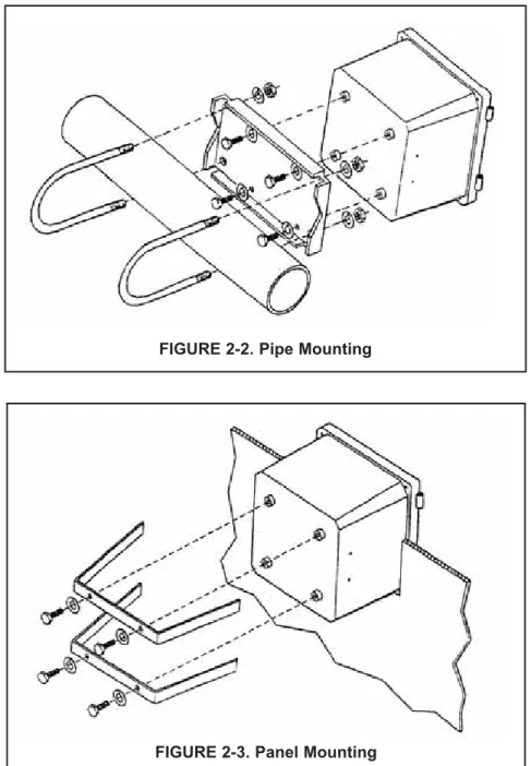
2.3.3 Pipe Mounting:
1. Attach the mounting bracket to the rear of the con-troller and tighten the four screws as shown in Figure 2-2.
2. Place supplied U bolts around the mounting pipe and through the pipe mounting bracket and mounting bracket. Tighten the U bolt nuts until the controller is securely mounted to the pipe.
FIGURE 2-2. Pipe Mounting
FIGURE 2-3. Panel Mounting 2.3.4 Panel Mounting:
The controller is designed to fit into a 5.43 x 5.43 inch (DIN standard 137.9 x137.9 mm) panel cutout (Figure 2-3). Installation requires both front and rear access.
1. Install the controller as shown in Figure 2-3. Insert the instrument enclosure through the front of the panel cutout and align the panel mounting brackets as shown.
2. Insert two mounting bracket screws through each of the two mounting brackets and into the tapped holes in the rear of the controller enclosure and tighten each screw.
3. Insert four panel mounting screws through each hole in the mounting brackets. Tighten each screw until the mounting bracket holds controller firmly in place. To avoid damaging the controller mounting brackets, do not use excessive force.
SECTION 3.0
WIRING
3.1 GENERAL
WARNING
All electrical installation must conform to the National Electrical Code, all state and local codes, and all plant codes and standards for electrical equipment. All electrical installations must be supervised by a qualified and respon-sible plant electrician.
NOTE
Wire only the analog and alarm outputs required for your application. Be sure to read the warning at the beginning of Section 2.0. The Model 54e pH/ORP has five access holes in the bot-tom of the instrument housing which accept ½-in. strain relief connectors or conduit fittings. Be sure to seal any unused access holes. As you face the front of the unit, the rear openings are for input power, and alarm relay signals. The opening on the front left is for sensor wiring only (DC). The front right is for analog output wiring.
NOTE
For best EMI/RFI protection, the output cable should be shielded and enclosed in an earth grounded, rigid, metal conduit. Connect the output cable's outer shield to the earth ground connection on TB2 (Figure 3-1)
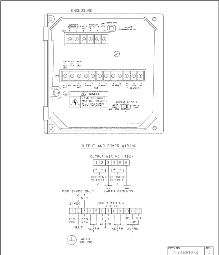
3.2 POWER INPUT WIRING
Figure 3-1 depicts the wiring detail for the Model 54e pH/ORP.Code -01: connect AC power to TB3, termi-nals 1 and 2 for 115 VAC (termitermi-nals 2 and 3 for 230 VAC). Code -02: connect DC power to TB3 terminals 1 and 2. Connect earth ground to the nearby ground lug. A good earth ground is essential for proper operation of the controller. Be sure to provide a means of discon-necting the main power to the controller.
CAUTION
Do not apply power to the controller until all electrical connections are made.
WARNING
Electrical connections to this equipment must be made in accordance with the cur-rent National and Local Electrical Codes in effect for the installation location.
3.3 ANALOG OUTPUT WIRING
The analog output wiring consists of two 4-20 mA sig-nals: output one from terminals 4 and 5, output 2 from 1 and 2 on TB2, as shown in Figure 3-1. These signals can be used for chart recorder, computer monitoring, or PID control output. The analog outputs can be pro-grammed for 4-20 mA or for 0-20 mA, direct or reverse acting. Current output 1 includes superimposed HART (code -09 only).
3.4 ALARM RELAY OUTPUT WIRING
The controller has 3 "dry" alarm relay contacts which are normally open. Alarm 1 is across terminals 4 and 5 on TB3. This alarm is typically used to control the pump in a chemical feed system. Alarm 2 across terminals 6 and 7 on TB3 is usually used to operate a light or horn as a means of alerting the chemical process operator when pH/ORP is outside the control range. Alarm 3 is across terminals 8 and 9 on TB3. All 3 of these alarms may be activated on pH/ORP or temperature. They can also be used to control other pumps or valves provided they are programmed to do so. Refer to Section 5.0 to set up these functions.
All three alarm contacts on the Model 54e pH/ORP are rated for a maximum of 3 A (1.5A, 230 VAC, inductive load). If your associated pump or valve exceeds this, use a separate contact or relay rated for the external device.
To use a contact output to control a pump, valve, or light, the contact must be wired into a circuit together with a source of power for the device to be controlled. The power can be jumpered from the main power into the controller and the circuit can be wired as shown on the wiring diagrams, Figure 3-1.
PREAMPLIFIER SELECTION
The pH sensor signal requires a preamplifier at some point in the measuring circuit. The preamp can be in-side the sensor, in the junction box, or in the controller. To allow for these options, the Model 54e pH/ORP has a jumper selectable preamp mounted on the CPU cir-cuit board (Figure 3-3). The jumper is placed in the "analyzer" position when there is no preamp in the sen-sor (or junction box). Generally, this jumper is in the "sensor" position.
FIGURE 3-1. Power Input and Relay Output Wiring for Model 54e pH/ORP
DWG. NO. REV.
pH SENSOR COMPATIBILITY
The following sensors contain solution grounds: Models 381+, 385+, 396P, 396R
The use of these sensors will allow both glass and ref-erence diagnostics.
Figure 3-3 shows how these sensors should be wired. Note that wiring connections depend on whether the sensor (or junction box) has a preamp or not. If the sensor (or j-box) has a preamp, then the preamp loca-tion jumper is moved accordingly and wiring connected as on the left of Figure 3-3. Otherwise, the jumper is moved to the "analyzer" position and wiring for TB1 is connected as on the right hand side.
Junction box (P/N 23550-00) wiring for sensors that contain a preamp is strictly point to point. All sensor leads are run to the junction box and carried through by the extension cable (P/N 9200273). Only use this rec-ommended extension cable and be careful to connect all cable leads in the junction box. Sensors without pre-amps that require cable extension should be wired up to the junction box (P/N 23555-00) as per the appropri-ate sensor instruction manual.
The following sensors do not contain solution grounds but are compatible with the Model 54e pH/ORP: Models 389-02-54, 396-54, 397-54, 399-09
Sensors without solution grounds must be wired differ-ently (see Figure 3-6). Diagnostics will only be possible on the glass electrode side of the sensor.
When extending cable, the junction box with preamp (P/N 23555-00) must be used. See Figure 3-7 for wiring details.
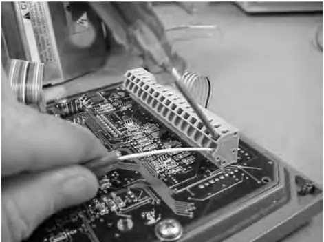
3.5 pH SENSOR WIRING
Be sure that the pH sensor has been properly installed and mounted. Wire the sensor to the junction box (if so equipped) and/or Model 54e pH/ORP according to Figures 3-5 through 3-7, or use the wiring diagram drawing included inside the controller. Use a narrow-bladed screwdriver to facilitate sensor wiring (see Figure 3-2).
The wiring diagrams show connections between the Model 54e pH/ORP and the junction box used where distance from the sensor to the controller exceeds the integral sensor cable length and inter-connecting wire is required. The interinter-connecting sensor wire recommended is P/N 9200273. Use of this cable provides EMI/RFI protection and com-plete sensor diagnostics (for sensors so equipped). The maximum interconnecting wire length is 500 ft.
IMPORTANT
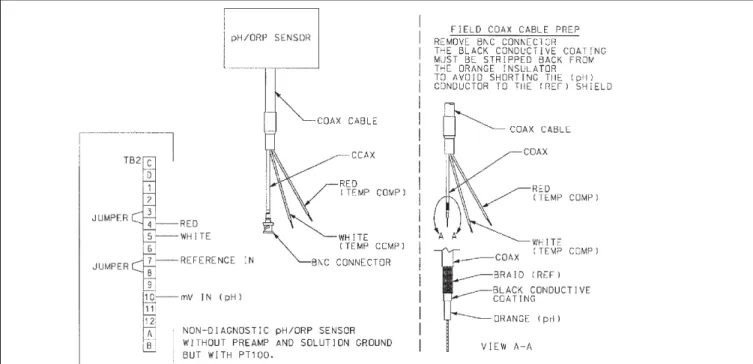
All interconnecting sensor cable ends must be properly dressed, as shown in Figure 3-4, to pre-vent the individual sensor and shield wires from shorting. All shields must be kept electrically sep-arate all the way back to the terminals on the Model 54e pH/ORP. Check that there is no continuity between the shield wires and any other sensor conductors or shields prior to connecting the sen-sor wiring to the terminals on the Model 54e pH/ORP. FAILING TO FOLLOW THESE INSTRUC-TIONS WILL RESULT IN CONTROLLER MALFUNC-TION.
FIGURE 3-3. Sensor Wiring Diagram
DWG. NO. REV.
To prepare the cable for sensor wiring:
1. Use only the cable specified. Figure 3-4 shows the 10 conductor cable with 3 shields
(9200273).
2. Strip back the PVC jacket 4 in. or far enough to access the eleven screw terminals in the junc-tion box, or the eleven terminals in the con-troller. Separate the two coaxial cables and pre-pare each as follows:
2a. Strip back the insulating black sheath about 1½ in.
2b. Separate the braid from the inner black conductive sheath.
2c. Solder an insulated wire to the braid. 2d. Strip the black conductive sheath 1 in. to
expose the colored (orange or gray) cable inside.
2e. Insulate the exposed black sheath and braid area to prevent shorts.
3. Strip ¼ in. of insulation on each conductor for terminal mounting. Insulate the exposed foil shields with heat shrink sleeves or electrical tape. Be sure that heat shrink overlaps the exposed metal end where the foil shield has been cut. Shields must not be shorted together. The sensor will not work if foil shields or drain wires are not electrically isolated from each other.
FIGURE 3-4. Cable Dressing
FIGURE 3-5. Wiring for Sensors that have Solution Grounds (Models 381+, 385+, 396P, 396R)
3.6 FINAL ELECTRICAL CHECK
When all wiring is completed, apply power to the con-troller. Observe the controller for any questionable behavior and remove power if you see a problem. With the pH sensor in the process, the display will show a pH value (though it may not be accurate).
CAUTION
To prevent unwanted chemical feed into the process and to prevent injury to operating personnel, disconnect the chemical feed pump and other external devices until the controller is checked out, programmed, and calibrated.
FIGURE 3-7. Wiring for Sensors Without Solution Grounds to a Junction Box (Models 389-02-54, 396-54, 399-09)
NOTES:
1. Interconnecting wire maximum length is 500 ft. Use PN 9200273 (no substitutes). Shields must be insulated from each other at all cable ends. Connect to junction box as shown.
2. If distance to controller is short, the junction box is not required. Connect sensor leads directly to controller.
FIGURE 3-6. Wiring for Sensors Without Solution Grounds Directly to Analyzer (Models 389-02-54, 396-54, 397-54, 399-09). For wiring to a junction box, see Figure 3-7.
SECTION 4.0
CALIBRATION
The following procedures are described in this section: • Temperature Calibration (Section 4.1)
• Auto Buffer (Two-Point) Calibration (Section 4.2) • Manual Two-Point Calibration (Section 4.3) • Single-Point pH Calibration (Section 4.4)
• Temperature Compensation Options (Section 4.5) • pH Slope Adjustment (Section 4.6)
• Hold Mode (Section 4.7)
INTRODUCTION
Calibration is the process of adjusting or standardizing the controller to a lab test (such as free acid titration) or a calibrated laboratory instrument, or standardizing to some known reference (such as a commercial pH buffer). Calibration ensures that the controller shows an accurate, and therefore, repeatable reading of pH or temperature.
Since pH measurements are affected by temperature, the Model 54e pH/ORP reads the temperature at the sensor and compensates for the changing temperature by referencing all pH measurements to 25°C (77 °F).
This compensates for temperature-related changes in the response of the glass pH electrode which would affect the pH measurement. The pH temperature com-pensation does not account for changes in chemical activity which affect the actual pH value of the solution being measured. See Section 7.0 for information on solution temperature compensation.
To ensure the controller's accuracy, it is important to perform all the calibration procedures provided in this section if you are:
• installing this unit for the first time
• changing or replacing electrodes or sensor ele-ments
• troubleshooting
IMPORTANT
Before attempting to calibrate, inspect the pH sensor assembly. It must be clean, undamaged and free from cracks or other signs of leakage or wear.
WARNINGS
Before performing any of these procedures, be sure to disable or disconnect the chemical feed pumps or other external devices (see placing controller in hold, Section 4.7)
Perform the calibration procedures in this section only in the order they are given.
4.1 TEMPERATURE CALIBRATION
This procedure is used to ensure an accurate temperature measurement by the temperature sensor. It enables the controller to display process temperature accurately as well as to compensate for the effect of tem-perature on the pH reading when the temtem-perature in your process changes. The following steps should be performed with the sensor in the process or in a grab sample near the operating temperature.
1. Check the controller temperature reading (main display) to make sure the sensor has acclimated to the process temperature. Compare the controller temperature to a calibrated temperature reading device. Proceed to the next step if the reading requires adjustment.
2. From the main display, press any key and then press Enter (F4) to access the Calibrate menu.
NOTE
The hold mode screen (top left) will appear if the hold mode was enabled in Section 5.6. Activate hold mode by pressing Edit (F4), using the arrow key to change Off to On, and then pressing Save(F4). The hold mode holds the outputs and relays in a fixed state to avoid process upsets to a control system. The message "Hold Mode Activated" will always be displayed when the con-troller is in hold. To leave the hold mode in it's current state, press Cont(F3).
Press the ê arrow key twice to bring up the screen to the left and then press Enter (F4).
NOTE
(To verify that the controller is using automatic temperature com-pensation, highlight the "Temp compensation" menu item and press Enter (F4). For more details, see Section 4.5)
3. Press Edit (F4) with this display shown to adjust the temperature. The screen below will then appear. Using the arrow keys, input the cor-rect temperature value and press Save (F4). The controller will enter the value into memory. To abort the change, press Esc (F3). Afterwards, to continue with buffer calibration, go to Section 4.2 or 4.3, otherwise press Exit (F1) three times for the main display.
NOTE
If hold mode was turned ON, be certain to install the sensor back in the process and change the setting to OFF to resume normal operation before leaving the controller. The screen on the top left will appear again before the main display is shown. Follow the same routine as in the Note for step 2 to turn the Hold Mode Off and then press Exit (F1).
7.00
pH
Hold Mode: Off
Exit Cont Edit
25.1 °C
Adjust temp: +025.1 °C
Esc SaveStandardize pH
Adjust temperature
Temp compensation
Exit Enter25.1 °C
Adjust temp: 25.1 °C
Exit Edit4.2 AUTOMATIC TWO-POINT CALIBRATION
The two-point calibration is performed when the controller is initially installed and whenever elements of the sensor assembly or controller are replaced. The two-point calibration re-establishes the slope of the elec-trode. This is necessary because the slope (mV/pH change) decreases as the glass pH electrode ages.
Buffer calibration uses measurements of two solutions to calculate the slope (efficiency) and the zero offset of the pH sensor.
Obtain two pH buffer solutions with different pH values. They should be at least 2 pH units apart. Unopened buffers have a shelf life of about a year and should generally not be reused because of possible contamina-tion.
Before taking readings, clean and rinse the sensor (if necessary). Shake the sensor down to remove air bubbles from the glass electrode tip. Place the sensor into the first buffer solution. Verify and adjust the temperature (Section 4.1), if necessary.
The controller is set at the factory for automatic calibration. If this feature has been disabled (Section 5.9), see Section 4.3 for manual calibration. Auto calibration includes automatic buffer recognition (factory set buffers are 4.01, 7.00, and 10.01 pH) and a stabilization check. The stabilization feature eliminates errors caused by changes in temperature and response time of the glass electrode. To change these settings, refer to Section 5.9.
1. From the main display, press any key to obtain the main menu. With the cursor on "Calibrate", press Enter (F4). With the cursor on "Buffer calibration", press Enter (F4) again.
NOTE
The hold mode screen (top left) will appear if the hold mode was enabled in Section 5.6. Activate hold mode by pressing Edit (F4), using the arrow key to change Off to On, and then pressing Save(F4). The hold mode holds the outputs and relays in a fixed state to avoid process upsets to a control system. To leave the hold mode in it's current state, press Cont (F3).
2. With the sensor in the first buffer, press Cont (F3). To cancel the cal-ibration, press Abort (F1).)
The word "Wait" flashes until the sensor is stabilized.
The controller is waiting for the pH reading to stabilize within the parameters established in Section 5.9. If the controller appears to be locked at this stage, the reading is not stable enough. Increase the stabilize pH and/or decrease the stabilize time and retry the calibra-tion.
Press Abort (F1) to cancel the calibration if it appears to be taking too long.
7.00
pH
Hold Mode: Off
Exit Cont Edit
4.02
pH
Buffer 1 -- “Wait”
Abort Cont4.02
pH
Autocal buffer 1
Abort ContBuffer calibration
Standardize pH
Adjust temperature
Exit Enter3. A screen like the one on the left will appear after stabilization.
Use the arrow keys to select the correct buffer.
If the correct buffer does not appear, refer to Section 5.9 and select a buffer group that includes the desired buffers. As usual, to cancel the calibration, press Abort (F1).
When the correct buffer is shown, remove the sensor from buffer 1, rinse and gently dry it. Press Cont (F3) to continue.
NOTE
The calibration calculation does not occur until buffer 2 is com-pleted. Aborting the calibration at this point will not change the reading of the controller.
4. This screen appears immediately after pressing the Cont key in step 3.
Place the sensor into the second buffer. Press Cont (F3) to proceed. The word "Wait" flashes (as before) until the sensor is stabilized. Press Abort (F1) to cancel the calibration if the process is taking too long. (see step 2).
5. A screen like the one on the left will appear after stabilization. Use the arrow keys to select the correct buffer, and press Cont (F3). If the correct buffer does not appear, refer to Section 5.9 and select a buffer group that includes the desired buffers. As usual, to cancel the calibration, press Abort (F1).
This completes the calibration. The controller has now recalculated the slope and the zero offset of the sensor.
CALIBRATION NOTES
1. A two-point calibration should always be followed by a sin-gle-point calibration (see Section 4.4).
2. After a buffer calibration, the electrode slope value can be checked to see if the electrode is aging.
3. If the sensor is not at the same temperature as the buffer the cal-ibration will be in error.
NOTE
If hold mode was turned ON, be certain to install the sensor back in the process and change the setting to OFF to resume normal operation before leaving the controller. The hold mode screen will appear again before the main display is shown. Follow the same routine as in the Note for step 1 to turn the Hold Mode Off and then press Exit (F1).
4.02
pH
Buf1 done:
4.01
@25°C
Abort Cont10.02
pH
Buf2 done:
10.01
@25°C
Abort Cont10.02
pH
Auto buffer cal done
Abort Cont
10.02
pH
Autocal buffer 2
This procedure is followed if Autocal is set to "Manual" in Section 5.9. Buffer values are entered manually and no stabilization check is used. 1. From the main display, press any key to obtain the main menu. With
the cursor on "Calibrate", press Enter (F4). With the cursor on "2-pt Calibration", press Enter (F4) again.
NOTE
The Hold Mode screen may appear if the feature was enabled in Section 5.6. Changing the Hold Mode to ON holds the outputs in a fixed state, and avoids process upsets during calibration.
2 . Place the sensing portion of the pH sensor into a beaker containing the first buffer solution. The large displayed pH shows the actual pH. 3. Allow the pH and temperature to stabilize. This may take several min-utes, as the pH sensor may need to cool down to the buffer temper-ature. The display will flash “wait’ while the reading is stabilizing. When the pH reading is stable, press Cont (F3) to update the read-ing. Press Edit (F4) and use the arrow keys to change the indicated buffer value to the correct value for the buffer at the stabilized tem-perature. The pH values at various temperatures are written on the label of most buffer bottles.
4. Press Pt 2 (F3) to enter Buffer 1 into memory and proceed to buffer 2 (pt. 2) calibration.
NOTE
Press Abort (F1) to cancel buffer calibration and return to the cal-ibration menu.
5. Remove the sensor from buffer 1 and rinse in water.
6. Place the pH sensor into a beaker containing the second buffer solu-tion.
7. Allow the pH and temperature to stabilize (as before) and press Cont (F3). The display will flash “wait’ while the reading is stabilizing. 8. Enter the correct value for buffer 2 as described in step 3 and press
Save (F4) to complete the calibration. Reinstall the sensor.
CALIBRATION NOTES
1. A two-point calibration should always be followed by a sin-gle-point calibration (see Section 4.4)
2. After a buffer calibration, the electrode slope value can be checked to see if the electrode is aging.
3. If the sensor is not at the same temperature as the buffer the cal-ibration will be in error.
4. If the hold mode is ON, be certain to reinstall the sensor in the process and change the setting to OFF to return to normal oper-ation.
4.3 MANUAL TWO-POINT CALIBRATION
2-pt calibration
Standardize pH
Adjust temperature
Exit Enter4.01
pH
Pt. 1:
04.00pH 25°C
Pt 2 Edit4.01
pH
Calibrate point 1
Abort Cont10.01
pH
Calibrate point 2
Abort Cont10.01
pH
2-pt calibration done
Esc Save4.4 SINGLE-POINT pH CALIBRATION
A single-point calibration (standardization) should always be performed following a two-point calibration. It may have to be performed as often as once a day to ensure that the sensor is accurately reading pH. As the glass electrode or the porous reference plug fouls and ages, the pH ing will drift. The single-point calibration re-establishes the exact pH read-ing. Experience with your process and it's acceptable range of pH will dic-tate how often the single-point calibration will have to be performed. The procedure is most easily performed on-line by determining the pH of a process grab sample with a laboratory instrument. This value can then be entered into the Model 54e pH/ORP to make it agree with the lab instru-ment.
Many processes have effects on on-line sensors that cause them to read slightly different than grab samples measured with laboratory electrodes. Standardizing the controller allows both readings to agree. This proce-dure does not calculate the sensor slope.
1. Take a grab sample that is as close to the sensor as possible. 2. Using a calibrated pH instrument with automatic temperature
com-pensation, determine the pH of the process or grab sample (as close to actual process temperature as possible). Continue with this pro-cedure if an adjustment is needed.
3. From the main display, press any key to obtain the main menu. With the cursor on "Calibrate", press Enter (F4).
NOTE
The Hold Mode screen may appear if the feature was enabled in section 5.6. Changing the Hold Mode to ON holds the outputs in a fixed state, and avoids process upsets during calibration. Remember to change the Hold Mode back to OFF when calibra-tion is completed.
4. Move the cursor (using the down arrow key) from "Buffer Calibration" (or 2-pt calibration) to "Standardize" and press Enter (F4).
5. The pH reading in large numbers is the live process pH reading. The next line displays the pH reading when this screen was first accessed. Press Edit (F4) to perform the standardize.
Use the arrow keys to change the second line standardize value to the correct pH and press Save (F4) to complete the procedure. Esc (F3) will cancel.
The pH reading in the large display will change to the new value and the zero offset number will be recalculated.
NOTE
Before exiting the calibration mode, remember to change the hold mode setting to OFF (if it was turned on in step 3).
Buffer calibration
Standardize
Adjust temperature
Exit Enter4.01
pH
Standardize: +07.00 pH
Esc Save7.01
pH
Standardize: 7.01 pH
Exit Enter4.5 TEMPERATURE COMPENSATION OPTIONS
4.6 pH SLOPE ADJUSTMENT
Automatic Temperature Compensation is a standard option for pH equip-ment and is used in virtually all pH measureequip-ment situations. If compen-sation is not desired, the temperature signal from the sensor can be ignored by placing the controller in the manual temperature compensa-tion mode.
Manual mode allows the input of a fixed value that will be used instead of the sensor value. The manual temperature value need only be entered if the temperature compensation setting is manual. In this case, a value may be entered between -15 and 120°C (5 and 248°F).
To change these settings, obtain the top screen by pressing Enter (F4) when Calibrate is highlighted in the main menu and then press the arrow key. Press Enter (F4) again to obtain the lower screen. Highlight the desired item and press Edit (F4) and change the value as needed. Options are Auto or Manual temperature compensation and the temper-ature values listed above. Press Save (F4) to save the change. Esc (F3) will cancel the change.
NOTE
When the temperature compensation setting is manual, all tem-perature specific faults are disabled.
The slope of the glass electrode is normally calculated during buffer cali-bration. It can, however, be entered directly (if known) using this proce-dure. A new electrode has a slope of about 59 mV/pH but as it ages the slope will decrease. A slope value below 47 mV/pH unit is a sign of an aged electrode and is not considered adequate for calibration. The pH slope can also be viewed on the diagnostic variables screen.
Use the procedure in Section 4.5 to obtain the screen to the left with "pH slope" highlighted. Press Enter (F4) to display the slope value now being used. Press Edit (F4) for editing and then change the value as needed. Save the new value with Save (F4).
Acceptable slope values are between 45.0 and 60.0 mV/pH.
NOTE
Before exiting the calibration mode, if the Hold Mode is ON, be certain to change the setting to OFF to resume normal operation.
Adjust temperature
Temp compensation
pH slope
Exit Enter
Temp comp: Auto
Manual temp:
025.0°C
Exit EnterpH slope:
59.16 mV/pH
Exit EnterTemp compensation
pH slope
Output trim
Exit Enter4.7 HOLD MODE
4.8 TRIM OUTPUTS
Placing the Controller on Hold for Maintenance. Before performing main-tenance or repair of the sensor, the Controller can be placed in hold (refer to Section 5.6 to enable this feature) to prevent process upsets while the reading is off-line. This will place the current outputs into the selected default states (see Section 5.6). The relays will act as selected in relay default, see Section 5.7.
Before removing the sensor from the process, press any key and then Enter (F4). When the hold mode has been enabled, the hold mode screen (on the left) will appear prior to calibration. To continue without putting the controller in hold, simply press Cont (F3). To put the controller in hold, press Edit (F4), use the arrow key to change the "Off" to "On" and press Save (F4).
NOTE
When the Hold Mode is activated ("On"), "Hold Mode Activated" will always appear on the bottom line of the display.
Always calibrate after cleaning or repair of the pH sensor. After installing the sensor back into the process, always change the Hold Mode setting to OFF.
The instrument’s current outputs may be calibrated (trimmed) if neces-sary. If either the power board or the CPU board is replaced, the outputs must be calibrated. To perform this procedure, a calibrated meter must be connected to the output being calibrated.
To perform an output calibration, from the main display press any key to obtain the main menu. With the cursor on “calibrate,” press Enter (F4). With the cursor on “Output trim,” press Enter (F4) again. Select “Trim out-put 1” or “Trim outout-put 2” as appropriate.
Press Edit (F4) to select Cal point 1 (4 mA expected and simulated) or Cal point 2 (20 mA expected and simulated). Adjust the Meter value to match the reading of the calibrated meter connected to the output. Press Enter (F4) to complete the calibration.
7.00
pH
Hold Mode: Off
Exit Cont Edit
7.00 pH
26.2°C
12.0mA
Hold Mode Activated
Temp compensation
pH slope
Output trim
SECTION 5.0
SOFTWARE CONFIGURATION
This section contains the following:
• An introduction to using the configuration process • A List of Settings for the controller
• Step-by-step instructions and explanations for each parameter on the List
INTRODUCTION TO CONFIGURATION
The controller arrives from the factory configured and ready to operate as a pH controller. Refer to Appendix A for ORP meas-urements.
Figure 5-1 is an outline of the menu structure. Before attempting any changes refer to the parameter setup list shown in Table 5-1. This table presents a brief description and the possible options.
The factory setting is listed with a space for the user setting. It is recommended that the list be carefully reviewed before any changes are made.
On initial configuration, it is recommended that the parameters be entered in the order shown on the worksheet. This will reduce the chance of accidentally omitting a needed parameter.
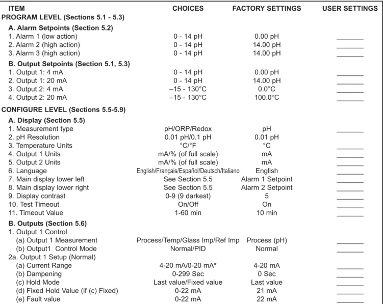
ITEM CHOICES FACTORY SETTINGS USER SETTINGS
PROGRAM LEVEL (Sections 5.1 - 5.3) A. Alarm Setpoints (Section 5.2)
1. Alarm 1 (low action) 0 - 14 pH 0.00 pH _______
2. Alarm 2 (high action) 0 - 14 pH 14.00 pH _______
3. Alarm 3 (high action) 0 - 14 pH 14.00 pH _______
B. Output Setpoints (Section 5.1, 5.3)
1. Output 1: 4 mA 0 - 14 pH 0.00 pH _______
2. Output 1: 20 mA 0 - 14 pH 14.00 pH _______
3. Output 2: 4 mA –15 - 130°C 0.0°C _______
4. Output 2: 20 mA –15 - 130°C 100.0°C _______
CONFIGURE LEVEL (Sections 5.5-5.9) A. Display (Section 5.5)
1. Measurement type pH/ORP/Redox pH _______
2. pH Resolution 0.01 pH/0.1 pH 0.01 pH
3. Temperature Units °C/°F °C _______
4. Output 1 Units mA/% (of full scale) mA _______
5. Output 2 Units mA/% (of full scale) mA _______
6. Language English/Français/Español/Deutsch/Italiano English _______ 7. Main display lower left See Section 5.5 Alarm 1 Setpoint _______ 8. Main display lower right See Section 5.5 Alarm 2 Setpoint _______
9. Display contrast 0-9 (9 darkest) 5 _______
10. Test Timeout On/Off On _______
11. Timeout Value 1-60 min 10 min _______
B. Outputs (Section 5.6) 1. Output 1 Control
(a) Output 1 Measurement Process/Temp/Glass Imp/Ref Imp Process (pH) _______
(b) Output1 Control Mode Normal/PID Normal _______
2a. Output 1 Setup (Normal)
(a) Current Range 4-20 mA/0-20 mA* 4-20 mA _______
(b) Dampening 0-299 Sec 0 Sec _______
(c) Hold Mode Last value/Fixed value Last value _______
(d) Fixed Hold Value (if (c) Fixed) 0-22 mA 21 mA _______
(e) Fault value 0-22 mA 22 mA _______
TABLE 5-1. pH Settings List
ITEM RANGES FACTORY SETTINGS USER SETTINGS 2b. Output 1 Setup (PID)
(a) Setpoint -2 to 16 pH or -15 to 130°C 7 pH _______
(b) Proportional 0-299.9% 100.0% _______
(c) Integral 0-2999 sec 0 sec _______
(d) Derivative 0-299.9% 0.0% _______
(e) LRV (4 mA) -2 to 16 pH or -15 to 130°C 2 pH _______
(f) URV (20 mA) -2 to 16 pH or -15 to 130°C 0 pH _______
3. Output 2 Control
(a) Output 2 Measurement Process/Temp/Glass Imp/Ref Imp Temperature _______
(b) Output 2 Control Mode Normal/PID Normal _______
4a. Output 2 Setup (Normal)
(a) Current Range 4-20 mA/0-20 mA 4-20 mA _______
(b) Dampening 0-255 Sec 0 Sec _______
(c) Hold Mode Last value/Fixed value Last value _______
(d) Fixed Hold Value (if (c) Fixed) 0-22 mA 21 mA _______
(e) Fault value 0-22 mA 22 mA _______
4b. Output 2 Setup (PID)
(a) Setpoint -2 to 16 pH or -15 to 130°C 7 pH _______
(b) Proportional 0-299.9% 100.0% _______
(c) Integral 0-2999 sec 0 sec _______
(d) Derivative 0-299.9% 0.0% _______
(e) LRV (4 mA) -2 to 16 pH or -15 to 130°C 2 pH _______
(f) URV (20 mA) -2 to 16 pH or -15 to 130°C 0 pH _______
5. Hold (Outputs and Relays) Disable/Enable/ 20 min timeout Disable feature _______ C. Alarms (Section 5.7)
1. Alarm 1 Control
(a) Activation Method Process/Temp Process _______
(b) Alarm 1 Control Mode Normal/TPC Normal _______
2a. Alarm 1 Setup (Normal)
(a) Configuration Low alarm/High alarm/Off Low _______
(b) Hysteresis (deadband) 0 - 5.00 pH 0.01 pH _______
(c) Delay Time 0-99 sec 0 sec _______
(d) Relay Fault Open/Closed/None None _______
2b. Alarm 1 Setup (TPC)
(a) Setpoint -2 to 16 pH or -15 to 130°C 7 pH _______
(b) Proportional 0-299.9% 100.0% _______
(c) Integral 0-2999 sec 0 sec _______
(d) Derivative 0-299.9% 0.0% _______
(e) Time Period 10-2999 sec 30 sec _______
(f) LRV (100% On) -2 to 16 pH or -15 to 130°C 2 pH _______
(g) URV (100% Off) -2 to 16 pH or -15 to 130°C 0 pH _______
(h) Relay Fault None/Open/Closed None _______
3. Alarm 2 Control
(a) Activation Method Process/Temp Process _______
(b) Alarm 2 Control Mode Normal/TPC Normal _______
4a. Alarm 2 Setup (Normal)
(a) Configuration Low alarm/High alarm/Off High _______
(b) Hysteresis (deadband) 0 - 5.00 pH 0.01 pH _______
(c) Delay Time 0-99 sec 0 sec _______
(d) Relay Fault Open/Closed/None None _______
4b. Alarm 2 Setup (TPC)
(a) Setpoint -2 to 16 pH or -15 to 130°C 7 pH _______
(b) Proportional 0-299.9% 100.0% _______
(c) Integral 0-2999 sec 0 sec _______
(d) Derivative 0-299.9% 0.0% _______
(e) Time Period 10-2999 sec 30 sec _______
(f) LRV (100% On) -2 to 16 pH or -15 to 130°C 2 pH _______
(g) URV (100% Off) -2 to 16 pH or -15 to 130°C 0 pH _______
(h) Relay Fault None/Open/Closed None _______
TABLE 5-1. pH Settings List (continued)
ITEM RANGES FACTORY SETTINGS USER SETTINGS
5. Alarm 3 Control
(a) Activation Method Process/Temp Process _______
(b) Alarm 3 Control Mode Normal/TPC Normal _______
6a. Alarm 3 Setup (Normal)
(a) Configuration Low alarm/High alarm/Off High _______
(b) Hysteresis (deadband) 0 - 5.00 pH 0.01 pH _______
(e) Delay Time 0-99 sec 0 sec _______
(d) Relay Fault Open/Closed/None None _______
6b. Alarm 3 Setup (TPC)
(a) Setpoint -2 to 16 pH or -15 to 130°C 7 pH _______
(b) Proportional 0-299.9% 100.0% _______
(c) Integral 0-2999 sec 0 sec _______
(d) Derivative 0-299.9% 0.0% _______
(e) Time Period 10-2999 sec 30 sec _______
(f) LRV (100% On) -2 to 16 pH or -15 to 130°C 2 pH _______
(g) URV (100% Off) -2 to 16 pH or -15 to 130°C 0 pH _______
(h) Relay Fault None/Open/Closed None _______
7. Alarm 4 Control
(a) Alarm Fault/Off Fault _______
8. Feed Limit Timer
(a) Feed Limit Disable/alarm 1/alarm 2/alarm 3 Disable _______
(b) Timeout Value 0-10,800 sec 3600 sec _______
C. Alarms (Section 5.7) 9. Interval Timer
(a) Timer (selection) Disable/alarm 1/alarm 2/alarm 3 Disable _______ (b) Timer (activation method) Time activated/Imped. activated Time activated _______
(c) Interval 0-999.9 hr 24.0 hr _______
(d) Repeats 1-60 1 _______
(e) On Time 0-2999 sec 120 sec _______
(f) Off Time 0-2999 sec 1 sec _______
(g) Recovery 0-999 sec 600 sec _______
D. Diagnostics (Section 5.8)
1. Diagnostics (Glass and Reference) On/Off 000 (no security) _______ 2. Glass Imp(edance) High Setpoint 0-2000 MOhms (0 disables) 000 (no security) _______ 3. Glass Imp(edance) Low Setpoint 0-900 MOhms (0 disables)
4. Ref(erence) Imp(edance) High 0-140 KOhms (0 disables) 000 (no security) _______
5. Zero Offset 0-999 mV (0 disables) 000 (no security) _______
6. Cal(ibration) Warn(ing) 0-500% (0 disables)
7. Imped(ance Temperature) Comp(ensation) On/Off 000 (no security) _______ E. Auto Calibration (Section 5.9)
1. Autocal (Buffer List Selection) Manual/Standard/DIN 19267 000 (no security) _______ 2. Stabilize pH (Auto Calibration) .01-.50 pH 000 (no security) _______ 3. Stabilization Time (Auto Calibration) 0-30 sec 000 (no security) _______ F. Security (Section 7.1)
1. Lock all 000-999 000 (no security) _______
2. Lock Program (Lock all except Calibrate) 000-999 000 (no security) _______ 3. Lock Config. (Lock all except Calibrate,
Output setpoints (PID), Simulated Tests
Alarm Setpoints, and Rerange Outputs) 000-999 000 (no security) _______ D. Solution Temperature Compensation (Section 7.3)
1. Temp(erature) Coeff(icient) -0.044 to 0.028pH/°C 000 (no security) _______ 2. Operate Iso(potential pH) -1.35 to 20.12 pH 000 (no security) _______
3. Sensor Iso(potential) 0-14 pH 000 (no security) _______
By changing the standard output configuration, you can set up the Model 54e pH/ORP to perform a wide variety of control and monitoring tasks. The configuration procedures allow you to program the controller to meet the specific control and monitoring requirements of your particular plant. This is done by recording the desired configuration parameters on the List of Settings Form and then actually configuring them by using the keys on the controller front panel.
Accessing Calibrate, Program and Configure Menus.
Operating configuration changes are made at the levels shown in Figure 5-1. Pressing any key from the main dis-play will access the main menu (top left). Refer to Appendix A for ORP measurements.
Level 1 Calibrate. To access calibration selections from the main menu, with the cursor on "Calibrate" press Enter (F4). All buffer calibration, pH standardization and tem-perature adjustments are made at this level (refer to Section 4.0 for these procedures).
Level 2 Program. To access the program level from the main menu, place the cursor over "Program" with the down arrow key. Then press Enter (F4). From the program level menu, changes can be made to the alarm setpoints and the output setpoints.
Level 3 Configure.To access the configure level from the main menu place cursor over "Program" and Enter (F4), then place cursor over "Configure" and Enter (F4). This level contains advanced selections, such as alarms, diag-nostics, autocal and others.
Blank Out 2 R1 GI In AL2 AL3
5.1 CHANGING ALARM SETPOINTS
This section describes how the three alarm setpoints can be changed. Move the cursor down by pressing the arrow key.
1. From the main menu, move the cursor down to "Program" and press Enter (F4). On the next display, with the cursor on "Alarm setpoints", press Enter (F4).
2. Select the desired alarm by moving the cursor down to highlight it. When the correct alarm is highlighted, press Enter (F4) to get to the adjustment screen.
In this example we have pressed the arrow key down once to access the alarm 2 setpoint.
NOTE
There are 2 different possible screens at the next point, depend-ing on whether the alarm has been configured as normal or TPC.
3a. (normal alarm). The setpoint now being used for this alarm and the kind of alarm (high or low) are displayed. If the alarm has been turned off, then "off" will be displayed instead of "High". The "Enter" key has now changed to the "Edit" key and will allow changing the setpoint once the F4 key has been pressed. If the setpoint is ok, then press Exit (F1).
After the Edit (F4) key is pressed, use the arrow keys to change the display to the desired setpoint and press Save (F4) to enter into memory. The plus (+) sign can be changed to a minus sign by press-ing the down arrow key when the (+) is highlighted. To abort the change, press Esc (F3) to return to the previous menu.
3b. (TPC alarm only). When the alarm has been configured as TPC, the setpoint is used for the TPC calculation of how long the alarm should stay on. The "Enter" key has now changed to the "Edit" key and will allow changing the setpoint once the F4 key has been pressed. If the setpoint is ok, then press Exit (F1).
After the F4 key is pressed, use the arrow keys to change the dis-play to the desired setpoint and press Save (F4) to enter into mem-ory. The plus + sign can be changed to a minus sign by pressing the down arrow key. To abort the change, press Esc (F3) to return to the previous menu.
Alarm setpoints
Output setpoints
Simulate tests
Exit EnterAlarm 1 setpoint
Alarm 2 setpoint
Alarm 3 setpoint
Exit EnterAlarm High: 14.00pH
Exit EnterSetpoint: 07.00 pH
Exit Edit5.2 CHANGING OUTPUT SETPOINTS (PID ONLY)
This section describes how the two output setpoints can be changed. This selection is only active if the current output control mode has been set to "PID" (see Section 5.6). If the control mode is set to "normal", then "Not applicable" will be displayed. For reranging outputs, go to Section 5.3.
1. From the main display, press any key to obtain the main menu. With the down arrow key, move the cursor to "Program" and press Enter (F4). With the cursor on "Output setpoints" (as on the left), press Enter (F4).
2. Highlight the desired Output setpoints and press Enter (F4).
3. The setpoint now being used is displayed. Press Edit (F4) and use the arrow keys to change the display to the new value.
4 mA is the deviation from setpoint that will result in a 4 mA out. 20 mA is the deviation from setpoint that will result in a 20 mA setpoint. Highlight the desired item and press Edit 4and the arrow keys to change the display to the new value.
Example: A setpoint of 6 pH with a URV of +2 and a LRV of 0.0 pH. When the pH is 7, the output will be (7 - 6)/(2 - 0) = 50% of range (12 mA). If the setpoint is changed to 6.5 pH, the output will be 7 - 6.5)/(2 - 0) = 25% of range (8 mA).
4. Press Save (F4) to enter into memory or Esc (F3) to abort the change.
The Control setpoint is typically the condition where the current output is at a minimum. The P and I control calculations use the setpoint to adjust the current output to the desired level based on the parameters estab-lished in Section 5.6.
Alarm setpoints
Output setpoints
Simulate tests
Exit EnterOutput 1 setpoints
Output 2 setpoints
Exit EnterSetpoint:
7.00 pH
4mA: 0.00 pH
20mA: 2.00 pH
Exit EnterSetpoint: + 06.90 pH
Exit Enter5.3 CHANGING OUTPUT SETPOINTS (NORMAL ONLY)
This section describes how the 4 (or 0) to 20 mA current outputs can be reranged. Note that the current outputs can be configured to represent pH, temperature, glass impedance, or reference impedance. See Section 5.6 for details on configuration.
1. From the main menu, move the cursor down to "Program" and press Enter (F4). On this display, move the cursor to "Rerange outputs" and press Enter (F4).
Note: 0-20 mA output range is disabled on output 1 with HART-enabled version (-09 option).
2. Select the desired output by moving the cursor down to highlight it. When the correct output is highlighted, press Enter (F4) to get to the adjustment screen.
3. This message asks for confirmation of the requested change. Changes in these settings may degrade process control, so use cau-tion when making changes. Press Enter (F4) to continue. Otherwise press Abort (F1).
This screen allows changing the setpoints for output 1. A similar screen is available for output 2. The live current output now being transmitted by the controller is shown on the third line.
4. Press Edit (F4) to make changes in the setpoints. The Edit key changes to a Save key and the F3 key becomes active as an Esc key. Use the arrow keys to make the display read the desired val-ues for the high and low current output limits. When done, press Save (F4) to enter the changes into memory. Press Esc (F3) to can-cel changes.
NOTE
Outputs that have been configured as 0-20 mA in Section 5.6, will show 0 mA instead of 4 mA on the top line. Outputs that are based on temperature or impedance values will show matching units such as °C, MΩ, or kΩ. See Section 5.6 for output config-uration.
Output 1
Output 2
Exit Enter4 mA: +00.00 pH
20 mA: 14.00 pH
Output 1: 12.00 mA
Esc SaveAlarm setpoints
Output setpoints
Simulated test
Exit EnterCAUTION: Current
Output 1 will be
affected.
Exit Enter4 mA: 0.00 pH
20 mA: 14.00 pH
Output 1: 12.00 mA
Exit EnterTest output 1: 10.00 mA
Esc Test
Test output 1: 10.00 mA
Simulating output1
Exit Edit
5.4 TESTING OUTPUTS AND ALARMS
This section describes how the current outputs and alarm relays can be manually set for the purposes of checking devices such as valves, pumps, or recorders.
1. From the main menu, move the cursor down to "Program" and press Enter 4. On this display, move the cursor to "Simulated tests" and press Enter 4.
2. At this point there are six separate screens for testing each of the current outputs and each of the alarm relays. Highlight the desired item by pressing the arrow b t keys as needed.
When the desired item is highlighted, press Enter 4 to continue. Go to step 3a for outputs and 3b for alarms.
NOTE
A cautionary message will appear to warn that the out-put or alarm that was selected will be changed by the fol-lowing action. Be sure to alert plant personnel that these changes are simulated and do not represent a change in the actual process. Press Enter 4to contin-ue or Abort 1to cancel the simulation.
3a. The output is now being simulated. In the example to the left, out-put 1 has been set to 10.00 mA. The outout-put will remain at 10.00 mA until either Exit 1(or Edit 4see below) is pressed or the test is concluded by timeout. The default value for the timeout is 10 min-utes, so after 10 minmin-utes, the output would go back to normal oper-ation. To configure the timeout option, see Section 5.5.
If the displayed current is not the desired value, press the Edit 4 key and the next screen will allow changing the value. Use the arrow keys to change the display as needed, and press Test 4to use that value. Press Esc 3to cancel the change in the value and contin-ue simulating the previous current.
Alarm setpoints
Output setpoints
Simulated tests
Exit EnterTest output 1
Test output 2
Test alarm 1
Exit EnterTest alarm 2
Test alarm 3
Test alarm 4
Exit Enter5.4 TESTING OUTPUTS AND ALARMS (continued)
3b. The alarm relay is now being simulated. In the example to the left, alarm 1 has been set to Open. This means that the relay is not ener-gized (i.e. off). The alarm will remain open until either Exit 1or Edit 4is pressed or the test is concluded by timeout. The default value for the timeout is 10 minutes, so after 10 minutes, the alarm would go back to normal operation and the display will return to the main menu. To configure the timeout option, see Section 5.5.
If the displayed alarm action is not as desired, press the Edit 4key and the next screen will allow changing it. Use the arrow keys to change the display as needed, and press Test 4 to enter the change. Press Esc 3to cancel the change in the value and con-tinue simulating the previous action.
NOTE
Alarm relays may be simulated in the energized (Closed) position or the de-energized (Open) position.
Test alarm 1: Open
Exit More Enter