Technical Specification
3rd Generation Partnership Project;
Technical Specification Group Services and System Aspects;
3G Telecom Management: Principles
and high level requirements
(Release 1999)
The present document has been developed within the 3rd Generation Partnership Project (3GPP TM) and may be further elaborated for the purposes of 3GPP. The present document has not been subject to any approval process by the 3GPPOrganisational Partners and shall not be implemented.
Keywords UMTS, management
3GPP Postal address
3GPP support office address 650 Route des Lucioles - Sophia Antipolis
Valbonne - FRANCE
Tel.: +33 4 92 94 42 00 Fax: +33 4 93 65 47 16 Internet
http://www.3gpp.org
Copyright Notification
No part may be reproduced except as authorized by written permission. The copyright and the foregoing restriction extend to reproduction in all media.
© 2001, 3GPP Organizational Partners (ARIB, CWTS, ETSI, T1, TTA, TTC). All rights reserved.
Contents
Foreword ...5
1
Scope ...6
2
References...6
3
Definitions and abbreviations ...9
3.1 Definitions ... 9
3.2 Abbreviations ... 10
4
General ...11
4.1 UMTS... 11
4.1.1 Requirements ... 11
4.1.2 UMTS reference model ... 12
4.1.3 UMTS provisioning entities... 12
4.1.4 UMTS management infrastructure... 12
4.2 ITU-T TMN ... 13
5
Architectural framework ...13
5.1 UMTS Management Reference Model and Interfaces... 13
5.2 Interfaces to Enterprise Systems (Type 2) ... 15
5.3 Interfaces to NEs (Type 1) ... 15
5.4 Interfaces to other Operations Systems (Type 3)... 15
5.5 Interface definition ... 16
5.6 Logical level ... 16
5.7 Solution Set (SS) level... 17
5.8 Application Protocol level ... 17
5.9 Networking Protocol level... 18
5.10 Physical level... 18
5.11 Compliance conditions ... 18
6
UMTS Management Processes ...18
7
Process decompositions ...20
7.1 Customer Interface Management ... 20
7.2 Sales ... 20
7.3 Ordering ... 20
7.4 Problem Handling... 20
7.5 Customer QoS Management ... 20
7.6 Invoicing and Collection ... 20
7.7 Service Planning and Development ... 21
7.8 Service Configuration... 21
7.9 Service Problem Resolution ... 21
7.10 Service Quality Management... 21
7.11 Rating and Discounting ... 21
7.12 Network Data Management ... 21
7.13 Network Maintenance and Restoration... 22
7.14 Network Inventory Management ... 22
7.15 Network Provisioning... 22
7.16 Network Planning and Development ... 22
8
UMTS Management Functional Architecture ...23
8.1 TM Architectural aspects... 23
8.2 Performance Management ... 23
8.3 Roaming Management... 24
8.4 Fraud Management ... 26
8.5 Fault Management ... 28
8.5.1 Telecom Operations Map (TOM) ... 29
8.5.2 General Requirements, Service Components and Functions... 29
8.6.1 Layer B - O&M IP Network ... 30
8.6.2 Layer A - Application Layer ... 30
8.6.3 Common Services ... 31
8.7 Software Management ... 31
8.7.1 Main Software Management Process ... 31
8.7.2 Software Fault Management ... 33
8.8 Configuration Management (including Equipment Inventory) ... 34
8.9 Accounting Management ... 35
9
Methodology ...35
9.1 Documentation ... 35
9.1.1 UMTS Management Overall Architecture, Functionality/Processes and Principles specification... 35
9.2 Tools and Methods ... 35
Annex A (normative):
UMTS Management Application Layer Protocols...36
Annex B (normative):
UMTS Management Network Layer Protocols ...37
Annex C (normative):
UMTS Management IRP Solution Sets ...38
Foreword
This Technical Specification (TS) has been produced by the 3rd Generation Partnership Project (3GPP).
The contents of the present document are subject to continuing work within the TSG and may change following formal TSG approval. Should the TSG modify the contents of the present document, it will be re-released by the TSG with an identifying change of release date and an increase in version number as follows:
Version x.y.z where:
x the first digit:
1 presented to TSG for information; 2 presented to TSG for approval;
3 or greater indicates TSG approved document under change control.
y the second digit is incremented for all changes of substance, i.e. technical enhancements, corrections, updates, etc.
1 Scope
The present document establishes and defines the management principles and high-level requirements for the management of UMTS.
In particular, the present document identifies the requirements for: - the upper level of a UMTS Management System;
- the reference model, showing the elements the UMTS Management System interacts with; - the network operator processes needed to run, operate and maintain a UMTS network; - the functional architecture of the UMTS Management System;
- the principles to be applied to UMTS Management Interfaces;
- the methodology to be followed in further steps of the UMTS Management Specifications.
The present document does not provide physical architectures of the UMTS Management System. These aspects are defined and discussed in more detail in 3GPP TS 32.102 [101].
This document is applicable to all further 3GPP specifications regarding the Network Management of UMTS.
2 References
The following documents contain provisions which, through reference in this text, constitute provisions of the present document.
• References are either specific (identified by date of publication, edition number, version number, etc.) or non-specific.
• For a specific reference, subsequent revisions do not apply.
• For a non-specific reference, the latest version applies. In the case of a reference to a 3GPP document (including a GSM document), a non-specific reference implicitly refers to the latest version of that document in the same Release as the present document.
[1] ITU-T Recommendation M.3010 (2000): "Principles for a telecommunications management network".
[2] 3GPP TS 22.101: "Service Principles".
[3] 3GPP TS 32.111-x: "3G Fault Management Requirements".
[4] IETF RFC 959: “File Transfer Protocol (FTP)”; October 1985, J. Postel, J. Reynolds, ISI. (Status: Standard).
[5] IETF RFC 783: “Trivial File Transfer Protocol (TFTP)”; rev. 2, June 1981, K.R. Sollins MIT. (Status: Unknown).
[6] IETF RFC 1157: “A Simple Network Management Protocol (SNMP)”: May 1990, J. Case, SNMP Research, M. Fedor, Performance Systems International, M. Schoffstall, Performance Systems International, J. Davin, MIT Laboratory for Computer Science. (Status: Standard).
[7] IETF RFC2401: “Security Architecture for the Internet Protocol”; November 1998. (Status: Proposed Standard).
[8] The Object Management Group (OMG) “The Common Object Request Broker: Architecture and Specification”, Revision 2.3, June 1999.
[10] ITU-T Recommendation Q.812-1997: "Upper Layer Protocol Profiles for the Q3 Interface". [11] ITU-T Recommendation X.650-1996 "Information Technology - Open Systems Interconnection –
Basic Reference Model: Naming and Addressing".
[12] ITU-T Recommendation X.700-1992: "Management Framework for Open Systems Interconnection (OSI)".
[13] ISO IS 8571-1:1988: "Information Processing Systems - Open Systems Interconnection - File Transfer, Access and Management - Part 1: General Introduction".
[14] ISO IS 8571-2:1988: "Information Processing Systems - Open Systems Interconnection - File Transfer, Access and Management - Part 2: Virtual Filestore Definition".
[15] ISO IS 8571-3:1988: "Information Processing Systems - Open Systems Interconnection - File Transfer, Access and Management - Part 3: File Service Definition".
[16] ISO IS 8571-4:1988 "Information Processing Systems - Open Systems Interconnection - File Transfer, Access and Management - Part 4: File Protocol Specification".
[17] ISO/IEC ISP 10607-1:1995: "Information technology - International Standardized Profiles AFTnn - File Transfer, Access and Management - Part 1: Specification of ACSE, Presentation and Session Protocols for the use by FTAM".
[18] ISO/IEC ISP 10607-2:1995: "Information technology - International Standardized Profiles AFTnn - File Transfer, Access and Management - Part 2: Specification of Document Types, Constraint sets and Syntaxes".
[19] ISO/IEC ISP 10607-3:1995: "Information technology - International Standardized Profiles AFTnn - File Transfer, Access and Management - Part 3: Specification of AFT 11 Simple File Transfer Service (Unstructured)".
[20] ITU-T Recommendation X.710-1997: “Information Technology – Open Systems Interconnection - Common Management Information Service”.
[21] ITU-T Recommendation X.711-1997: " Information Technology – Open Systems Interconnection - Common Management Information Protocol Specification".
[22] ITU-T Recommendation X.25-1996: "Interface between Data Terminal Equipment (DTE) and Data Circuit Terminating (DCE) for Terminals operating in the Packet Mode and connected to Public Data Networks by Dedicated Circuit".
[23] ISO/IEC ISP 11183-1:1992: "Information technology -- International Standardized Profiles AOM1n.OSI Management – Management Communications -- Part 1: Specification of ACSE, presentation and session protocols for the use by ROSE and CMISE".
[24] ISO/IEC 9545:1994: "Information Processing Systems - Open Systems Interconnection - Application Layer Structure".
[25] ITU-T Recommendation X.200-1994: "Information Technology-Open Systems Interconnection-Basic Reference Model: The Interconnection-Basic Model”.
[26] ITU-T Recommendation (CCITT) X.208 (1988): "Specification of Abstract Syntax Notation One (ASN.1)".
[27] ITU-T Recommendation (CCITT) X.209 (1988): "Specification of Basic Encoding Rules for Abstract Syntax Notation One (ASN.1)".
[28] ITU-T Recommendation X.210-1993: "Information Technology-Open Systems Interconnection-Basic Reference Model: Conventions for the definition of OSI Services".
[29] ITU-T Recommendation X.211-1995: "Information Technology-Open Systems Interconnection-Physical Service Definition".
[30] ITU-T Recommendation X.212-1995: "Information Technology-Open Systems Interconnection-Data link Service Definition".
[31] ITU-T Recommendation X.213-1995: "Information Technology-Open Systems Interconnection-Network Service Definition”.
[32] ITU-T Recommendation X.223-1993: "Use of X.25 to provide the OSI Connection-mode network service for ITU-T applications".
[33] ITU-T Recommendation X.214-1995: "Information Technology-Open Systems Interconnection-Transport Service Definition”.
[34] ITU-T Recommendation X.224-1995: "Information Technology-Open Systems Interconnection-Protocol for providing the connection-mode transport service”.
[35] ITU-T Recommendation X.215-1995: "Information Technology-Open Systems Interconnection-Session Service Definition”.
[36] ITU-T Recommendation X.225-1995: "Information Technology-Open Systems Interconnection-Connection-oriented session protocol: Protocol specification”.
[37] ITU-T Recommendation X.216-1994: "Information Technology-Open Systems Interconnection-Presentation Service Definition”.
[38] ITU-T Recommendation X.226-1994: "Information Technology-Open Systems Interconnection-Connection-oriented presentation protocol: Protocol specification”.
[39] ITU-T Recommendation X.217-1995: "Information Technology-Open Systems Interconnection-Service definition for the association control service element”.
[40] ITU-T Recommendation X.227-1995: "Information Technology-Open Systems Interconnection-Connection-oriented protocol for the association control service element: Protocol specification”. [41] ITU-T (CCITT) Recommendation X.219 (1988): "Remote Operations: Model, Notation and
Service Definition".
[42] ITU-T (CCITT) Recommendation X.229 (1988): "Remote Operations: Protocol Specification". [43] ISO/IEC 7776:1995: "Information technology – Telecommunications and information exchange
between systems -- High-level data link control procedures - Description of the X.25 LAPB-compatible DTE data link procedures.
[44] ISO/IEC 8208:1995: "Information technology -- Data communications -- X.25 Packet Layer Protocol for Data Terminal Equipment.
[45] ISO/IEC 8878:1992: "Information technology -- Telecommunications and information exchange between systems -- Use of X.25 to provide the OSI Connection-mode Network Service.
[46] IETF RFC 1006, ISO Transport on top of the TCP, Marshall T. Rose, Dwight E. Cass, Northrop Research and Technology Center, May 1987. Status: Standard.
[47] IETF RFC 793, Transmission Control Protocol (TCP) DARPA Internet Program Protocol Specification, Information Sciences Institute, University of Southern California, September 1981. Status: Standard.
[48] IETF RFC 791, Internet Protocol (IP) DARPA Internet Program Protocol Specification, Information Sciences Institute, University of Southern California, September 1981. Status: Standard.
[49] ITU-T Recommendation X.680-1997: "Information Technology-Abstract Syntax Notation One (ASN.1): Specification of Basic Notation”.
[50] Void.
[52] The Object Management Group (OMG) “The Common Object Request Broker: Architecture and Specification”, Revision 2.1.
…
[100] TMF GB910: “Telecom Operations Map”; Evaluation Release Version 1.1 April. [101] 3GPP TS 32.102: "Telecom Management Architecture".
[102] ITU-T Recommendation M.3013-2000: "Considerations for a telecommunications management network".
[103] ITU-T Recommendation X.290-1995: "OSI Conformance Testing Methodology and Framework for Protocol Recommendations for ITU-T Applications – General concepts".
3
Definitions and abbreviations
3.1 Definitions
For the purposes of the present document, the following definitions apply:
Operations System (OS): This abbreviation indicates a generic management system, independent of its location level within the management hierarchy.
Element Manager (EM): Provides a package of end-user functions for management of a set of closely related types of network elements. These functions can be divided into two main categories:
Element Management Functions: for management of network elements on an individual basis. These are basically the same functions as supported by the corresponding local terminals.
Sub-Network Management Functions: that are related to a network model for a set of network elements constituting a clearly defined sub-network, which may include relations between the network elements. This model enables additional functions on the sub-network level (typically in the areas of network topology presentation, alarm correlation, service impact analysis and circuit provisioning).
Enterprise Systems: those Information Systems that are used in the telecommunication organisation but are not directly or essentially related to the telecommunications aspects (Call Centre's, Fraud Detection and Prevention Systems, Invoicing etc).
IRP Information Model: An IRP Information Model consists of an IRP Information Service and a Network Resource Model (see below for definitions of IRP Information Service and NetworkResource Model).
IRP Information Service: An IRP Information Service describes the information flow and support objects for a certain functional area, e.g. the alarm information service in the fault management area. As an example of support objects, for the Alarm IRP there is the alarm record and alarm list.
IRP Solution Set: An IRP Solution Set is a mapping of the IRP Information Service to one of several technologies (CORBA/IDL, SNMP/SMI, CMIP/GDMO, etc.). An IRP Information Service can be mapped to several different IRP Solution Sets. Different technology selections may be done for different IRPs.
Management Infrastructure: The collection of systems (computers and telecommunications) a UMTS Organisation has in order to manage UMTS.
Network Element (NE): a discrete telecommunications entity, which can be managed over a specific interface e.g. the RNC.
Network Manager (NM): Provides a package of end-user functions with the responsibility for the management of a network, mainly as supported by the EM(s) but it may also involve direct access to the network elements. All communication with the network is based on open and well-standardized interfaces supporting management of multi-vendor and multi-technology network elements.
Network Resource Model (NRM): A protocol independent model describing managed objects representing network resources, e.g. an RNC or NodeB.
UMTS Organisation: A legal entity that is involved in the provisioning of UMTS.
3.2 Abbreviations
For the purposes of the present document, the following abbreviations apply: ASN.1 Abstract Syntax Notation One
ATM Asynchronous Transfer Mode
B-ISDN Broadband ISDN
BOOTP Boot protocol
CDR Call Detail Record
CEIR Common Equipment Identification Register CMIP Common Management Information Protocol
CMIP/GDMO Common Management Information Protocol/Guidelines for the Definition of Managed Objects CORBA IIOP Common Object Request Broker Architecture Internet Inter-ORB Protocol
CORBA Common Object Request Broker Architecture
CORBA/IDL Common Object Request Broker Architecture/Interface Definition Language CPE Customer Premises Equipment
DCN Data Communications Network
DECT Digital Enhanced Cordless Telecommunications DHCP Dynamic Host Configuration Protocol
DNS Directory Name Service DSS1 Digital Subscriber System 1
EM Element Manager
FFS For Further Study
FTAM File Transfer Access and Management FTP File Transfer Protocol
ftp FTP
GDMO Guidelines for the Definition of Managed Objects GSM Global System for Mobile communications IDL Interface Definition Language
IIOP Internet Inter-ORB Protocol
IN Intelligent Network
INAP Intelligent Network Application Part IRP Integration Reference Point
ISDN Integrated Services Digital Network LLA Logical Layered Architecture MAP Mobile Application Part MIB Management Information Base
MMI Man-Machine Interface
NM Network Manager
NRM Network Resource Model
OS Operations System
OSI Open Systems Interconnection PDH Plesiochronous Digital Hierarchy PKI Public Key Infrastructure
PSTN Public Switched Telephone Network
QoS Quality of Service
RNC Radio Network Controller RSVP Resource ReserVation Protocol SDH Synchronous Digital Hierarchy SLA Service Level Agreement
SNMP Simple Network Management Protocol (IETF) SS7 Signalling System No. 7
TCP/IP Transmission Control Protocol/ Internet Protocol
tftp trivial ftp
TMF TeleManagement Forum
TMN Telecommunications Management Network (ITU-T) TOM Telecom Operations Map (TMF)
UML Unified Modelling Language
UMTS Universal Mobile Telecommunication System UPT Universal Personal Telecommunication UTRA Universal Terrestrial Radio Access VHE Virtual Home Environment
4 General
4.1 UMTS
4.1.1 Requirements
The requirements and decomposition of Telecom Management for UMTS do not differ radically from that of 2G systems. The following requirements have been identified:
- to be capable of managing equipment supplied by different vendors including the management systems themselves.
- to minimise the complexity of UMTS management.
- to provide the communication between UMTS Network Elements (NEs) and UMTS Operations Systems (OS) or between UMTS OSs themselves via standardised interfaces (e.g. CMIP, CORBA, SNMP, etc.) as appropriate and necessary.
- to minimise the costs of managing a UMTS network such that it is a small component of the overall operating cost.
- to provide UMTS configuration capabilities that are flexible enough to allow rapid deployment of services. - to provide integrated Fault Management capabilities.
- to simplify maintenance interventions by supporting remote maintenance operations. - to allow interoperability between Network Operators/Service Providers for the exchange of
management/charging information. This includes interoperability with other networks and services (e.g. ISDN/B-ISDN, PSTN and UPT) as well as other UMTS networks.
- to enable the support and control of a growing number of resources. This would allow the system to start from a small and simple configuration and grow as needed, both in size and complexity.
- to re-use existing relevant standards (e.g. GSM, IN, ISDN/B-ISDN, ITU-T, TMF etc.) where applicable. - to support the security management of UMTS (e.g. key management, access control management, operation and
administration of security mechanisms) with particular emphasis on new features such as automatic roaming and packet switched services.
- to provide and support a flexible billing and accounting administration, to support charging across UMTS and non-UMTS systems.
- to address the management and assessment of system performance and operation through the use of common measurements, etc. This would enable a Network Operator/Service Provider to assess actual performance against planned targets.
- to expose any information only once.
(Example: In case an operator would like to change one parameter in a cell: Then all occurrences of this parameter, e.g. transceiver frequency, hand-over relationships, performance measurements, frequency hopping control, etc., should be changed by one action only.)
- to support the restoration of a UMTS Operations System (e.g. resynchronisation and atomic transactions). - to have one (1) name convention for network resources under management in the 3GPP context. To perform
network management tasks, co-operating applications require identical interpretation of names assigned to network resources under management. Such names are required to be unambiguous as well.
It is acknowledged that the introduction of new architecture to support new services or the introduction of new services themselves may impact the detailed requirements of some or all of the above.
4.1.2
UMTS reference model
A Universal Mobile Telecommunications System (UMTS) is made of the following components:
- one or more Access Networks, using different types of access techniques (GSM, UTRA, DECT, PSTN, ISDN ...) of which at least one is UTRA;
- one or more Core Networks;
- one or more Intelligent Node Networks service logic and mobility management, (IN, GSM ...);
- one or more transmission networks (PDH, SDH etc.) in various topologies (point, ring, and point-to-multi-point...) and physical means (radio, fibre and copper ...).
The UMTS components have signalling mechanisms among them (DSS1, INAP, MAP, SS7, RSVP,...). From the service perspective, the UMTS is defined to offer:
- Service support transparent to the location, access technique and core network, within the bearer capabilities available in one particular case;
- User to terminal and user to network interface (MMI) irrespective of the entities supporting the services required (VHE);
- Multimedia capabilities.
4.1.3
UMTS provisioning entities
3GPP TS 22.101 "Services Principles" [2] identifies two major entities, which cover the set of UMTS functionalities involved in the provision of the UMTS services to the user. These are:
Home Environment: This entity holds the functionalities that enable a user to obtain UMTS services in a consistent manner regardless of the user's location or the terminal used;
Serving Network: This entity provides the user with access to the services of the Home Environment.
4.1.4
UMTS management infrastructure
Every UMTS Organisation has its own management infrastructure. Each management infrastructure contains different functionality depending on the role-played and the equipment used by that UMTS Entity.
However, the core management architecture of the UMTS Organisation is very similar. Every UMTS Organisation: - provides services to its customers;
- needs an infrastructure to fulfil them (advertise, ordering, creation, provisioning ...); - assures them (Operation, Quality of Service, Trouble Reporting and Fixing ...); - bills them (Rating, Discounting ...).
Not every UMTS Organisation will implement the complete Management Architecture and related Processes. Some processes may be missing dependent on the role a particular UMTS Organisation is embodying. Processes not
implemented by a particular UMTS Organisation are accessed via interconnections to other UMTS organisations, which have implemented these processes (called X-interfaces in the ITU-T TMN architecture).
The Management Architecture itself does not distinguish between external and internal interfaces.
4.2 ITU-T
TMN
ITU-T TMN (Telecommunications Management Network standard from the ITU-T), as defined in ITU-T Recommendation M.3010 [1], provides:
- an architecture, made of OS (Operations Systems) and NEs (Network Elements), and the interfaces between them (Q, within one Operator Domain and X, between different Operators);
- the methodology to define those interfaces;
- other architectural tools such as LLA (Logical Layered Architecture) that help to further refine and define the Management Architecture of a given management area;
- a number of generic and/or common management functions to be specialised/applied to various and specific ITU-T ITU-TMN interfaces.
The UMTS Management Architecture is based on ITU-T TMN, and will reuse those functions, methods and interfaces already defined (or being defined) that are suitable to the management needs of UMTS. However, the UMTS
Management needs to explore the incorporation of other concepts (other management paradigms widely accepted and deployed) since:
- UMTS incorporates other technologies to which ITU-T TMN is not applied fully; - UMTS faces new challenges that ITU-T TMN does not address today;
The ITU-T standards are mainly concentrated in the element management and network management layers. They have been developed from the bottom up, making it difficult to apply the standards as part of a business case. It is also difficult to have a customer centric focus.
An example of another management paradigm that will be employed to try and address these difficulties is the Telecom Operations Map from TeleManagement Forum (TMF). The Telecom Operations Map, using the TMN model as a foundation, addresses operation support and management for any communications service from a top down customer oriented standpoint.
It shall be noted that these concerns are applicable to other telecommunication areas as well as to UMTS, it is expected that the eventual evolution of ITU-T TMN will cover this ground. Indeed, most of the above concepts are already being taken into account by ITU-T TMN evolution (protocols and methodologies).
5 Architectural
framework
5.1
UMTS Management Reference Model and Interfaces
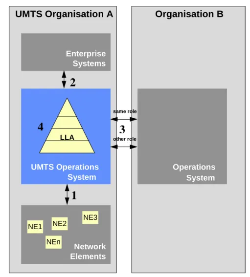
Figure 1 illustrates the UMTS Management Reference Model. It shows the UMTS Operation System interfacing with other systems.
The present document (and the rest of the 3GPP UMTS Management detailed specifications) addresses the UMTS Operations System (function and architecture wise) and the interfaces to the other systems (information and protocol wise).
The present document does not address the definition of any of the systems, which the UMTS Operations System may interface to. The rest of the 3GPP specifications regarding UMTS Management will not cover them either.
It is not the approach (nor it is possible) to re-define the complete management of all the technologies that might be used in the provision of UMTS. However, it is the intention to identify and define what will be needed from the perspective of UMTS management.
A number of management interfaces in a UMTS network are identified in figure 1, namely: 1) between the NEs and the Operations System of a single UMTS Organisation:
a) network element to element management level; b) element management to network management level.
2) between the Operations System and the Enterprise Systems of a single UMTS Organisation; 3) between Operations Systems of different UMTS Organisations;
4) within the Operations System of a single UMTS Organisation.
The present document focuses on management interfaces of type 1 from the above list, while interfaces of types 2 & 3 will be identified in the present document. Detailed specification of these interfaces is For Further Study (FFS). Interfaces of type 4 are beyond the scope of standardisation.
NOTE: Both TeleManagement Forum and ITU-T are carrying out work with interfaces of type 3. within the Operations System of a
UMTS Organisation A
•
Organisation B
UMTS Operations
System
LLAEnterprise
Systems
Operations
System
Network
Elements
NE1 NE2
NE3
NEn
same role
other role
1
2
4
3
5.2
Interfaces to Enterprise Systems (Type 2)
It is the approach to define a UMTS Management that fully fits into the enterprise processes needs of the UMTS Organisations. One of the essential issues of today's way of running telecommunications businesses is integral operation (e.g.: customer care, from service subscription to billing, from order fulfilment to complaint management).
Enterprise Systems are those Information Systems that are used in the telecommunication organisation but are not directly or essentially related to the telecommunications aspects (Call Centres, Fraud Detection and Prevention Systems, Invoicing etc.).
Standardising Enterprise Systems is out of the scope of 3GPP work, since it involves many operator choices
(organisational, etc.) and even regulatory. Also Enterprise Systems are often viewed as a competitive tool. However, it is essential that the requirements of such systems are taken into account and interfaces to the UMTS Operations Systems are defined, to allow for easy interconnection and functional support.
5.3
Interfaces to NEs (Type 1)
In some cases, the management interfaces to NEs have been defined bottom-up, trying to standardise the complete O&M functionality of the various NEs.
For UMTS management, a top-down approach will be followed to streamline the requirements from the perspective of UMTS Operators top priority management processes.
It is assumed that this will not fully cover the O&M functionality of all NE types in UMTS at once, therefore a part of the functionality will be phased for further work and consideration. Some proprietary solutions (local and/or remote) will be needed in the interim. The rational of this approach is not only the best use of resources, but also to follow a pragmatic step-wise approach that takes into account the market forces (the manufacturers and operators capabilities). A further rational is to define clear and easy to agree steps that allow Management functionality to be implemented in the same time frame as the telecom functionality in the network (i.e. to synchronise the management and network releases). The approach for NE Management Interfaces will be to concentrate on protocol independent information models, allowing a mapping to several protocol suites. The rational is:
- due to the convergence of Information and Telecommunication technologies in UMTS, it is required to work on a more open approach (acknowledging the market status and foreseen evolutions);
- the life cycle of information flows is 10 to 20 years, while that of protocols is 5 to 10 years;
- developments in automatic conversion from information models to various protocols/technologies will allow a more pragmatic and open approach (e.g. UML to GDMO, UML to IDL).
However, it is the intention to a least recommend one mapping for each interface.
5.4
Interfaces to other Operations Systems (Type 3)
UMTS Management considers integrally the interaction between the Operations Systems of other legal entities for the purpose of providing UMTS services.
There are two major types of interfaces to other management systems:
1) to other UMTS Operations Systems (i.e. other from other UMTS operators); 2) to other Operations Systems (i.e. to non-UMTS operators).
The first type deals with co-operation to provide UMTS services across a number of UMTS networks (e.g. roaming related interactions). The second type deals with client-server relationship to other operators (e.g. to leased lines providers, to added value service providers, etc.).
The approach that will be followed is to identify and define integral processes, not taking into account in the first step, how many operators or operations systems might be involved, but rather concentrating on the interactions between them (i.e. assuming a UMTS operator encompasses all functionalities). A further step will be to consider and define extra requirements (security, confidentiality etc.) when part of the process involves interactions with other operators Operations Systems (OSs).
5.5 Interface
definition
The Management interfaces are studied here from four different perspectives or levels:
1) logical (information model and flows used in the relationship manager-agent, or equivalent);
2) application protocol (end-to-end, upper layers protocol running between manager-agent, or equivalent); 3) networking protocol (lower layer protocols carrying the information in/out the manager and agent, or
equivalents);
4) physical (mapping of the manager and agent, or equivalents, roles into physical entities).
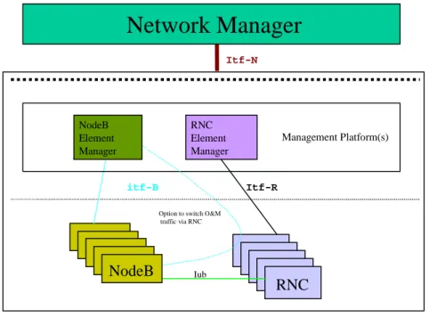
Figure 2 shows the management interfaces of one part of the UMTS (the Radio Network), by way of illustration of interfaces of types 1a and 1b).
NodeB
RNC
NodeB
NodeB
NodeB
RNC
RNC
RNC
RNC
RNCElement Manager
Management Platform(s)
Iub
itf-B Itf-R
Itf-N
Option to switch O&M traffic via RNC
Network Manager
NodeB Element Manager
NodeB
Figure 2: Radio Network Management Interfaces
Figure 2 identifies the following Management Interfaces:
- Itf-B - between Node B & its Manager (physically, this may be a direct connection or via the RNC) (type 1a). - Itf-R - between RNC & its Manager (type 1a).
- Itf-N – between Network & Network Manager (type 1b).
5.6 Logical
level
For type 1b interfaces (such as Itf-N in Figure 2 above) interactions at this level are fully standardised by 3GPP in terms of protocol independent Network Resource Models (static information definition) and IRP Information Services (information flows) where available. These protocol-independent Network Resource Models and IRP Information Services are hereafter referred to as IRP Information Models (Integration Reference Point Information Models).
5.7
Solution Set (SS) level
For each IRP Information Model at the logical level there will be at least one IRP Solution Set defined. An IRP Solution Set is a mapping of the IRP Information Service to one of several technologies (for a full definition refer to subclause 3.1).
See Annex C for the valid UMTS Management IRP Solution Sets.
5.8
Application Protocol level
This level covers the set of primitives used to pass information across a given interface and the means to establish associations between the application entities (including the related addressing aspects) across a given interface. Generally, the Application Protocol Suite used for the interaction between entities across a given interface is optional within the valid UMTS Management Application Protocol Suites (see Annex A for a list of UMTS Management Protocol Suites). However, in the case of interfaces of type 1b (such as Itf-N in figure 2 above) at least one of those protocol suites will be chosen as the standard protocol suite.
It is the intention to consider following attributes of each application protocol in making this decision:
CMIP:
- Very flexible;
- Powerful information modelling capability, therefore, in turn, complex to implement;
- Complex to integrate managers (specifically if CMIP stacks from different vendors are used in the agents and manager(s));
- Process hungry;
- Heavyweight stack (e.g. prevents it from being implemented on NodeB); - Potential reuse of GSM and ITU-T standards and implementation; - High on Cost Of Goods.
SNMP:
- is well used in other Telecom areas (e.g. ATM management);
- has inadequacies for Configuration Management (relatively simple/poor information modelling capability for management MIBs make implementation of complex information models difficult, although not impossible); - supports auto-discovery of elements on the management network via MIB-II;
- has lower Cost Of Goods;
- more choice of "off the shelf commercial systems and software" (see subclause 7.2 and 3GPP TS 32.102 [101]).
CORBA-IIOP:
- very powerful and flexible; - low Cost Of Goods;
5.9
Networking Protocol level
Whatever standardised protocol suite at the networking level that is capable of meeting the functional and operational requirements (including the network addressing aspects) of the Logical and Application Protocol levels of a given UMTS management interface, is a valid Networking Protocol for that interface.
A number of requirements shall be met by the Networking Protocol, as follows: - capability to run over any bearer (leased lines, X.25, ATM, Frame Relay ...);
- support of existing transport protocols and their applications, such as OSI, TCP/IP family, etc.; - widely available, cheap and reliable.
The Internet Protocol (IP) is a Networking Protocol that ideally supports these requirements. IP also adds flexibility to how management connectivity is achieved when networks are rolled out, by offering various implementation choices. For instance, these may take the form of:
- Dedicated management intranets.
- Separation from or integration into an operator's enterprise network.
- Utilisation, in one-way or another, of capacities of the public Internet and its applications or other resources.
5.10 Physical
level
Though the interaction at the logical level takes place between the UMTS Management System and the UMTS NEs, it is left to the implementer’s choice the possibility to use the Q-Adapter (see Note) concept of ITU-T TMN Architecture as physical implementation (as defined in ITU-T Recommendation M.3010 [1]).
NOTE: Q-Adapter needs to be interpreted here in a wider sense than in ITU-T Recommendation M.3010 [1], since UMTS will consider other application protocols different to CMIP.
The present document does not preclude the usage of Q-Adapters at other interfaces of the UMTS Management.
5.11 Compliance
conditions
For a UMTS entity (Management System or NE) to be compliant to a given UMTS Management Interface, all the following conditions shall be satisfied:
- it implements the management functionality following the Information Model and flows specified by the relevant 3GPP UMTS Management Interface Specifications applicable to that interface;
- it provides at least one of the IRP Solution Sets (where available) related to the valid Application Protocols specified by 3GPP UMTS Application Protocols for that interface (see Annex A). For each interface at least one of the valid protocols will be recommended;
- it provides at least one standard networking protocol;
- in case the entity does not offer the management interface on its own, a Q-Adapter shall be provided. This Q adapter shall be provided independently of any other UMTS NE and/or UMTS Management System.
6
UMTS Management Processes
The present document details the general aspects of an UMTS Management system. It describes primarily the management processes that collectively support Customer Care Service Development & Operations, and Network & Systems Management Processes in an UMTS network.
These management processes are based on the widely accepted Telecom Operations Map from the TeleManagement Forum [100]. They map onto the Service and Network Management layers as defined in the ITU-T Recommendation M.3010 appendix II [1] as depicted in Figure 3 below.
Customer
Order
Sales Problem
Handling
Customer QoS Management
Invoicing/
Service
Configuration Discounting
Service Development Planning/
Service Quality Management
Rating and Customer Interface Management Process
Customer Care Processes
Service Development and Operations Processes
Network and Systems Management Processes
Information Systems Management Processes Collections
Service Problem Resolution Handling
Network Provisioning Network
Planning/ Development
Network Data Management Network
Maintenance & Restoration Network
Inventory Management
Physical Network and Information Technology Element Management, Technology Related
Service Management Network Management
Figure 3: Telecom Operations Map Business Process Model (* imported from [100])
(Service & Network Management shading added in the present document)
The present document details the UMTS Management Functional Architecture. This is done by applying each of the management functions to the UMTS management processes.
The management functions are: - fault management;
- configuration management (including equipment inventory);
- performance management (including quality of service management); - roaming management;
- accounting;
- customer profile management; - service deployment; - fraud management; - security management; - software management.
All UMTS management processes have functions in several management areas. By identifying only those processes and interfaces relating to a certain management function, for example performance management, it is possible to take a slice through the Telecom Operations Map that details the functional architecture for performance management, this will be the approach taken by the present document.
7 Process
decompositions
This clause gives a short description of each of the UMTS management processes introduced in “TMF Telecom Operations Map” [100]. To see a more detailed description and process spider diagram for each process, refer to “TMF Telecom Operations Map”[100].
7.1
Customer Interface Management
The Customer Interface Management Process directly interacts with customers and translates customer requests and inquiries into appropriate "events" such as, the creation of an order or trouble ticket or the adjustment of a bill.
7.2 Sales
The Sales Process encompasses learning about the needs of each customer, and educating the customer about the communications services that are available to meet those needs.
7.3 Ordering
The Ordering Process includes all the functions of accepting a customer's order for service, tracking the progress of the order, and notifying the customer when the order is complete.
7.4 Problem
Handling
The Problem Handling Process is responsible to receive service complaints from customers, resolve them to the customer's satisfaction and provide meaningful status on repair or restoration activity.
7.5
Customer QoS Management
This process is concerned with UMTS Quality of Service (QoS) and its measurement, management and reporting.
7.6
Invoicing and Collection
This process encompasses sending invoices to customers, processing their payments and performing payment collections.
7.7
Service Planning and Development
This process encompasses:- designing technical capability to meet specified market need at desired cost;
- ensuring that the service (product) can be properly installed, monitored, controlled, and billed;
- initiating appropriate process and methods modifications, as well as initiating changes to levels of operations personnel and training required;
- initiating any modifications to the underlying network or information systems to support the requirements; - performing pre-service testing that the technical capability works and that the operational support process and
systems function properly;
- ensuring that sufficient capacity is available to meet forecasted sales.
7.8 Service
Configuration
This process encompasses the installation and/or configuration of service for specific customers, including the installation/configuration of customer premises equipment.
7.9
Service Problem Resolution
This process encompasses isolating the root cause of service affecting and non-service affecting failures and acting to resolve them. Typically, failures reported to this process affect multiple customers.
7.10
Service Quality Management
This process supports monitoring service or product quality on a service class basis in order to determine: - whether service levels are being met consistently;
- whether there are any general problems with the service or product; - whether the sale and use of the service is tracking to forecasts.
7.11
Rating and Discounting
This process encompasses:
- applying the correct rating rules to usage data on a customer-by-customer basis, as required; - applying any discounts agreed to as part of the Ordering Process;
- applying promotional discounts and charges; - applying outage credits;
- applying rebates due because service level agreements were not met; - resolving unidentified usage.
7.12
Network Data Management
In general, this process is responsible for the collection of performance/usage data and events for the purpose of network performance, usage and traffic analysis. This data is also an input to the Rating and Discounting process at the Service Management Layer.
7.13
Network Maintenance and Restoration
This process encompasses maintaining the operational quality of the network, in accordance with required network performance goals.
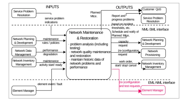
NOTE: 3GPP have added an additional process flow to this process. For this reason a modified spider diagram for this process is included in Figure 4 below (changes highlighted in red). This change has been submitted to TMF for inclusion in the Telecom Operations Map (TOM), when the changes is incorporated in the TOM the diagram can be removed from the present document.
Network Maintenance & Restoration service problem indications NML-SML interface Service Problem Resolution EML-NML interface work order, start/ stop/ cancel Network Data Management performance degradation Service Problem Resolution Report and progress problems based on incident, thresholds, etc. Schedule and notify of Planned Mtce.
Network Inventory Management
Element Manager
· problem analysis (including testing)
· network quality maintenance and restoration
· maintain historic data of network problems and performance
element event / fault Network Planning
& Development
maintenance rules / policies
Network Inventory Management
maintenance activity start/ ready
Network Provisioning (re-)configuration request Network Planning & Development capacity request OUTPUTS INPUTS
Customer QoS Planned
Mtce.
Element Manager (re-)configuration
and test requests
NOTE: Red colours in this figure indicate changes to Telecom Operations Map not yet approved by the TMF.
Figure 4: Network Maintenance and Restoration Process
7.14
Network Inventory Management
This process encompasses anything to do with physical equipment and the administration of this equipment.
7.15 Network
Provisioning
This process encompasses the configuration of the network, to ensure that network capacity is ready for provisioning of services.
7.16
Network Planning and Development
This process encompasses development and acceptance of strategy, description of standard network configurations for operational use, definition of rules for network planning, installation and maintenance.
8
UMTS Management Functional Architecture
8.1
TM Architectural aspects
The basic aspects of a TM architecture, which can be, considered when planning and designing a TM are: - the functional architecture;
- the information architecture; - the physical architecture.
The management requirements from the business needs are the base for the functional architecture, which describe the functions that have to be achieved. The information architecture defines what information that has to be provided so the functions defined in the functional architecture can be achieved. The physical architecture has to meet both the
functional architecture and the information architectures. These relationships are shown in Figure 5 below. The present document addresses the Functional Architecture, the Physical Architecture is addressed in 3GPP TS 32.102 [101].
Business needs
Functional Architecture
Information Architecture
Physical Architecture
Cost Performance
Legacy Preferences
Figure 5: Architectural relationship
8.2 Performance
Management
Figure 6 below makes a cut through the Telecom Operations Map from a Performance Management perspective. Although this "cut slice" is quite large it does not contain all and everything related to Performance Management. But it contains all processes and interfaces mainly involved in Performance Management. To make Figure 6 clearer different thickness of lines have been used to illustrate the different importance of the accordingly marked interfaces.
I: Customer
II: Customer Interface Management
Performance Complaints V: Problem Handling IV: Order Handling Performance Complaints Scheduled Reports
XII: Rating & Discounting
X: Service Problem Resolution VIII: Service Planning & Development XIII:Network Planning & Development XIV: Network Provisioning XVI: Network
Maintenance & Restoration
XVII: Network Data Managment
XVIII: Network Element Management
VI: Customer QoS Management IV: Order
Handling
Required Reports QoS & SLA Terms, Profiles SLA Violations Register SLA Terms Problem Reports Trouble Notification SLA Violations/ Outage Notifications Trouble Reports Status Reports Resolution Notification Trouble Notification
Usage & Performance Data XI: Service Quality Management Quality Objectives Performance Goals Capacity Requests Network Change Start/Modify Monitoring Performance Degradation Service Affecting Problem Planned Outages Usage Information Performance/Usage Trend Requests & Information Service Problem Data/Planned Maintenance Sevice Class Quality Data Network Performance Data QoS Violations
Problem Data / Planned Maintenance
Request
Figure 6: Information flow to support Performance Management
8.3 Roaming
Management
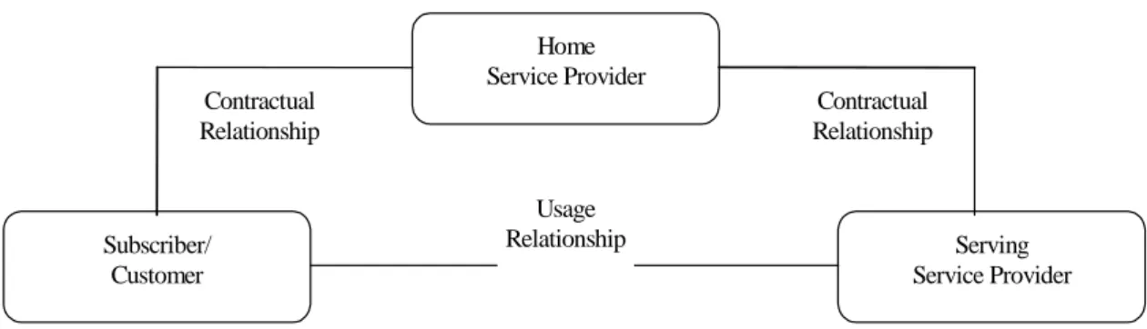
This example describes a unique, for mobile networks, management task. Roaming is a service provided by mobile service providers where customers of a home service provider may use the infrastructure of another, a serving service provider (see Figure 7). The idea is that a customer receives the same service when it roams in another network, as it would receive at home.
Subscriber/ Customer
Home Service Provider
Serving Service Provider Contractual
Relationship
Contractual Relationship Usage
Relationship
Figure 7: Relationships between Subscriber, Home and Serving Service Provider
In order to make this happen, the home service provider and serving service provider need a contractual relationship called a roaming agreement. The roaming agreement can be an ordinary direct agreement between both service providers or it can be established by the means of a clearinghouse.
In any case the roaming agreement regulates at least the following items: - tariffing and pricing;
- signalling and traffic interconnection;
- CDR exchange format and exchange schedule; - problem handling; and many others.
Today's mobile networks have roaming agreements with tens of other networks. With 3rd Generation mobile networks coming, this number is expected to increase to hundreds if not more. All these roaming agreements have an impact on many parts of the network.
The handling of this complex process requires an excellent understanding of roaming agreement management. To aid this understanding Figure 8 below is provided. All information flows, which are not effected or not changed by roaming agreement management, have been omitted to aim readability.
NOTE: The information flows shown in Figure 8 are intended to illustrate the flow of management information required to support roaming in 3rd Generation networks.
The information flow illustrated in Figure 8 is an overlay onto the main information flow of a serving mobile service provider to support it's own subscribers. This overlay information flow of the serving service provider is triggered by the request to establish or update a roaming agreement issued by the customer.
In this context the home service provider is classified as a customer of a serving service provider (customer in this context does not refer to an individual customer of the home service provider!).
The home service provider (customer) would like to offer roaming to the serving service provider to its subscribers. The roaming agreement management information flow consists of one major and two optional supporting information flows:
- customer care information flow (solid line)
This is the major information flow supporting all contract related activities: negotiating tariffs, negotiating SLAs, trouble handling, roaming accounting file exchange,...
- new service facilities information flow (dash-dotted line)
This is an optional supporting flow which takes place if the support of an roaming agreement requires the introduction of new services or a configuration change of existing services.
- new network facilities information flow (dashed line)
This is an optional supporting flow which takes place if the support of an roaming agreement requires the introduction of new network facilities or a configuration change of existing network facilities.
Service/Product Development and Maintenance Customer Care Customer Interface Management Customer V: Problem Handling
II: Customer Interface Management I: Customer
1: Roaming Agreements
2: Define, negotiate and update tariffs
and services
IV: Order Handling
13: Register SLA Terms
17: Trouble Notifications and Reports
IX: Service Configuration
III: Sales 3: Roamingorder
VIII: Service Plan. &
4: New Roaming requirements
VII: Invoicing Collection
14: Status & Completion
5:Service Prices
XII: Rating & Discounting
11: Assign Service Profile (VHE) 20: Roaming Accounting Files 19: Billing Records 18: Roaming SLA violations 12: Assign Roaming
Tariff plan 21: Invoices Payments Network and Systems Management XIII: Network Plan. &
7: New Roaming Relationship
XIV: Network Provisioning
8: configuration requirements
9: Assignment and Configuration ready 10: Completion 6: Service Options VI: Customer QoS 15: Scheduled Reports 16: Roaming SLA violations
Figure 8: Information flow to support Roaming Management
8.4 Fraud
Management
Fraud and all the activities to detect and prevent fraud are quite common for most of the networks. Nonetheless it should be mentioned that two mobile network specific services: mobility and roaming make fraud detection and fraud prevention even more complicated: The mobile service provider does not know where is the "end of the wire" leading to the home of a fraudulent customer. In case of roaming the situation is even worse. The fraudulent customer uses the network facilities of another – the serving - service provider, which means that it is to a large extent out of control of the home service provider.
Typically fraud management in mobile networks (i.e. fraud detection and prevention) covers at least the following functions:
- classification of customers according to levels of fraud risk (based on demographic and credit information); - revision of the fraud risk level (based on usage information, payment behaviour,... near real time or off-line); - detection of fraud patterns (in real time or near real time);
- taking the appropriate actions to suspend service provision, even if the customer is using a different network than its home (the customer is roaming);
- for visiting customers (i.e. those who are roaming) it may consult the home provider and/or international repositories (e.g. the Central Equipment Identity Register – CEIR for GSM mobile equipment).
Fraud management is present in several processes of the Telecom Operations Map. Figure 9 below shows the occurrence of fraud detection and fraud prevention functions listed above to the existing processes of the Telecom Operations Map.
Service/Product Development and Maintenance Customer Care Customer Interface Management Customer V: Problem Handling
II: Customer Interface Management
Ib: Home
13a: Trouble Notifications and Reports
IV: Order Handling
3: Register fraud risk
12: Trouble Notifications and Reports IX: Service Configuration 1: Credit check request VI: Customer QoS
XII: Rating & Discounting 5: Activate Service 9: Fraud detected 7: Credit line exceeded/ change (new) 4: Register credit line Network and Systems Management XVII: Network Data Mgmt. 8: Usage Patterns 11: Suspend/Resume/ Reconfigure Service Ia: End Credit Bureau
13b: Trouble Notifications and Reports 6: Usage Data Fraud Prevention Pool 2: Fraud information request Treasury 10: Payment behavior (new) 14: Register
Fraud info (new)
16: Roamer Usage Data (new) 15: Customer monitoring request (new) VIII: Service Plan. & Market Develop. 0: Minimize threats Figure 9: Information flow to support Fraud Management
Fraud management functions are present in many processes of the Telecom Operations Map. What makes fraud management so difficult is the fact that it consists of many process flows segments instead of one or two continuous process flows. This is also the reason making the presentation of fraud management in the Telecom Operations Map so difficult.
Although it seems that all required functions to support fraud management exist in the Telecom Operations Map, fraud management requires the introduction of some new interfaces (marked accordingly in Figure 9) to be efficient.
- Pre service: prevent fraud
- Potential threats and leaks should be analysed during Service Planning and Design and the service should be optimised to be as resistant to threats as possible.
- Fulfilment: prevent fraud
- Order Handling initiates the classification of customers according to levels of fraud risk. This includes a credit check request; and
- The determined initial fraud risk level will be registered at Problem Handling.
- A credit line depending on the customer's fraud risk level will be registered at Rating & Discounting. - Finally the ordered Service will be activated fully or partly depending on the fraud risk level. - Assurance 1: detect fraud
- Normal usage data (preferably hot billing usage data) is transferred to Rating and Discounting.
- Rating & Discounting checks billing records for exceeding established credit lines and reports this Problem Handling (new).
- Assurance 2: detect fraud
- Usage data/patterns are sent to the Customer QoS Management for analysis.
- If Customer QoS Management detects a fraud then it sends an according notification to Problem handling which can decide on appropriate actions to take in order to prevent or stop fraud.
- Assurance 3: detect fraud
- Treasury informs Problem handling about the payment behaviour of customers. - Assurance 4: stop fraud
- Problem Handling can decide on appropriate actions to take in order to prevent or stop fraud by reconfiguring the service; and/or
- Contacting via Customer Interface Management
- The Customer (either the end-customer or the home service provider in case of a visiting customer). - Assurance 5: prevent fraud
- Problem handling may register fraud information in the Fraud Prevention Pool. - Assurance 6: stop roaming fraud
- Problem handling requests the monitoring of a visiting customer on a trouble notification request of its home service provider according to the roaming agreement.
- Network Data Management delivers the usage data to the requesting home service provider.
8.5 Fault
Management
Fault Management is accomplished by means of several Processes/Sub-processes like fault detection, fault localisation, fault reporting, fault correction, fault repair, etc… These Processes/Sub-processes are located over different
management layers, however, most of them (like fault detection, fault correction, fault localisation and fault correction) are mainly located over the Network Element and Network Element Management layers, since this underlying network infrastructure has the 'self healing' capabilities.
It is possible, however, that some faults/problems affecting the telecom services are detected within the "Network and Systems Management" layer, by correlating the alarm/events (originated by different Network Elements) and correlating network data, through network data management.
Network data management logically collects and processes both performance and traffic data as well as usage data. While the Fault Management triggered within the Network Element and NE Management layers is primarily reactive, the Fault Management triggered within the Network and Systems Management layer is primarily proactive. Meaning triggered by automation rather than triggered by the customer; and this is important for improving service quality, customer perception of service and for lowering costs.
Focusing on the Network and Systems Management layer, when a fault/problem is detected, no matter where and how, several processes are implicated, as described in Figure 10 below.
8.5.1
Telecom Operations Map (TOM)
Figure 10 below taken from the Telecom Operations Map [100] shows an example of how Fault Management data can be used to drive an operator’s service assurance process. Service assurance then becomes primarily proactive, i.e. triggered by automation rather than triggered by the customer. It is argued that this approach is key to improving service quality, customer perception of service and for lowering costs.
Service Problem
Resolution Service QualityManagement
2. report degradation 8. report problem data 9. SLA impact to Fulfilment Processes Problem Handling
7. trouble report (Trouble Ticket) customer alert(TT) (SLA rebate, etc) to Billing Processes Monitor SLAs Report Network Data Management 1.network data Network Inventory Management Allocate Resources Determine SLA Violations Network Maintenance & Restoration Decide Repair Test Isolate Root Cause 5.notify problem/fix 10. service impact Detect Fault Detect Perf/Traffic Problems 1.alarm/event data 4.Work order 6. (Service (Re) Configuration) Decide Repair
Network Element Management & Network Elements
Other Providers
Customer QoS Management Key: Activities Processes Cross FAB Process I/f Inter-process I/f Inter SP process I/f3. re-configuration and test requests
Figure 10: Service Assurance Process Flow (* imported from [100])
TOM assurance activities (and their associated interfaces) shown in Figure 10 above can be associated with ITU-T TMN service components from 3GPP TS 32.111-x "3G Fault Management" [3] according to Table 1 below:
Table 1: ITU-T TMN Service Component
3GPP TS 32.111-x [3]
TOM Network Management Assurance Activities
Alarm Surveillance Detect Fault
Fault Localisation Isolate Root Cause
Fault Correction Decide Repair / Allocate Resources Testing Test
The TOM assurance example shown in Figure 9 also recognises that Performance Management data can also be used to detect network problems.
The TOM assurance example also adds some detail to the Service Management Layer by showing how activities such as determining and monitoring Service Level Agreements (SLAs) and trouble ticket reporting are interfaced to the Network Management layer.
8.5.2
General Requirements, Service Components and Functions
Fault Management service components and functions are an area well documented by existing ITU-T, ETSI and other standards. The GSM Specification GSM 12.11 (Fault Management of the Base Station System) provides a
comprehensive explanation and specification of the relevant ITU-T TMN standards. This has been used as a basis for the 3GPP TS 32.111-x "3G Fault Management" [3].
3GPP TS 32.111-x [3] is based on the following service components: - alarm surveillance;
- fault localisation; - fault correction; - testing.
Please refer to 3GPP TS 32.111-x [3] for complete details.
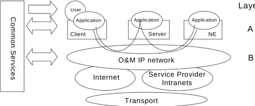
8.6 Security
Management
This clause describes an architecture for security management of the TMN that is divided into two layers, as shown in Figure 11. No individual layer is dependent on any specific technology in the other one.
User
Server
Layer
A
B
C
o
m
m
on Se
rv
ic
e
s Internet
O&M IP network
Application
NE Client
Application Application
Service Provider Intranets
Transport
Figure 11: Security Management Architecture
8.6.1
Layer B - O&M IP Network
Some Service Providers might build their O&M IP network as a completely private, trusted network. In the normal case though, the O&M IP network should be regarded as partly insecure due to its size, complexity, limited physical security and possible remote access from dial-up connections or from the Internet. The only security service provided then is that the O&M IP network is logically separated from the Internet. IP infrastructure aspects on security are handled to the extent possible utilizing IP classic features (addressing schemes, DNS, DHCP, BOOTP, protection with firewalls etc.). Additionally, a trusted IP-environment to the application level might be provided, e.g. an environment with no
masquerading IP-hosts and where potential intruders cannot communicate. One way to accomplish such a secure DCN is to use IP security mechanisms (IPSec; see IETF RFC2401 [7]) to achieve authentication of IP hosts (servers, gateways, Network Elements) and optional encryption of O&M traffic. Note however that the secure DCN does not authenticate users.
8.6.2
Layer A - Application Layer
On this layer we find Telecom Management applications performing their tasks in the normal management functional areas. Managed objects residing in the network resources are often accessed or manipulated.
Layer A provides authentication of users ensuring that every party involved in O&M traffic is securely authenticated against every other party. The implementation of the authentication service supports "single log-on" (a user only has to
![Figure 3: Telecom Operations Map Business Process Model (* imported from [100]) (Service & Network Management shading added in the present document)](https://thumb-us.123doks.com/thumbv2/123dok_us/8521762.2288092/19.892.138.742.111.694/telecom-operations-business-process-imported-service-network-management.webp)


![Figure 10 below taken from the Telecom Operations Map [100] shows an example of how Fault Management data can be used to drive an operator’s service assurance process](https://thumb-us.123doks.com/thumbv2/123dok_us/8521762.2288092/29.892.99.790.242.665/figure-telecom-operations-example-management-operator-service-assurance.webp)