For heating contractors during project planning
Logamatic LON-Gateway
Contents
1 Explanation of symbols and safety instructions . . . 4
1.1 Guideline to symbols . . . 4
1.2 Safety instructions . . . 5
2 Product description . . . 6
2.1 Correct use . . . 6
2.2 Disposal . . . 6
2.3 Product description . . . 7
2.4 Specifications . . . 8
2.5 Specified communication objects . . . 8
2.6 Logamatic LON-Gateway firmware . . . 10
2.6.1 Firmware when delivered . . . 10
2.6.2 Procedure for updating firmware . . . 10
3 Network interface . . . 11
3.1 Overview of the SNVTs for variant 2 boilers . . . 11
3.2 Description of the SNVTs for variant 2 boilers . . . 14
3.2.1 General . . . 14
3.2.2 Heating zones . . . 16
3.2.3 DHW heating . . . 18
3.2.4 Strategy . . . 20
3.2.5 Floor-standing boilers . . . 21
3.2.6 Solar . . . 22
3.3 Overview of the SNVTs for variant 4 boilers . . . 23
3.4 Description of the SNVTs for variant 4 boilers . . . 26
3.4.1 General . . . 26
3.4.2 Heating zones . . . 28
3.4.3 DHW heating . . . 30
3.4.4 Strategy . . . 32
3.4.5 Boiler 1 . . . 33
3.4.6 Boiler 2 . . . 35
4 Operating basics . . . 38
5 Incorporation of Logamatic 4000 in LON networks via Logamatic LON-Gateway . . . 39
5.1 Structure of the hardware . . . 39
5.2 Creating LON networks . . . 39
5.2.1 Commissioning LON networks . . . 40
5.2.2 Decommissioning LON networks . . . 40
6 The LON-Gateway as LonMark object . . . 41
6.1 Variant 2 boiler . . . 41
6.2 Variant 4 boiler . . . 42
1
Explanation of symbols and safety instructions
1.1
Guideline to symbols
Warnings
Signal words at the beginning of a warning are used to indicate the type and seriousness of the ensuing risk if measures for minimizing damage are not taken.
• NOTE indicates that minor damage to property may occur. • CAUTION indicates possible minor to medium personal injury. • WARNING indicates possible severe personal injury.
• DANGER indicates that severe personal injury may occur. Important information
Additional symbols
Warnings are indicated in the text by a warning triangle and a gray background.
In case of danger from electric shock, the exclamation point on the warning triangle is replaced with a lightning symbol.
Important information that presents no risk to people or property is indicated with this symbol. It is separated by horizontal lines above and below the text.
Symbol Meaning
B Sequence of steps
Æ Cross-reference to other points in this document or to other documents
• Listing/list entry
– Listing/list entry (2nd level)
1.2
Safety instructions
Installation and commissioning
The Logamatic LON-Gateway interface module has been designed and built in accordance with currently recognized standards and safety requirements.
However, dangers or property damage may arise if it is used improperly. B Observe these instructions to ensure satisfactory operation.
B The appliance may only be installed and started up by a trained installer.
B All changes and adjustments made via superior control systems must meet the heating system requirements.
Risk of death from electric shock
B The power supply must be connected by a qualified electrician. B The terminal diagram must be followed.
B Before opening the appliance, isolate all poles of the mains power supply and secure against unintentional reconnection.
B Never install this appliance in wet rooms.
B Ensure that a circuit breaker is available to disconnect all poles from the mains power supply. If there is no circuit breaker, you will need to install one.
Risk of damage from operator error
Operator errors can cause injury and damage to property.
B Ensure that children never operate this appliance unsupervised or play with it.
B Ensure that only individuals who can operate this appliance correctly have access to it. WARNING: Only transformers with following specification are permitted:
6 V AC; 400 mA. The transformer is not part of the product! Please take care to use a reliable product which meets our requirements shown above. Do not mount the transformer internally!
Buderus does not accept responsibility for systems which contravene the Installation instruction or addition documentation in scope of delivery.
2
Product description
2.1
Correct use
The Logamatic LON-Gateway may only be used to connect Buderus boilers with control panel from the Buderus Logamatic 4000 control series to superior control and/or building control systems via LON-BUS.
2.2
Disposal
B Electronic components do not belong in household waste.
2.3
Product description
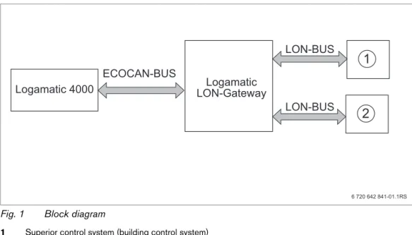
The Logamatic LON-Gateway is incorporated into a LON network via a twisted pair cable (twisted 2-wire line). The twisted pair cable is protected against reverse polarity.
Defined data of the Buderus control panel is implemented with the Logamatic LON-Gateway interface on standard network variable types (SNVTs) for the LON data bus. The communication includes forwarding of error messages, operating messages, and actual values, as well as changing of set points and operating modes for boilers and consumers.
Fig. 1 Block diagram
1 Superior control system (building control system)
2 LON Gateway
Making the electrical connections
Logamatic LON-Gateway
Connection of the Logamatic LON-Gateway with Logamatic 4000
ECOCAN-BUS interface (BUS communication), 3000 ft (1000 m) shielded cable
Connection of Logamatic LON-Gateway to LON networks
FTT-10A transceiver for incorporation via 2-wire cable (twisted pair) to standardized LON BUS network; line or free
Product features of the LON-Gateway
• Can be used with all digital Logamatic 4000 control panels
• Interface can be equipped after the fact for the superior control system or for LON thermostats, integration into existing building control technology/direct digital control (GLT/DDC)
• Interoperability through use of the standard network variable types (SNVT) assured according to LonMark®
• Provision of the SNVT data for systems consisting of:
2.4
Specifications
2.5
Specified communication objects
With the LON-Gateway, selected data from up to four Logamatic 4000 control panels can be exchanged via LON data bus with third-party control systems.
In addition to the communication objects for the first boilers, which are a component of the control panel, additional functions in the form of modules for multi-boiler systems, heating zones, DHW, and solar can be added.
Communication objects Variant 2 boiler Variant 4 boiler
Boiler 2 4
Heating zones 5 1
DHW zone with tank charging pump and recirculation pump
1 1
Solar thermal system for DHW heating 1
-Tab. 3 Variants
Unit Logamatic LON-Gateway
Power supply L 6 V AC, 400 mA
Frequency Hz 50/60 Hz
Power consumption VA 1.5
Dimensions (width/height/depth) inches (mm) 5-1/8" / 5-1/2" / 9/16"
(130/140/40)
Weight oz (g) 14 (400)
Operating temperature °F (°C) 40 to 122 (5 to 50)
Protection level IP40
Tab. 4 Specifications
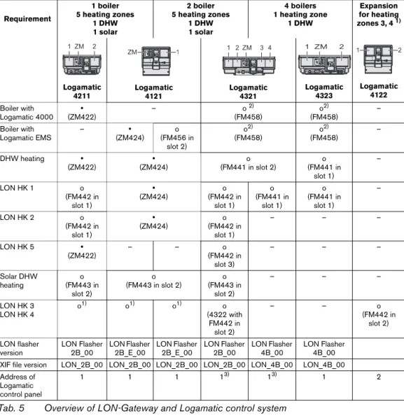
If heating zones are served via LON, no other remote controls, e.g. Buderus remote control BFU, may be connected to this heating zone.
Requirement
1 boiler 5 heating zones
1 DHW 1 solar
2 boiler 5 heating zones
1 DHW 1 solar
4 boilers 1 heating zone
1 DHW
Expansion for heating
zones 3, 4 1)
1) Logamatic 4122 required if LON heating zones 3 and 4 are required in one and two-boiler systems.
Logamatic 4211 Logamatic 4121 Logamatic 4321 Logamatic 4323 Logamatic 4122 Boiler with Logamatic 4000 y (ZM422)
– o 2)
(FM458)
2) Function module FM458 combines boiler with the Logamatic 4000 and Logamatic EMS control system.
o2) (FM458) – Boiler with Logamatic EMS – y (ZM424) o (FM456 in slot 2) o2) (FM458) o2) (FM458) –
DHW heating y
(ZM422)
y (ZM424)
o (FM441 in slot 2)
o (FM441 in
slot 1)
–
LON HK 1 o
(FM442 in slot 1) y (ZM424) o (FM442 in slot 1) o (FM441 in slot 1) o (FM441 in slot 1) –
LON HK 2 o
(FM442 in slot 1) y (ZM424) o (FM442 in slot 1) – – –
LON HK 5 y
(ZM422)
– – o
(FM442 in slot 3) – – – Solar DHW heating o (FM443 in slot 2) o (FM443 in slot 2)
o (FM443 in
slot 2)
– – –
LON HK 3 LON HK 4
o1) o1) o1) o
(4322 with FM442 in
slot 2)
– – o
(FM442 in slot 2) LON flasher version LON Flasher 2B_00 LON Flasher 2B_E_00 LON Flasher 2B_E_00 LON Flasher 2B_00 LON Flasher 4B_00 LON Flasher 4B_00
XIF file version LON_2B_00 LON_2B_00 LON_2B_00 LON_2B_00 LON_4B_00 LON_4B_00
Address of Logamatic control panel
1 1 1 13) 13) 1 2
2.6
Logamatic LON-Gateway firmware
2.6.1 Firmware when delivered
When delivered, the firmware version LON_Flasher_2B_00 is preinstalled. This version is for a heating system with floor-standing boilers with Logamatic 4321. If you need another firmware variant (e.g. LON_Flasher_4B_00) for your installation, it is easy to update the firmware. (see procedure for updating firmware)
2.6.2 Procedure for updating firmware
First the LON-Gateway must be connected to the power supply and connected on-site to your computer via the RS232 interface or USB converter.
B Obtain the desired firmware from Buderus and, start the LONFlasher*******.exe.
B Select the COM port.
B Start the update with the Flash button.
A display informs you about the current progress. The update is only complete when a message "...successful!" appears.
B When a message "...successful!" appears, confirm with OK. The update is complete.
After the successful update, disconnect the LON-Gateway from the line voltage for approx. 2 minutes to perform a reset. This completes the firmware update.
The firmware version of your LON-Gateway is displayed via the Logamatic ECO-SOFT 4000/EMS service software (Start communication -> Select COM port settings -> Direct connection).
You can find the correct COM port under: Windows XP from the device manager (Control panel -> System -> Hardware -> Device manager -> COM port).
Procedure for Windows Visa and Windows 7: Control panel > Hardware and Sound -> Device manager --> COM port.
3
Network interface
3.1
Overview of the SNVTs for variant 2 boilers
The prerequisite for the proper function is that the firmware on the LON-Gateway interface has at least the version number indicated below and the following application file is used:
Communication via the Logamatic LON-Gateway takes place using standard network variable types (SNVT). Standard configuration parameter types (SCPTs) are not used.
Alternative
Buderus
(alternative of the LON-Flasher)
LON application file (XIF file)
2 boilers with Logamatic EMS LON_Flasher_2B_E_00 LON_2B_00 2 boilers with Logamatic 4000 LON_Flasher_2B_00 LON_2B_00
Tab. 6
Set the system up for repeated reading of SNVTs, which ensure data exchange between the network participants.
No. Meaning SNVT type SNVT name
General
0 Time SNVT_time_ stamp(84) nviUhrzeit
1 Outdoor temperature SNVT_temp_p(105) nvoAussen_Tp
2 Error message 1 control unit addresses 1 + 2 SNVT_state(83) nvoFehler1 3 Error message 2 control unit addresses 1 + 2 SNVT_state(83) nvoFehler2 4 Error message 3 control unit addresses 1 + 2 SNVT_state(83) nvoFehler3 5 Error message 4 control unit addresses 1 + 2 SNVT_state(83) nvoFehler4
Heating zone 1
6 Change operating mode (D/N/A) SNVT_hvac_mode(108) nviHK1TgNtAt 7 Change room set point night temperature SNVT_temp_p(105) nviHK1RaumSNt_Tp 8 Change room set point day temperature SNVT_temp_p(105) nviHK1RaumSTg_Tp 9 Display room set point temperature SNVT_temp_p(105) nvoHK1Raum_S_Tp
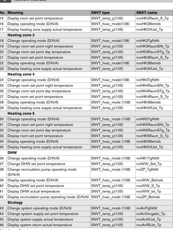
15 Display room set point temperature SNVT_temp_p(105) nvoHK2Raum_S_Tp 16 Display operating mode (D/N/A) SNVT_hvac_mode(108) nvoHK2Betrieb 17 Display heating zone supply actual temperature SNVT_temp_p(105) nvoHK2VLIst_Tp
Heating zone 3
18 Change operating mode (D/N/A) SNVT_hvac_mode(108) nviHK3TgNtAt 19 Change room set point night temperature SNVT_temp_p(105) nviHK3RaumSNt_Tp 20 Change room set point day temperature SNVT_temp_p(105) nviHK3RaumSTg_Tp 21 Display room set point temperature SNVT_temp_p(105) nvoHK3Raum_S_Tp 22 Display operating mode (D/N/A) SNVT_hvac_mode(108) nvoHK3Betrieb 23 Display heating zone supply actual temperature SNVT_temp_p(105) nvoHK3VLIst_Tp
Heating zone 4
24 Change operating mode (D/N/A) SNVT_hvac_mode(108) nviHK4TgNtAt 25 Change room set point night temperature SNVT_temp_p(105) nviHK4RaumSNt_Tp 26 Change room set point day temperature SNVT_temp_p(105) nviHK4RaumSTg_Tp 27 Display room set point temperature SNVT_temp_p(105) nvoHK4Raum_S_Tp 28 Display operating mode (D/N/A) SNVT_hvac_mode (108) nvoHK4Betrieb 29 Display heating zone supply actual temperature SNVT_temp_p(105) nvoHK4VLIst_Tp
Heating zone 5
30 Change operating mode (D/N/A) SNVT_hvac_mode (108) nviHK5TgNtAt 31 Change room set point night temperature SNVT_temp_p(105) nviHK5RaumSNt_Tp 32 Change room set point day temperature SNVT_temp_p(105) nviHK5RaumSTg_Tp 33 Display room set point temperature SNVT_temp_p(105) nvoHK5Raum_S_Tp 34 Display operating mode (D/N/A) SNVT_hvac_mode (108) nvoHK5Betrieb 35 Display heating zone supply actual temperature SNVT_temp_p(105) nvoHK5VLIst_Tp
DHW
36 Change operating mode (D/N/A) SNVT_hvac_mode (108) nviHK1TgNtAt 37 Change DHW set point temperature SNVT_temp_p(105) nviWW_Set_Tp 38 Change recirculation pump operating mode
(D/N/A)
SNVT_hvac_mode (108) nviZP_TgNtAt 39 Display operating mode (D/N/A) SNVT_hvac_mode (108) nvoWW_Betrieb 40 Display DHW set point temperature SNVT_temp_p(105) nvoWW_S_Tp 41 Display DHW actual temperature SNVT_temp_p(105) nvoWW_Ist_Tp 42 Display recirculation pump operating mode (D/N/A) SNVT_hvac_mode (108) nvoZP_Betrieb
Strategy
43 Change system operating mode (D/N/A) SNVT_hvac_mode (108) nviAnlTgNtAt 44 Change system supply set point temperature SNVT_temp_p(105) nviAnlVorgabe_Tp 45 Display system supply actual temperature SNVT_temp_p(105) nvoAnlVLIst_Tp 46 Display system return actual temperature SNVT_temp_p(105) nvoAnlRLIst_Tp
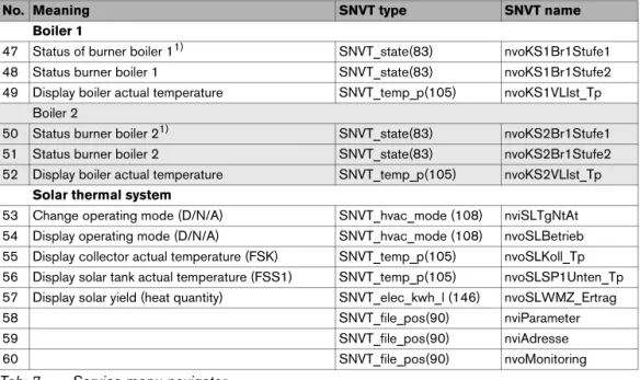
No. Meaning SNVT type SNVT name
Boiler 1
47 Status of burner boiler 11) SNVT_state(83) nvoKS1Br1Stufe1 48 Status burner boiler 1 SNVT_state(83) nvoKS1Br1Stufe2 49 Display boiler actual temperature SNVT_temp_p(105) nvoKS1VLIst_Tp
Boiler 2
50 Status burner boiler 21) SNVT_state(83) nvoKS2Br1Stufe1 51 Status burner boiler 2 SNVT_state(83) nvoKS2Br1Stufe2 52 Display boiler actual temperature SNVT_temp_p(105) nvoKS2VLIst_Tp
Solar thermal system
53 Change operating mode (D/N/A) SNVT_hvac_mode (108) nviSLTgNtAt 54 Display operating mode (D/N/A) SNVT_hvac_mode (108) nvoSLBetrieb 55 Display collector actual temperature (FSK) SNVT_temp_p(105) nvoSLKoll_Tp 56 Display solar tank actual temperature (FSS1) SNVT_temp_p(105) nvoSLSP1Unten_Tp 57 Display solar yield (heat quantity) SNVT_elec_kwh_l (146) nvoSLWMZ_Ertrag
58 SNVT_file_pos(90) nviParameter
59 SNVT_file_pos(90) nviAdresse
60 SNVT_file_pos(90) nvoMonitoring
1) Display of the output for boilers with Logamatic EMS
No. Meaning SNVT type SNVT name
3.2
Description of the SNVTs for variant 2 boilers
Note:
The right column indicates the number of bytes. 3.2.1 General
Format: YYYY/MM/DD hh:mm:ss
Note:
230 °F (110 °C) is an invalid value (e.g. no temperature sensor connected, sensor defective, etc.)
For the error list, see Chapter 7, page 43.
Error messages are displayed as 2-byte values (2 x 8 bits). The first byte (the first 8 bits seen from the left) is the interpretation of the error message of control panel address 2. The second byte (the remaining 8 bits) is the interpretation of the error message of control panel address 1:
Errors are displayed as binary values and must be converted to decimal values. By comparing with the error list (see Chapter 7, page 43), the associated texts are assigned to the error numbers. Example: see page 27
0 Time SNVT_time_ stamp(84) nviUhrzeit 7
Tab. 8 Value for comparison of the time in the Buderus control system with the LON network
1 Outdoor temperature SNVT_temp_p(105) nvoAussen_Tp 2
Tab. 9 Display of the current outdoor temperature
2 Error message 1 control panel address 1 + 2
SNVT_state(83) nvoFehler1 2
Tab. 10 Output for error messages: error 1 of control panel 1 and 2
First byte - error boiler 2 Second byte - error boiler 1
Display 0 0 0 0 0 0 0 0 0 0 0 0 0 0 0 0
Interpretation 20 21 22 23 24 25 26 27 20 21 22 23 24 25 26 27
Example:
Second, third, and fourth current errors in the control panel in question. List of the error list, see Chapter 7, page 43.
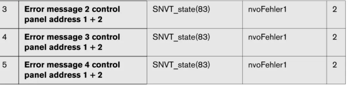
Interpretation as described for error message 1. 3 Error message 2 control
panel address 1 + 2
SNVT_state(83) nvoFehler1 2
4 Error message 3 control panel address 1 + 2
SNVT_state(83) nvoFehler1 2
5 Error message 4 control panel address 1 + 2
SNVT_state(83) nvoFehler1 2
3.2.2 Heating zones
This section describes only heating zone 1. For heating zones 2 to 5, the details apply accordingly.
Format:
Changing the operating mode
With the HVAC_heat / HVAC_off setting, the operating mode for the consumer is changed externally via the LON data bus.
Type of setback:
The type of setback set in the control panel has a direct influence on the behavior of the consumer in setback mode or night mode. The following functions are available for selection:
• Switch off: the heating mode with activation of the pump is turned off entirely with this operating mode, however the frost protection is active.
• Reduced: the controls are set to a lower room temperature set point (night temperature) and they constantly activate the heating pump. The controls work with a parallel heating curve moved downwards depending on the outdoor temperature.
• Outside stop: this operating mode combines the setback mode and the reduced heating mode. Below a set outdoor temperature, the boiler operates in reduced mode and above that temperature, in off mode.
Setting: 36 °F to 84 °F (2 °C to 29 °C) in 1-degree intervals
6 Operating mode (Day/Night/Auto) SNVT_hvac_mode (108) nviHK1TgNtAt 1
Tab. 13 Value for changing the operating mode of a heating zone
Value Designation Description
0 HVAC_AUTO The heating zone is controlled according to the set heating program (automatic mode).
1 HVAC_heat The heating zone is controlled in day mode (manual day mode). 6 HVAC_off The heating zone is controlled in setback mode (manual night mode –
see note about setback).
Tab. 14
7 Room set point night temperature
SNVT_temp_p(105) nviHK1RaumSNt_Tp 2
Notes:
• The room set point night temperature specifies the temperature level in the setback mode or night mode for the consumer. With this setting, the heating curve moves in parallel. If you change the room set point temperature by 2 °F (1 °C), then the supply temperature changes by approx. 6 °F (3 °C).
• The room set point night temperature is not active with the setback type "off."
• The room set point night temperature is not taken into account with the setting heating system "constant." The temperature set in the control panel for the heating zone and the temperature setback are active.
Setting: 52 °F to 86 °F (11 °C to 30 °C) in 1-degree intervals Notes:
• The room set point day temperature specifies the temperature level in day mode for the consumer. With this setting, the heating curve moves in parallel. If you change the room set point temperature by 2 °F (1 °C), then the supply temperature changes by approx. 6 °F (3 °C). • The room set point day temperature is not active with the setback type "off."
• The room set point night temperature is not taken into account with the setting heating system "constant." The temperature set in the control panel for the heating zone and the temperature setback are active.
8 Room set point day temperature
SNVT_temp_p(105) nviHK1RaumSTg_Tp 2
Tab. 16 Value for changing the set point temperature for the setback heating mode (day mode)
9 Room set point temperature SNVT_temp_p(105) nviHK1Raum_S_Tp 2
Tab. 17 Display of the currently-valid room set point temperature for the consumer
10 Operating mode (Day/Night/ Auto)
SNVT_hvac_mode (108)
nvoHK1Betrieb 1
Tab. 18 Display of the currently-valid operating mode for the consumer
11 Heating zone supply actual temperature
3.2.3 DHW heating
Format:
Changing the operating modeWith the HVAC_heat / HVAC_off setting, the operating mode for the consumer is changed externally via the LON data bus.
Set range: 86 °F to 140 °F (30 °C to 60 °C) (with approval up to 176 °F (80 °C)); in 1-degree intervals
Notes:
• The set point temperature for DHW heating specifies the temperature level for the consumer in automatic mode or day mode.
• If for DHW heating temperatures > 140 °F (60 °C) are desired, the range up to 176 °F (80 °C) can be released on the service level in the DHW menu.
36 Operating mode (Day/Night/ Auto)
SNVT_hvac_mode (108)
nviHK1TgNtAt 1
Tab. 20 Value for changing the operating mode of DHW heating
Value Designation Description
0 HVAC_AUTO The DHW control follows the set DHW program (automatic mode). 1 HVAC_heat The DHW control operates in constant operation (manual day mode). 6 HVAC_off The DHW controls are turned off (manual night mode).
Tab. 21
37 DHW set point temperature SNVT_temp_p(105) nviWW_Set_Tp 2
Tab. 22 Value for changing the DHW set point temperature (DHW heating)
WARNING: Risk of scalding at the hot water taps.
There is a risk of scalding at the hot water taps if DHW temperatures can be set above 140 °F (60 °C) and during thermal disinfection.
B Select settings > 140 °F (60 °C) only if a thermostatic mixing valve is installed as protection against scalding.
38 Recirculation pump operating mode (D/N/A)
SNVT_hvac_mode (108)
nviZP_TgNtAt 1
Format:
Changing the operating mode
With the HVAC_heat / HVAC_off setting, the operating mode for the consumer is changed externally via the LON data bus.
Note:
230 °F (110 °C) is an invalid value (e.g. no temperature sensor connected, sensor defective, etc.).
Value Designation Description
0 HVAC_AUTO The activation of the recirculation pump works according to the recirculation pump program set (automatic mode).
1 HVAC_heat The recirculation pump is activated constantly (manual day mode). 6 HVAC_off The recirculation pump is turned off (manual night mode).
Tab. 24
39 Operating mode (Day/Night/ Auto)
SNVT_hvac_mode (108)
nvoWW_Betrieb 1
Tab. 25 Display of the currently-valid operating mode for DHW heating
40 DHW set point temperature SNVT_temp_p(105) nvoWW_S_Tp 2
Tab. 26 Display of the currently-valid set point temperature for DHW heating
41 DHW actual temperature SNVT_temp_p(105) nvoWW_Ist_Tp 2
Tab. 27 Display of the actual temperature measured in the DHW tank
42 Recirculation pump operating mode (D/N/A)
SNVT_hvac_mode (108)
nvoZP_Betrieb 1
3.2.4 Strategy
In the "Strategy" section, the values for the entire heating system are summarized. This is especially important for multi-boiler systems (cascades).
Format:
Changing the operating mode
With the HVAC_heat / HVAC_off setting, the operating mode for the consumer is changed externally via the LON data bus.
Set range: 32 °F to 194 °F (0 °C to 90 °C); in 1-degree intervals
Note:
230 °F (110 °C) is an invalid value (e.g. no temperature sensor connected, sensor defective, etc.).
Note:
230 °F (110 °C) is an invalid value (e.g. no temperature sensor connected, sensor defective, etc.). 43 Operating mode (D/N/A) system SNVT_hvac_mode (108) nviAnl_TgNtAt 2
Tab. 29 Value for changing the operating mode of the entire system (all heating zones)
Value Designation Description
0 HVAC_AUTO The system works according to the internal setting on the control panel (automatic mode).
1 HVAC_heat The system is turned on (all on) and works in manual day mode. 6 HVAC_off The system is turned off (all off).
Tab. 30
44 System supply set point temperature
SNVT_temp_p(105) nviAnlVorgabe_Tp 2
Tab. 31 Value for changing the system set point temperature (boiler supply temperature)
45 System supply actual temperature
SNVT_temp_p(105) nvoAnlVLIst_Tp 2
Tab. 32 Display of the currently-measured supply temperature for a floor-standing multi-boiler system
46 System return actual temperature
SNVT_temp_p(105) nvoAnlRLIst_Tp 2
Tab. 33 Display of the currently-measured return temperature for a floor-standing multi-boiler system
3.2.5 Floor-standing boilers
This section describes "floor-standing boiler 1." For boiler 2, the details apply accordingly.
x = the bit is not used
Boiler with Logamatic EMS boiler output Example:
Result: 64 + 32 + 4 = 100% (only evaluate second byte) X - is not used
47 Status burner boiler 1 SNVT_state(83) nvoKS1Br1Stufe1 2
Tab. 34 Display of the current burner level in operation and/or display of the current boiler output for boilers with Logamatic EMS
Boiler with Logamatic 4000
Burner 1st level on Burner 2nd level on / modulating
High byte Low byte High byte Low byte
OFF xxxx xxxx 0xxx xxxx xxxx xxxx x0xx xxxx
ON xxxx xxxx 1xxx xxxx xxxx xxxx x1xx xxxx
Tab. 35
First byte Second byte
Factor 1 2 4 8 16 32 64 128 1 2 4 8 16 32 64 128
Display x x x x x x x x 0 0 1 0 0 1 1 0
Tab. 36
49 Boiler supply temperature (FK) actual SNVT_temp_p(105) nvoKS1VLIst_Tp 2
Tab. 37 Display of the currently-measured supply temperature for a floor-standing multi-boiler system
3.2.6 Solar
Format:
Changing the operating modeWith the HVAC_heat / HVAC_off setting, the operating mode for the consumer is changed externally via the LON data bus.
Note:
230 °F (110 °C) is an invalid value (e.g. no temperature sensor connected, sensor defective, etc.).
Note:
230 °F (110 °C) is an invalid value (e.g. no temperature sensor connected, sensor defective, etc.).
Format: yield as numeric value in kWh
53 Solar operating mode (Day/Night/ Auto)
SNVT_hvac_mode (108)
nviSLTgNtAt 2
Tab. 38 Value for changing the operating mode of the solar heating system
Value Designation Description
0 HVAC_AUTO The solar thermal system works according to the internal setting on the control panel (automatic mode).
1 HVAC_heat The solar thermal system is turned on and works in manual day mode (heed instructions - no control function!).
6 HVAC_off The solar thermal system is turned off (see instructions!).
Tab. 39
54 Solar operating mode (Day/ Night/Auto)
SNVT_hvac_mode (108)
nvoSLBetrieb 2
Tab. 40 Display of the currently-valid operating mode for the solar heating system
55 Collector actual temperature (FSK)
SNVT_temp_p(105) nvoSLKoll_Tp 2
Tab. 41 Display of the currently-measured collector temperature for the solar heating system
56 Temperature tank 1 bottom actual (FSS1)
SNVT_temp_p(105) nvoSLSP1Unten_Tp 2
Tab. 42 Display of the currently-measured actual temperature in the solar part of the DHW tank
57 Solar yield (heat quantity) SNVT_elec_kwh_l (146) nvoSLWMZ_Ertrag 4
3.3
Overview of the SNVTs for variant 4 boilers
The prerequisite for the proper function is that the firmware on the LON-Gateway interface has at least the version number indicated below and the following application file is used:
Communication via the Logamatic LON-Gateway takes place using standard network variable types (SNVT). Standard configuration parameter types (SCPTs) are not used.
Alternative
Buderus
(alternative of the LON-Flasher)
LON application file (XIF file)
4 boilers with Logamatic EMS or Logamatic 4000
LON_Flasher_4B 00 LON_4B_00
Tab. 44
For the data exchange between the network devices to work properly, set up the cyclical query of the SNVTs.
No. Meaning SNVT type SNVT name
General
0 Time SNVT_time_ stamp(84) nviUhrzeit
1 Outdoor temperature SNVT_temp_p(105) nvoAussen_Tp
2 Error message 1 boiler 1,2 SNVT_state(83) nvoFehler1_R1_R2 3 Error message 2 boiler 1,2 SNVT_state(83) nvoFehler2_R1_R2 4 Error message 3 boiler 1,2 SNVT_state(83) nvoFehler3_R1_R2 5 Error message 4 boiler 1,2 SNVT_state(83) nvoFehler4_R1_R2 6 Error message 1 boiler 3,4 SNVT_state(83) nvoFehler1_R3_R4 7 Error message 2 boiler 3,4 SNVT_state(83) nvoFehler2_R3_R4 8 Error message 3 boiler 3,4 SNVT_state(83) nvoFehler3_R3_R4 9 Error message 4 boiler 3,4 SNVT_state(83) nvoFehler4_R3_R4
Heating zone 1
10 Change operating mode (D/N/A) SNVT_hvac_mode (108) nviHK1TgNtAt 11 Change room set point night temperature SNVT_temp_p(105) nviHK1RaumSNt_Tp 12 Change room set point day temperature SNVT_temp_p(105) nviHK1RaumSTg_Tp 13 Display room set point temperature SNVT_temp_p(105) nvoHK1Raum_S_Tp
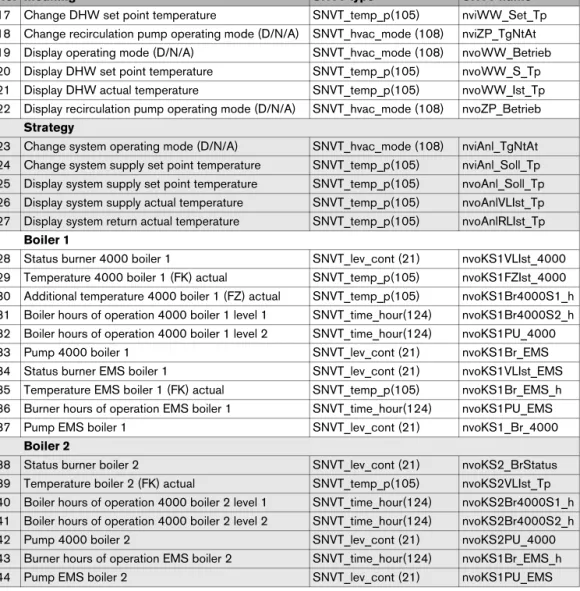
17 Change DHW set point temperature SNVT_temp_p(105) nviWW_Set_Tp 18 Change recirculation pump operating mode (D/N/A) SNVT_hvac_mode (108) nviZP_TgNtAt 19 Display operating mode (D/N/A) SNVT_hvac_mode (108) nvoWW_Betrieb 20 Display DHW set point temperature SNVT_temp_p(105) nvoWW_S_Tp 21 Display DHW actual temperature SNVT_temp_p(105) nvoWW_Ist_Tp 22 Display recirculation pump operating mode (D/N/A) SNVT_hvac_mode (108) nvoZP_Betrieb
Strategy
23 Change system operating mode (D/N/A) SNVT_hvac_mode (108) nviAnl_TgNtAt 24 Change system supply set point temperature SNVT_temp_p(105) nviAnl_Soll_Tp 25 Display system supply set point temperature SNVT_temp_p(105) nvoAnl_Soll_Tp 26 Display system supply actual temperature SNVT_temp_p(105) nvoAnlVLIst_Tp 27 Display system return actual temperature SNVT_temp_p(105) nvoAnlRLIst_Tp
Boiler 1
28 Status burner 4000 boiler 1 SNVT_lev_cont (21) nvoKS1VLIst_4000 29 Temperature 4000 boiler 1 (FK) actual SNVT_temp_p(105) nvoKS1FZIst_4000 30 Additional temperature 4000 boiler 1 (FZ) actual SNVT_temp_p(105) nvoKS1Br4000S1_h 31 Boiler hours of operation 4000 boiler 1 level 1 SNVT_time_hour(124) nvoKS1Br4000S2_h 32 Boiler hours of operation 4000 boiler 1 level 2 SNVT_time_hour(124) nvoKS1PU_4000
33 Pump 4000 boiler 1 SNVT_lev_cont (21) nvoKS1Br_EMS
34 Status burner EMS boiler 1 SNVT_lev_cont (21) nvoKS1VLIst_EMS 35 Temperature EMS boiler 1 (FK) actual SNVT_temp_p(105) nvoKS1Br_EMS_h 36 Burner hours of operation EMS boiler 1 SNVT_time_hour(124) nvoKS1PU_EMS
37 Pump EMS boiler 1 SNVT_lev_cont (21) nvoKS1_Br_4000
Boiler 2
38 Status burner boiler 2 SNVT_lev_cont (21) nvoKS2_BrStatus 39 Temperature boiler 2 (FK) actual SNVT_temp_p(105) nvoKS2VLIst_Tp 40 Boiler hours of operation 4000 boiler 2 level 1 SNVT_time_hour(124) nvoKS2Br4000S1_h 41 Boiler hours of operation 4000 boiler 2 level 2 SNVT_time_hour(124) nvoKS2Br4000S2_h
42 Pump 4000 boiler 2 SNVT_lev_cont (21) nvoKS2PU_4000
43 Burner hours of operation EMS boiler 2 SNVT_time_hour(124) nvoKS1Br_EMS_h
44 Pump EMS boiler 2 SNVT_lev_cont (21) nvoKS1PU_EMS
No. Meaning SNVT type SNVT name
Boiler 3
45 Status burner boiler 3 SNVT_lev_cont (21) nvoKS3_BrStatus 46 Temperature boiler 3 (FK) actual SNVT_temp_p(105) nvoKS3VLIst_Tp 47 Boiler hours of operation 4000 boiler 3 level 1 SNVT_time_hour(124) nvoKS3Br4000S1_h 48 Boiler hours of operation 4000 boiler 3 level 2 SNVT_time_hour(124) nvoKS3Br4000S2_h
49 Pump 4000 boiler 3 SNVT_lev_cont (21) nvoKS3PU_4000
50 Burner hours of operation EMS boiler 3 SNVT_time_hour(124) nvoKS3Br_EMS_h
51 Pump EMS boiler 3 SNVT_lev_cont (21) nvoKS3PU_EMS
Boiler 4
52 Status burner boiler 4 SNVT_lev_cont (21) nvoKS4_BrStatus 53 Temperature boiler 4 (FK) actual SNVT_temp_p(105) nvoKS4VLIst_Tp 54 Boiler hours of operation 4000 boiler 4 level 1 SNVT_time_hour(124) nvoKS4Br4000S1_h 55 Boiler hours of operation 4000 boiler 4 level 2 SNVT_time_hour(124) nvoKS4Br4000S2_h
56 Pump 4000 boiler 4 SNVT_lev_cont (21) nvoKS4PU_4000
57 Burner hours of operation EMS boiler 4 SNVT_time_hour(124) nvoKS4BrEMS_h
58 Pump EMS boiler 4 SNVT_lev_cont (21) nvoKS4PU_EMS
Status
59 Status ECOCAN-BUS SNVT_state(83) nvo_CAN_Adressen
60 Status LON version SNVT_str_asc (36) nvo_LONVersion
No. Meaning SNVT type SNVT name
3.4
Description of the SNVTs for variant 4 boilers
3.4.1 General
Format: YYYY/MM/DD hh:mm:ss
Note:
230 °F (110 °C) is an invalid value (e.g. no temperature sensor connected, sensor defective, etc.)
For the error list, see Chapter 7, page 43.
The current errors are displayed per control panel. Up to 4 errors that occurred at the same time can be displayed. If an error has been eliminated, it disappears from the error list. If more than four errors have occurred, an error not yet eliminated moves up and is displayed.
Error messages are displayed as 2-byte values (2 x 8 bits). The first byte (the first 8 bits seen from the left) displays errors from the control panel of boiler 2. The second byte (the remaining 8 bits) displays errors from the control panel of boiler 1.
Errors that occur are to be interpreted as follows:
Errors are displayed as binary values and must be converted to decimal values. By comparing with the error list (see Chapter 7, page 43), the associated texts are assigned to the error numbers.
0 Time SNVT_time_ stamp(84) nviUhrzeit 7
Tab. 46 Value for comparison of the time in the Buderus control system with the LON network
1 Outdoor temperature SNVT_temp_p(105) nvoAussen_Tp 2
Tab. 47 Display of the current outdoor temperature
2 Error message 1 boiler 1, 2 SNVT_state(83) nvoFehler1_R1_R2 2 3 Error message 2 boiler 1, 2 SNVT_state(83) nvoFehler2_R1_R2 2 4 Error message 3 boiler 1, 2 SNVT_state(83) nvoFehler3_R1_R2 2 5 Error message 4 boiler 1, 2 SNVT_state(83) nvoFehler4_R1_R2 2
Tab. 48 Outputs for error messages 1 (control panel with address 1) and boiler 2 (control panel with address 2)
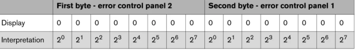
First byte - error control panel 2 Second byte - error control panel 1
Display 0 0 0 0 0 0 0 0 0 0 0 0 0 0 0 0
Interpretation 20 21 22 23 24 25 26 27 20 21 22 23 24 25 26 27
Example: nvoFehler changes On the display, you see:
Boiler 2 has no error. Boiler 1 has a fault with the following error number:
Boiler 1 has the error no. 49 (49 = 1 + 16 + 32), the boiler sensor has a fault
For the error list, see Chapter 7, page 43.
Error messages are displayed as 2-byte values (2 x 8 bits). The first byte (the first 8 bits seen from the left) displays errors from the control panel of boiler 4. The second byte (the remaining 8 bits) displays errors from the control panel of boiler 3. Errors that occur are to be interpreted as follows:
nvoFehler1 0 0 0 0 0 0 0 0 1 0 0 0 1 1 0 0
Tab. 50
nvoFehler1 0 0 0 0 0 0 0 0 1 0 0 0 1 1 0 0
Interpretation 20 21 22 23 24 25 26 27 20 21 22 23 24 25 26 27
Meaning 1 16 32
Tab. 51
6 Error message 1 boiler 3, 4 SNVT_state(83) nvoFehler1_R3_R4 2 7 Error message 2 boiler 3, 4 SNVT_state(83) nvoFehler2_R3_R4 2 8 Error message 3 boiler 3, 4 SNVT_state(83) nvoFehler3_R3_R4 2 9 Error message 4 boiler 3, 4 SNVT_state(83) nvoFehler4_R3_R4 2
Tab. 52 Outputs for error messages of boiler 3 (control panel with address 3) and boiler 4 (control panel with address 4)
First byte - error control panel 2 Second byte - error control panel 1
Display 0 0 0 0 0 0 0 0 0 0 0 0 0 0 0 0
3.4.2 Heating zones
This section describes only heating zone 1.
Format:
Changing the operating mode
With the HVAC_heat / HVAC_off setting, the operating mode for the consumer is changed externally via the LON data bus.
Type of setback:
The type of setback set in the control panel has a direct influence on the behavior of the consumer in setback mode or night mode. The following functions are available for selection:
• Switch off: the heating mode with activation of the pump is turned off entirely with this operating mode, however the frost protection is active.
• Reduced: the controls are set to a lower room temperature set point (night temperature) and they constantly activate the heating pump. The controls work with a parallel heating curve moved downwards depending on the outdoor temperature.
• Outside stop: this operating mode combines the setback mode and the reduced heating mode.
Setting: 36 °F to 84 °F (2 °C to 29 °C) in 1-degree intervals 10 Operating mode (Day/Night/
Auto)
SNVT_hvac_mode (108)
nviHK1TgNtAt 1
Tab. 54 Value for changing the operating mode of a heating zone
Value Designation Description
0 HVAC_AUTO The heating zone is controlled according to the set heating program (automatic mode).
1 HVAC_heat The heating zone is controlled in day mode (manual day mode).
6 HVAC_off The heating zone is controlled in setback mode (manual night mode – see note about setback).
Tab. 55
11 Room set point night temperature
SNVT_temp_p(105) nviHK1RaumSNt_Tp 2
Notes:
• The room set point night temperature specifies the temperature level in the setback mode or night mode for the consumer. With this setting, the heating curve moves in parallel. If you change the room set point temperature by 2 °F (1 °C), then the supply temperature changes by approx. 6 °F (3 °C).
• The room set point night temperature is not active with the setback type "off."
• The room set point night temperature is not taken into account with the setting heating system "constant." The temperature set in the control panel for the heating zone and the temperature setback are active.
Setting: 52 °F to 86 °F (11 °C to 30 °C) in 1-degree intervals Notes:
• The room set point day temperature specifies the temperature level in day mode for the consumer. With this setting, the heating curve moves in parallel. If you change the room set point temperature by 2 °F (1 °C), then the supply temperature changes by approx. 6 °F (3 °C). • The room set point day temperature is not active with the setback type "off."
• The room set point night temperature is not taken into account with the setting heating system "constant." The temperature set in the control panel for the heating zone and the temperature setback are active.
12 Room set point day temperature
SNVT_temp_p(105) nviHK1RaumSTg_Tp 2
Tab. 57 Value for changing the set point temperature for the setback heating mode (day mode)
13 Room set point temperature SNVT_temp_p(105) nviHK1Raum_S_Tp 2
Tab. 58 Display of the currently-valid room set point temperature for the consumer
14 HZ operating mode (D/N/A) SNVT_hvac_mode
(108)
nvoHK1Betrieb 1
Tab. 59 Display of the currently-valid operating mode for the consumer
15 Heating zone supply actual temperature
3.4.3 DHW heating
Format:
Changing the operating mode
With the HVAC_heat / HVAC_off setting, the operating mode for the consumer is changed externally via the LON data bus.
Set range: 86 °F to 140 °F (30 °C to 60 °C) (with approval up to 176 °F (80 °C)); in 1-degree intervals
Notes:
• The set point temperature for DHW heating specifies the temperature level for the consumer in automatic mode or day mode.
• If for DHW heating temperatures > 140 °F (60 °C) are desired, the range up to 176 °F (80 °C) can be released on the service level in the DHW menu.
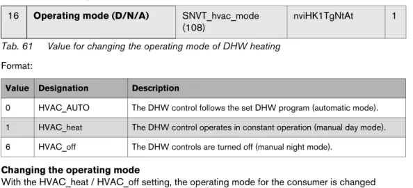
16 Operating mode (D/N/A) SNVT_hvac_mode (108)
nviHK1TgNtAt 1
Tab. 61 Value for changing the operating mode of DHW heating
Value Designation Description
0 HVAC_AUTO The DHW control follows the set DHW program (automatic mode). 1 HVAC_heat The DHW control operates in constant operation (manual day mode). 6 HVAC_off The DHW controls are turned off (manual night mode).
17 DHW set point temperature SNVT_temp_p(105) nviWW_Set_Tp 2
Tab. 62 Value for changing the DHW set point temperature (DHW heating)
WARNING: Risk of scalding at the hot water taps.
There is a risk of scalding at the hot water taps if DHW temperatures can be set above 60 °C and during thermal disinfection.
B Select settings > 140 °F (60 °C) only if a thermostatic mixing valve is installed as protection against scalding.
18 Recirculation pump operating mode (D/N/A)
SNVT_hvac_mode (108)
nviZP_TgNtAt 1
Format:
Changing the operating mode
With the HVAC_heat / HVAC_off setting, the operating mode for the consumer is changed externally via the LON data bus.
Note:
230 °F (110 °C) is an invalid value (e.g. no temperature sensor connected, sensor defective, etc.).
Value Designation Description
0 HVAC_AUTO The activation of the recirculation pump works according to the recirculation pump program set (automatic mode).
1 HVAC_heat The recirculation pump is activated constantly (manual day mode). 6 HVAC_off The recirculation pump is turned off (manual night mode).
19 Operating mode (D/N/A) SNVT_hvac_mode (108)
nvoWW_Betrieb 1
Tab. 64 Display of the currently-valid operating mode for DHW heating
20 DHW set point temperature SNVT_temp_p(105) nvoWW_S_Tp 2
Tab. 65 Display of the currently-valid set point temperature for DHW heating
21 DHW actual temperature SNVT_temp_p(105) nvoWW_Ist_Tp 2
Tab. 66 Display of the actual temperature measured in the DHW tank
22 Recirculation pump operating mode (D/N/A)
SNVT_hvac_mode (108)
nvoZP_Betrieb 1
3.4.4 Strategy
In the "Strategy" section, the values for the entire heating system are summarized. This is especially important for multi-boiler systems (cascades).
Format:
Changing the operating mode
With the HVAC_heat / HVAC_off setting, the operating mode for the consumer is changed externally via the LON data bus.
Set range: 32 °F to 194 °F (0 °C to 90 °C); in 1-degree intervals
Note:
230 °F (110 °C) is an invalid value (e.g. no temperature sensor connected, sensor defective, etc.).
Note:
230 °F (110 °C) is an invalid value (e.g. no temperature sensor connected, sensor defective, etc.).
Note:
230 °F (110 °C) is an invalid value (e.g. no temperature sensor connected, sensor defective, etc.). 23 Operating mode (D/N/A) system SNVT_hvac_mode (108) nviAnl_TgNtAt 2
Tab. 68 Value for changing the operating mode of the entire system (all heating zones)
Value Designation Description
0 HVAC_AUTO The system works according to the internal setting on the control panel (automatic mode). 1 HVAC_heat The system is turned on (all on) and works in manual day mode.
6 HVAC_off The system is turned off (all off).
24 System supply set point temperature
SNVT_temp_p(105) nviAnlVorgabe_Tp 2
Tab. 69 Value for changing the system set point temperature (boiler supply temperature)
25 System supply set point temperature
SNVT_temp_p(105) nvoAnlVLIst_Tp 2
Tab. 70 Display of the currently-valid set point temperature for the boiler system
26 System supply actual temperature
SNVT_temp_p(105) nvoAnlRLIst_Tp 2
Tab. 71 Display of the currently-measured supply temperature for the boiler system
27 System return actual temperature
SNVT_temp_p(105) nvoAnlRLIst_Tp 2
3.4.5 Boiler 1
This section describes "boiler 1."
Burner OFF [0 %] ON [> 0 %] Current output [%]
Note:
230 °F (110 °C) is an invalid value (e.g. no temperature sensor connected, sensor defective, etc.).
Note:
230 °F (110 °C) is an invalid value (e.g. no temperature sensor connected, sensor defective, etc.). 28 Status burner 4000 boiler 1 SNVT_lev_cont (21) nvoKS1_Br_4000 2
Tab. 73 Indicator for boiler 1 with Logamatic 4000 and third party burner
29 Temperature 4000 boiler 1 (FK) actual
SNVT_temp_p(105) nvoKS1VLIst_4000 2
Tab. 74 Display of the current boiler temperature for boiler 1 with Logamatic 4000 and third party burner
30 Additional temperature 4000 boiler 1 (FZ) actual
SNVT_temp_p(105) nvoKS1FZIst_4000 2
Tab. 75 Display of the measured temperature on the additional temperature sensor FZ in the supply of boiler 1 with Logamatic 4000 and third party burner
31 Boiler hours of operation 4000 boiler 1 level 1
SNVT_time_hour(124) nvoKS1Br4000S1_h 2
Tab. 76 Display of the hours of operation for the level 1 (basic load) of boiler 1 with Logamatic 4000 and third party burner
32 Boiler hours of operation 4000 boiler 1 level 2
Pump OFF [0 %] ON [> 0 %] Current output [%]
Burner OFF [0 %] ON [> 0 %] Current output [%]
Note:
230 °F (110 °C) is an invalid value (e.g. no temperature sensor connected, sensor defective, etc.).
Pump OFF [0 %] ON [> 0 %] Current output [%]
33 Pump 4000 boiler 1 SNVT_lev_cont (21) nvoKS1PU_4000 2
Tab. 78 Indicator for boiler 1 with Logamatic 4000 and third party burner
34 Status burner EMS boiler 1 SNVT_lev_cont (21) nvoKS1Br_EMS 2
Tab. 79 Indicator for boiler 1 with Logamatic EMS
35 Temperature EMS boiler 1 (FK) actual
SNVT_temp_p(105) nvoKS1VLIst_EMS 2
Tab. 80 Display of the current boiler temperature for boiler 1 with Logamatic EMS
36 Burner hours of operation EMS boiler 1
SNVT_time_hour(124) nvoKS1Br_EMS_h 2
Tab. 81 Display of the hours of operation for the level 1 (basic load) of boiler 1 with Logamatic EMS
37 Pump EMS boiler 1 SNVT_lev_cont (21) nvoKS1PU_EMS 1
3.4.6 Boiler 2
This section describes "boiler 2." For boilers 3 and 4, the details apply accordingly.
Burner OFF [0 %] ON [> 0 %] Current output [%]
Note:
230 °F (110 °C) is an invalid value (e.g. no temperature sensor connected, sensor defective, etc.).
Pump OFF [0 %] ON [> 0 %]
38 Status burner boiler 2 SNVT_lev_cont (21) nvoKS2_BrStatus 1
Tab. 83 Indicator for boiler with Logamatic EMS or 4000
39 Temperature boiler 2 (FK) actual SNVT_temp_p(105) nvoKS2VLIst_Tp 2
Tab. 84 Display of the current boiler temperature for boiler with Logamatic EMS or 4000
40 Boiler hours of operation 4000 boiler 2 level 1
SNVT_time_hour(124) nvoKS2Br4000S1_h 2
Tab. 85 Display of the hours of operation for the level 1 (basic load) of boiler with Logamatic 4000 and third party burner
41 Boiler hours of operation 4000 boiler 2 level 2
SNVT_time_hour(124) nvoKS2Br4000S2_h 2
Tab. 86 Display of the hours of operation for the modulation/level 2 (large load) of boiler with Logamatic 4000 and third party burner
42 Pump 4000 boiler 2 SNVT_lev_cont (21) nvoKS2PU_4000 1
Tab. 87 Operating message for the boiler circulation pump of the boiler with Logamatic 4000 and third party burner
Pump OFF [0 %] ON [> 0 %] Current output [%]
44 Pump EMS boiler 2 SNVT_lev_cont (21) nvoKS1PU_EMS 1
3.4.7 Status
Using the feedback from the Logamatic control panels, you can get information about whether control panels were turned off, etc.
Status "1" means Logamatic controls are present on the ECOCAN-BUS. Status "0" means Logamatic controls are not present on the ECOCAN-BUS. Example:
In this example, Logamatic controls are connected to the ECOCAN-BUS addresses 1, 2, and 3.
With this variable, information about the LON-Gateway is output.
59 Status ECOCAN-BUS SNVT_state(83) nvo_CAN_Adressen 2
Tab. 90 With these variables, a status report of the ECOCAN-BUS is transmitted to LON
Logamatic controls First byte Second byte
Address (ECOCAN-BUS) 0 1 2 3 4 5 6 7 8 9 10 11 12 13 14 15
Status 0 0 0 0 0 0 0 0 0 0 0 0 0 0 0 0
Logamatic controls First byte Second byte
Address (ECOCAN-BUS) 0 1 2 3 4 5 6 7 8 9 10 11 12 13 14 15
Status 0 1 1 1 0 0 0 0 0 0 0 0 0 0 0 0
60 Status LON version SNVT_str_asc (36) nvo_LONVersion 31
Tab. 91 Information display via the LON-Gateway
1 2 3 4 5 6 7 8 9 1 1 1 1 1 1 1 1 1 1 2 2 2 2 2 2 2 2 2 2 3 0 1 2 3 4 5 6 7 8 9 0 1 2 3 4 5 6 7 8 9 0
4
Operating basics
Fig. 2 Attaching the user interface
Position Operating element/function
1 Button for turning the gateway ON/OFF. 2 Status LED lights up if the gateway is turned on.
3 "ECO-BUS" LED flashes during data transmission via ECO-BUS. 4 "EMS" LED
5 "LON" LED flashes for the successful commissioning of the LON-Gateway. 6 "LON" service button
Tab. 92 Key to Fig. 2
If the EMS LED lights up, there is a communication problem on the ECOCAN-BUS.
5
Incorporation of Logamatic 4000 in LON
networks via Logamatic LON-Gateway
5.1
Structure of the hardware
A main component of the products that communicate via LON data bus such as the Logamatic LON-Gateway is the neuron chip. Each neuron chip has a unique ID, the neuron ID making each device unique. For commissioning, operation, service or replacement, each device is identified via the unique neuron ID. This ensures that no errors take place in communication.
5.2
Creating LON networks
For the creation of networks in which products from various manufacturers communicate via LON data bus, special PC software, a so-called binding tool, is required. For each project, a new database is created and stored separately.
Devices with LON data bus interface are incorporated into this PC software as LON nodes. For this software incorporation, product-specific application files are required. These application files are provided by the manufacturer and contain the product-specific data points, the so-called SNVTs (for details, see Chapter 3). Input network variables (nvi) and output network variables (nvo) of the various products are connected to one another in the PC software. This way, the required functions are created in the PC software.
5.2.1 Commissioning LON networks
The PC software saves the database structure in the respective project. In order to be able to use the functions created in the PC software, the assignment of the functions in the PC software to the device is required. This assignment takes place during "commissioning" via the neuron ID of the device.
During commissioning, a dialog requires the PC software to press the "LON" service button on the LON-Gateway. The LON-Gateway sends a neuron ID to the LON data bus. This neuron ID is registered in the database. From the database of the PC software, the application file is downloaded into the device. This way, the PC software is linked with the hardware (LON-Gateway) on site. This link between software and hardware is called "commissioning."
5.2.2 Decommissioning LON networks
During "decommissioning," a device in the form of a LON node is removed from the network, the neuron ID is deleted from the database of the PC software, and the credit for the neuron ID is released again in the PC software.
For each LON node that is incorporated into this software, license fees in the form of credits are from Echelon. Since the neuron ID is unique, before removing the device, the decommissioning via the PC software is recommended.
6
The LON-Gateway as LonMark object
6.2
Variant 4 boiler
7
Error list
Consec.no.
Error message Consec.
no.
Error message
1 Supply sensor strategy (FVS) fault 28 Function module has no connection fault 2 Outdoor temperature sensor 29 Function module manual OFF fault 3 Heating zone 1 supply sensor fault 30 Internal error no. 1 = internal error no. 30 4 Heating zone 2 supply sensor fault 31 Internal error no. 2 = internal error no. 31 5 Heating zone 3 supply sensor fault 32 Internal error no. 3 = internal error no. 32 6 Heating zone 4 supply sensor fault 33 Internal error no. 4 = internal error no. 33 7 Supply sensor pre-control defective 34 Heating zone 0/5 supply sensor fault 8 DHW sensor fault 35 Heating zone 6 supply sensor fault 9 DHW remains cold 36 Heating zone 7 supply sensor fault 10 Thermal disinfection fault 37 Heating zone 8 supply sensor fault 11 Heating zone 1 remote control fault 38 Heating zone 0 supply sensor fault 12 Heating zone 2 remote control fault 39 Heating zone 0/5 remote control fault 13 Heating zone 3 remote control fault 40 Heating zone 6 remote control fault 14 Heating zone 4 remote control fault 41 Heating zone 7 remote control fault 15 Heating zone 1 communication fault 42 Heating zone 8 remote control fault 16 Heating zone 2 communication fault 43 Heating zone 0 remote control fault 17 Heating zone 3 communication fault 44 Heating zone 0/5 communication fault 18 Heating zone 4 communication fault 45 Heating zone 6 communication fault 19 Magnesium anode used up 46 Heating zone 7 communication fault 20 Fault burner 1 EMS+UBA1 47 Heating zone 8 communication fault 21 Fault burner 2 EMS+UBA1 48 Heating zone 0 communication fault 22 Fault burner 3 EMS+UBA1 49 Boiler supply sensor fault
55 Flue gas sensor defective 81 Address wrong module A fault 56 Flue gas limit exceeded 82 Address unknown module slot 1 fault 57 External fault HK1 83 Address unknown module slot 2fault 58 External fault HK2 84 Address unknown module slot 3 fault 59 External fault HK3 85 Address unknown module slot 4 fault 60 External fault HK4 86 Address unknown module slot A fault 61 External fault HK0/5 87 System return sensor fault (Bottle) 62 External fault HK6 88 DHW inert anode fault
63 External fault HK7 89 DHW external fault input fault
64 External fault HK8 90 Strategy configuration return control fault 65 External fault HK0 91 Strategy configuration supply sensor fault 66 Internal error no. 66 = internal error no. 5 92 Reset
93 Manual switch heating zone 1 67 Internal error no. 67 = internal error no. 6 94 Manual switch heating zone 2 68 Internal error no. 68 = internal error no. 7 95 Manual switch heating zone 3 69 Bus system Ecobus has no reception
fault = internal error no. 8
96 Manual switch heating zone 4
70 Bus system no master (fault) 97 Manual switch heating zone 5 (0/5) 98 Manual switch heating zone 6 71 Bus system address conflict fault 99 Manual switch heating zone 7 72 Address conflict 1 fault 100 Manual switch heating zone 8 73 Address conflict 2 fault 101 DHW manual switch 74 Address conflict 3 fault 102 Manual burner switch 75 Address conflict 4 fault 103 Manual switch for boiler loop 76 Address conflict slot A fault 104 Strategy module missing 77 Address wrong module 1 fault 105 LAP primary pump manual switch 78 Address wrong module 2 fault 106 LAP secondary pump manual switch 79 Address wrong module 3 fault 107 LAP heat exchanger sensor defective 80 Address wrong module 4 fault 108 LAP tank bottom sensor defective
Consec. no.
Error message Consec.
no.
Error message
109 DHW solar sensor defective 137 Heating zone 1 EIB setting fault 110 Collector sensor defective 138 Heating zone 2 EIB setting fault 111 Fault burner 5 EMS+UBA1 139 Heating zone 3 EIB setting fault 112 Fault burner 6 EMS+UBA1 140 Heating zone 4 EIB setting fault 113 Fault burner 7 EMS+UBA1 141 Heating zone 5 EIB setting fault 114 Fault burner 8 EMS+UBA1 142 Heating zone 6 EIB setting fault 115 No connection to burner control 1 143 Heating zone 7 EIB setting fault 116 No connection to burner control 2 144 Heating zone 8 EIB setting fault 117 No connection to burner control 3 145 Heating zone 0 EIB setting fault 118 No connection to burner control 4 146 Heating zone EIB setting fault 119 No connection to burner control 5 147 Blocking error UBA
120 No connection to burner control 6 148 Locking error UBA 121 No connection to burner control 7 149 Solar tank 1 in manual mode 122 No connection to burner control 8 150 Solar tank 2 in manual mode 123 Low-loss header supply sensor fault 151 Heating zone 0 in manual mode fault 124 Boiler 1 3-way valve fault 152 Maintenance required after operating
hours
125 Fill level limit value underrun fault 153 Maintenance required after date 126 Substation heat undersupply 154 DHW is cold
127 Substation supply sensor fault 155 Feed pump in manual mode fault 128 Solar collector sensor fault 156 EMS boiler 1 manual mode 129 Solar bypass return fault 157 EMS boiler 2 manual mode 130 Solar bypass buffer fault 158 EMS boiler 3 manual mode 131 Solar heat quantity supply sensor fault 159 EMS boiler 4 manual mode 132 Solar heat quantity return sensor fault 160 EMS boiler 5 manual mode
Consec. no.
Error message Consec.
no.
165 EMS boiler 2 fault 194 FM458: assignment boiler 2 166 EMS boiler 3 fault 195 FM458: assignment boiler 3 167 EMS boiler 4 fault 196 FM458: assignment boiler 4 168 EMS boiler 5 fault 197 FM458: assignment boiler 5 169 EMS boiler 6 fault 198 FM458: assignment boiler 6 170 EMS boiler 7 fault 199 FM458: assignment boiler 7 171 EMS boiler 8 fault 200 FM458: assignment boiler 8 172 EMS DHW fault 201 FM458: boiler 1 no connection 173 Maintenance required EMS boiler 1 202 FM458: boiler 2 no connection 174 Maintenance required EMS boiler 2 203 FM458: boiler 3 no connection 175 Maintenance required EMS boiler 3 204 FM458: boiler 4 no connection 176 Maintenance required EMS boiler 4 205 FM458: boiler 5 no connection 177 Maintenance required EMS boiler 5 206 FM458: boiler 6 no connection 178 Maintenance required EMS boiler 6 207 FM458: boiler 7 no connection 179 Maintenance required EMS boiler 7 208 FM458: boiler 8 no connection 180 Maintenance required EMS boiler 8 209 FM458: supply sensor strategy 181 FM444 PWE manual switch 210 FM458: return sensor strategy 182 FM444 WE-ON manual switch 211 FM458: configuration of return 183 Sensor heat source return 212 FM458: configuration supply 184 Heat source flow sensor 213 FM458: output for boiler is missing 185 Sensor buffer tank center
186 Sensor buffer tank bottom 187 Sensor buffer tank top 188 Sensor system return 189 Sensor buffer tank center 190 Sensor buffer tank bottom 191 Locking FA heat source 192 Emergency cooling heat source 193 FM458: assignment boiler 1
Consec. no.
Error message Consec.
no.
Error message
Explanation for Tab. 93 EIB (today also KNX1))
1) KNX = Konnex (arose from a combination of EIB with additional bus systems)
= European Installation Bus
EMS = Energy Management System
Remote control = User interface that controls a heating zone, e.g. BFU, BFU/
F
HK = Heating zone
Strategy module or sensor = for multi-boiler systems required control module or
temperature sensor
UBA = Universal burner control unit
For information about troubleshooting, please see the included documentation for the boiler or the control panel.
Bosch Thermotechnology Corp. 50 Wentworth Avenue
Londonderry, NH 03053 Tel. 603-552-1100 Fax 603-584-1681 www.buderus.us U.S.A.
Products manufactured by Bosch Thermotechnik GmbH Sophienstrasse 30-32 D-35576 Wetzlar www.buderus.com
Bosch Thermotechnology Corp. reserves the right to make changes without notice due to continuing