Study Guide
for
Test Technician Test
Test Number: 2774
Human Resources
Performance Assessment Services
Southern California Edison
An Edison International Company
Test_Technician_(2774)
Introduction
The 2774 Test Technician Test is a job knowledge test designed to cover the major knowledge areas necessary to perform the job. This Guide contains strategies to use for taking tests and a study outline, which includes knowledge categories, major job activities, and study references.
Test Session
It is important that you follow the directions of the Test Administrator exactly. If you have any questions about the testing session, be sure to ask the Test Administrator before the testing begins. During testing, you may NOT leave the room, talk, smoke, eat, or drink. Since some tests take several hours, you should consider these factors before the test begins.
All cellular/mobile phones, pagers or other electronic equipment will NOT be allowed in the testing area.
All questions on this test are multiple-choice or hot spot questions. Multiple choice questions have four possible answers. Hot spot questions have a picture, and you must click the correct spot on the picture to answer the question. All knowledge tests will be taken on the computer. For more information on this, please see the next section of this study guide on Computer Based Testing.
The test has a four hour time limit and two parts. When you reach the end of Part I, you will have to submit your answers to reach Part II. You will not be able to change any of your answers from Part I after you press Submit. Once you have submitted Part I, you have the option to take a 10 minute break. If you chose not to take that break, you can proceed directly to Part II by pressing Submit on the break screen.
A scientific calculator will be provided for you to use during the test. The calculator provided during the test session will be one of these models:
Casio fx-250HC,
Texas Instruments TI-30XA, Texas Instruments TI-36X
You will NOT be able to bring or use your own calculator during testing.
You will receive a Test Comment form so that you can make comments about test questions. Write any comments you have and turn it in with your test when you are done.
Study Guide Feedback
At the end of this Guide you have been provided with a Study Guide Feedback page. If a procedure or policy has changed, making any part of this Guide incorrect, your feedback would be appreciated so that corrections can be made.
Test_Technician_(2774)
Computer Based Testing
Taking an SCE knowledge test on the computer is simple. You do not need any computer experience or typing skills. You will only use the keyboard to enter your candidate ID and password. You’ll answer all questions by pressing a single button on the mouse.
Log in Screen
You will be seated at a testing station. When you are seated, the computer will prompt you to enter the candidate ID and password you received in your invitation e-mail. You
MUST have your candidate ID and password or you will be unable to take the test. Once you have confirmed your identity by entering this information, you will see a list of tests available to you.
Sample/Tutorial
Before you start your actual test, a Sample/Tutorial Test is provided to help you become familiar with the computer and the mouse. From the list of exams that appear when you complete the log in, you will select Sample/Tutorial. You will have up to 10 minutes to take the Sample/Tutorial Test. The time you spend on this Sample Test does NOT count toward your examination time. Sample questions are included so that you may practice answering questions. In the Sample/Tutorial Test, you will get feedback on your
answers. You will not receive feedback on your actual test.
Example
During the test, you may see several different types of items. Many of the questions will be multiple choice items. A few items will be pictures, where you’ll have to click the spot on the picture that answers the question. Those picture questions are known as “Hot Spot” questions. More information on each type is below.
Overall Test Information
When you begin the test, you can see the total time allowed for completion displayed at the top of the screen. You can scroll up to see that information at any time during the test.
You can change your answers at any time during the test until the time runs out, or you click the “Submit” button. Once you click Submit, you can not change your answers.
Test_Technician_(2774)
Multiple Choice Questions
To answer each multiple choice question, you should move the mouse pointer over the circle (radio button) next to the answer of your choice, and click the left mouse button. A sample is shown below:
1. In order to answer each question, first read the question and determine the response that best answers the question. Put the mouse pointer directly over the circle corresponding to that response.
2. While the pointer is over the circle corresponding to the best answer, click the left mouse button.
3. The answer you selected should now have a green dot in the circle. If you need to select an alternate answer, simply move the pointer over that circle, and click again.
Test_Technician_(2774)
Hot Spot Questions
To answer each Hot Spot question, you should move the mouse pointer over the part of the image that best answers the question, and click the left mouse button. You will see a pointer appear in that spot. If you want to change your answer, simply move the mouse pointer to a new area on the picture and click again. The pointer will move to the new spot.
A sample is shown below:
1. In order to answer each question, first read the question and determine the place on the image that best answers the question. The pointer that will indicate your answer can always be seen in the bottom left of the image. It looks like this:
Put the mouse pointer directly over the spot on the image you want to select, and click the left mouse button.
Test_Technician_(2774)
2. The pointer will move from the bottom left of the image and appear over the spot you selected.
3. To change your answer, simply move the mouse pointer to the new spot, and click again. The pointer graphic will move to the new spot you’ve selected. In order for your answer to be considered be correct, the center of the pointer ( ) must be over the correct spot on the graphic.
Test_Technician_(2774)
Test Taking Strategies Introduction
The 2774 Test Technician Test contains multiple-choice questions and may also contain hot spot questions. The purpose of this section is to help you to identify some special features of a multiple-choice test and to suggest techniques for you to use when taking one.
Your emotional and physical state during the test may determine whether you are prepared to do your best. The following list provides common sense techniques you can use before the test begins.
Technique Remarks
Be confident - If you feel confident about passing the test, you may lose some of your anxiety.
- Think of the test as a way of demonstrating how much you know, the skills you can apply, the problems you can solve, and your good judgment capabilities.
Be punctual - Arrive early enough to feel relaxed and comfortable before the test begins.
Concentrate - Try to block out all distractions and concentrate only on the test. You will not only finish faster but you will reduce your chances of making careless mistakes.
- If possible, select a seat away from others who might be distracting.
- If lighting in the room is poor, sit under a light fixture.
- If the test room becomes noisy or there are other distractions or irregularities, mention them to the Test Administrator immediately.
Budget your times - Pace yourself carefully to ensure that you will have enough time to complete all items and review your answers.
Test_Technician_(2774)
- Even though the first or second answer choice looks good, be sure to read all the choices before selecting your answer.
Make educated - Make an educated guess if you do not know the answer or
guesses if you are unsure of it.
Changing answers - If you need to change an answer, be sure to erase your previous answer completely. On the computer, be sure that the new answer is selected instead of the old one.
Return to difficult - If particular questions seem difficult to understand, make a
questions note of them, continue with the test and return to them later.
Double-check math - Use scratch paper to double check your
calculations mathematical calculations.
Review - If time permits, review your answers.
- Do the questions you skipped previously.
- Make sure each answer bubble is completely filled in. Erase any stray marks on your answer sheet. When testing on the computer, make sure each multiple choice question has a green dot next to the correct answer. Remember the techniques described in this section are only suggestions. You should follow the test taking methods that work best for you.
Test_Technician_(2774)
Job Knowledge Categories and Study References
Below are the major job knowledge areas (topics) covered on the 2774 Test Technician Test. Listed next to each knowledge category is the number of items on the exam that will measure that topic. You can use this information to guide your studying. Some exams also contain additional pretest items. Pretest items will appear just like all of the other items on your exam, but they will not affect your score. They are an essential part of ensuring the 2774 Test Technician Test remains relevant to successful performance of the job.
There are a total of 98 items on the 2774 Test Technician Test and the passing score is 70%.
A. Electrical Theory (57 items)
Includes AC/DC theory, Ohm's law, circuit diagrams, electrical symbols, 3 phase power theory, and electrical terminology.
B. Electronic Theory (10 items)
Includes basic electronic theory, circuitry, electronic symbols, solid state theory, and knowledge of diodes, rectifiers, transistors, resonance, and oscillators.
C. Mathematics (26 items)
Includes algebra, geometry, trigonometry, phasoring, and other mathematics essential to conducting the standard tests.
D. Test Instruments and Procedures (5 items)
Refer to standard test instruments, and procedures, accuracy requirements and the use of electrical test instruments, meters, and tools.
Study References
The Test Technician Study Guide Workbook (published by SCE Power Production Training) can be found as an appendix to this document.
Important Note: The knowledge categories described below are different from the knowledge categories that appear in the Test Technician Study Guide Workbook provided through SCE PPT. Please refer to the knowledge categories in this guide, not the knowledge categories in the workbook, for relevance to the test.
Study Guide Feedback
Please use this page to notify us of any changes in policies, procedures, or materials affecting this guide. Once completed, return to:
Southern California Edison
Human Resources - Performance Assessment Services G.O. 5, 1st Floor
1515 Walnut Ave. Rosemead, CA 91770
Test Name: 2774 Test Technician Test
Appendix
Test Technician
Study Guide Workbook
N O T I C E
These materials are protected by copyrights. It is illegal to reproduce these training materials or any part of them in any way, to share these materials or to loan or rent them to anyone else without permission.
Copyright © 2010 by Power Production Training Westminster California 92683
All rights reserved
Table of Contents
Study Guide Outline Study References
Math (General Physics) Trigonometry
Laws of Sines and Cosines Electronics
Transformer and Diode Rectifier Circuits Special Purpose Diodes
Ohm’s Law and Power
Introduction to Parallel Circuits Series-Parallel Circuits
Introduction to Kirchhoff’s Law Capacitors and the RC Time Constant Inductors and the L/R Time Constant Inductance and Transformers
Transformers
Study Guide Outline
Job Knowledge Categories
Below are the major job knowledge categories that are covered on the test.
A. Electrical Theory
Includes AC and DC theory, Ohm's law, wiring and circuit diagrams, electrical symbols, 3 phase power theory and electrical terminology
B. Electronic Theory
Includes basic electronic theory, circuitry, electronic symbols, solid state theory, and knowledge of diodes, rectifiers, transistors, resonance, and logic symbols
C. Mathematics
Includes algebra, geometry, trigonometry, and phasoring
D. Test Instruments and Procedures
Refer to standard test procedures and accuracy requirements and the use of electrical test instruments, meters, and tools.
E. Equipment Knowledge
Refers to knowledge of electrical equipment including protective relays, meters, recording instruments, supervisory control
equipment, transformers, voltage regulators, synchronous
condensers, power circuit breakers, carrier current equipment, and other electrical equipment tested by the Test Technician
F. Safety
Includes knowledge of safety procedures, electrical hazards, first aid, fire fighting, and safe operating procedures, including clearance procedures
Study References
Below is a combined listing of the study references for material covered on the test. The materials listed in this Guide are available from public/university libraries, general bookstores, university or technical bookstores. Department reference material (e.g., operating letters, on-line computer systems, etc.) again will depend on
project.
KNOWLEDGE CATEGORY A — ELECTRICAL THEORY
Basic Electricity
Bureau of Navy Personnel, Dover Publications
Delmar’s Standard Textbook of Electricity
Delmar Cengage Learning, by Stephen L. Herman
Vector Analysis
Industrial Press, Stroud and Booth
KNOWLEDGE CATEGORY B — ELECTRONIC THEORY
Basic Solid State Electronics
Van Valkenburgh, Nooger & Neville. Inc Substation Training School
Basic Electronics
Bernard Grob, McGraw Hill Book Co.
Electronic Principles
Albert Paul Malvino, Glencoe Macmillan/McGraw-Hill
KNOWLEDGE CATEGORY C — MATHEMATICS
Basic Mathematics For Electronics
Nelson M. Cooke, McGraw Hill Book Co.
Working with Numbers: Refresher Algebra
Janies T. Shea, STECK-VAUGN
Geometry: A Straightforward Approach
Martin M. Zuckerman, Morton Publishing Co.
Trigonometry the Easy Way
Douglas Downing, Barron's Education Service
KNOWLEDGE CATEGORY D — TEST INSTRUMENTS AND PROCEDURES
Basic Electricity
Bureau of Navy Personnel, Substation Training School
Delmar’s Standard Textbook of Electricity
Math
(General Physics)
Trigonometry
Trigonometry is the study of angles and the relationship between angles and the lines that form them. All trigonometry is based on a right-angled triangle. The most important application of
trigonometry is the solution of triangles based on the sizes of the angles and the lengths of the sides. This lesson explains:
• Sines • Cosines • Tangents
Objectives
After successfully completing this lesson, you will be able to: 1. Define the sine, cosine, and tangent ratios.
2. Graph the sine and cosine functions.
3. Solve triangle problems using trigonometric functions.
Key Words
Sin — Abbreviation of sine. Cos — Abbreviation of cosine.
Sine
The lengths of the sides of a right triangle are related to the size of the angle . This is the basis for trigonometric (trig) functions.
Figure 28. Right Triangle for Trig Functions
The sides of the triangle in Figure 28 are labeled based on the angle about which you are talking, A or (theta) in this case. The side opposite is labeled “a.” The side next to or adjacent to is labeled “b.” The hypotenuse is still called the hypotenuse and is labeled “c.” The angle opposite the hypotenuse, or the right angle (90°), is labeled “C.”
The ratio of the opposite side to the hypotenuse is called the sine of angle . Sine is abbreviated sin.
sin = length of opposite side
length of hypotenuse
or sin = a
c
The reciprocal of sin , the length of the hypotenuse divided by the length of the opposite side, is called the cosecant, or CSC .
If you know any two parts of the sine equation, you can easily calculate the third. If you know the sine of an angle and want to find the angle itself, you can write this as sin-1 or arcsin.
If you calculate the value of sin for various s from 0° to 360°, you could plot them as in Figure 29. This is called a sine curve. Notice that sin is never greater than +1 or less than -1. The values of all trig functions for angles from 0° to 90° have been calculated and are listed in standard trig function tables. As with log tables, fractions of degrees can be interpolated.
Figure 29. Sine Curve
Look at a sample problem: A plank 21 ft. long is used to roll a barrel onto a truck. If the truck bed is 5.9 ft. above the ground, what angle does the plank form with the ground?
Solution: sin = 5 .9 21 = sin-15 .9 21 = sin-1 0.2809
From standard trig tables, or using a calculator with trig functions, sin-1 16.3° = 0.2807, which is very close to 0.2809.
Therefore 16.3°
Cosine
The ratio of the adjacent side to the hypotenuse is called the cosine of . Cosine is abbreviated cos.
cos = length of adjacent side
length of hypotenuse
or cos = b
c
The reciprocal of the cos , the length of the hypotenuse divided by the length of the adjacent side, is called the secant, or sec . See Figure 28, repeated below.
Figure 28. Right Triangle for Trig Functions
The angle whose cosine is known is written cos-1 or arccos.
A plot of cos for from 0° to 360° looks like Figure 30. Notice that cos is never larger than +1 or less than -1.
Figure 30. Cosine Curve
Look at a sample problem: How high will a 35 ft. long ladder reach up a vertical wall if it makes an angle of 18.2° with the wall?
Solution:
cos 18.2° = b
35
b = 35 cos 18.2°
From standard trig tables, or using a calculator with trig functions, cos 18.2° = 0.9500.
b = 35 (0.95) = 33.25 ft.
Tangent
The ratio of the opposite side to the adjacent side is called the tangent of . Tangent is abbreviated tan.
tan = length of opposite side
length of adjacent side
or cos = O
A
The reciprocal of tan , the length of the adjacent side divided by the length of the opposite side, is called the cotangent, or cot . See Figure 28, repeated below.
Figure 28. Right Triangle for Trig Functions
The angle whose tangent is known is written tan-1 or arctan. The
Look at a sample problem: The shadow of a stack is 293 ft. long when the sun is at 41° elevation. Find the height of the stack. Solution:
tan 41° = a
293
a = 293 tan 41°
From standard trig tables, or using a calculator with trig functions, tan 41° = 0.8693.
a = 293 (0.8693) = 254.7 ft.
Laws of Sines and Cosines
The solutions of all triangles can be grouped into cases according to the information given about the angles and sides.
Section 1. Law of Sines
The Law of Sines states that in any triangle ABC, the sides are proportional to the sines of the opposite angles. See Figure 31 for an example of a typical triangle ABC.
Figure 31. Typical Triangle ABC
sin A = d
b sin B =
d a
therefore d = b sin A d = a sin B
Since d = d, it is obvious then that to solve for b: b sin A = a sin B Dividing by sin A b sin A sin A = a sin B sin A b = a sin B sin A Dividing by sin B b sin B = a sin B sin A sin B or b sin B = a sin A
The Law of Sines is normally written as shown below:
a sin A = b sin B = c sin C
Derivations can be obtained from the above relationships as follows: a sin A = b sin B b sin B = c sin C c sin C = a sin A
a sin B = b sin A b sin C = c sin B a sin C = c sin A sin A = a sin B b sin B = bsin C c sin C = c sin A a
Section 2. Law of Cosines
The Law of Cosines states that in any triangle ABC, the square of any side is equal to the sum of the squares of the other two sides diminished by twice the product of the other two sides and the cosine of the included angle. See Figure 31, repeated below. Using the Pythagorean Theorem in the left triangle:
b2 = d2 + (AD)2
Figure 31. Typical Triangle ABC In the triangle on the right side:
sin B = d
a cos B =
DB a
then d = a sin B DB = a cos B
Then AD = AB - DB = c - a cos B
and b2 = d2 + (AD)2 = (a sin B)2 + (c - a cos B)2
or b2 = a2 sin2 B + (c2 -2ac cos B + a2 cos2 B)
b2 = a2 sin2 B + c2 -2ac cos B + a2 cos2 B
b2 = a2 (sin2 B + cos2B) + c2 - 2ac cos B
It can be shown from the Pythagorean Theorem that: (sin2 B + cos2 B) = 1
Therefore: b2 = a2 + c2 - 2ac cos B
The relationships for finding other values can be derived in the above manner to yield:
a2 = b2 + c2 - 2bc cos A
b2 = a2 + c2 - 2ac cos B
c2 = a2 + b2 - 2ab cos C
To determine unknown angles, the above relationships can be manipulated to yield the following equations:
To find angle C: c2 = a2 + b2 - 2ab cos C 0 = a2 + b2 - c2 - 2ab cos C 2ab cos C = a2 + b2 - c2 2 ab cos C 2 ab = a2 b2 c2 2 ab cos C = a 2 b2 c2 2 ab Similarly, cos A = b 2 c2 a2 2 bc cos B = a 2 c2 b2 2 ac
NOTE: In general, the Law of Sines is used when two angles and one side or two sides and an angle opposite one of them are known, while the Law of Cosines is used when two sides and the included angle or three sides are known.
Practice Problems
Use standard trig table functions or, if you have one, a calculator with trig functions, to solve these problems. Answers are at the end of the module.
1. A road makes an angle of 7.4° with the horizontal. Find the increase in elevation (in feet) if you drive one mile. (One mile = 5280 ft.)
2. A 30 ft. ladder is placed against a vertical wall so that the foot of the ladder is 6.5 ft. from the wall. What angle does the ladder make with the ground? How high on the wall does the ladder reach?
3. Given the following, find the angles:
a. arcsin 0.1564 b. arccos 0.301 c. arctan 0.419 d. sin-1 0.0262
4. A platform is 10 ft. above floor level. A ramp is to be built from the floor to the platform. If the ramp is to make an angle with the floor of 14°, how far from the platform must the ramp start? How long must the ramp be?
4. A tower is braced by a cable fastened 15 ft. below the top and to an anchor that is 65 ft. from the base of the tower. If the brace makes an angle of 70° with the ground, how high is the tower?
Transformer and Diode
Rectifier Circuits
A rectifier diode is ideally a closed switch when forward-biased and an open switch when reverse-biased. Because of this, it is useful for converting alternating current to direct current. This chapter discusses three basic rectifier circuits called the half-wave rectifier, the full-wave rectifier, and the bridge rectifier.
The Input Transformer
Power companies in the United States supply a nominal line voltage of 115 V rms at a frequency of 60 Hz. The actual voltage coming out of a power outlet may vary from 105 V to 125 V rms, depending on the time of day, locality, and other factors. Recall that the relation between the rms value and the peak value of a sine wave is given by
Vrms = 0.707Vp (4-1)
This equation says that the rms voltage equals 70.7 percent of the peak voltage. Recall what rms value means. This is the equivalent dc voltage that would produce the same amount of power over one complete cycle.
Basic Equation
Line voltage is too high for most of the devices used in electronics equipment. This is why a transformer is commonly used in almost all electronics equipment. This transformer steps the ac voltage
down to lower levels that are more suitable for use with devices like diodes and transistors.
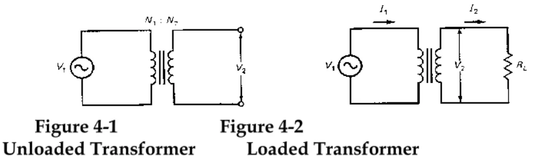
Figure 4-1 shows an example of a transformer. The left coil is called the primary winding and the right coil is called the secondary
winding. The number of turns on the primary winding is N1, and the
number of turns on the secondary winding is N2. The vertical lines
between the primary and secondary windings indicate that the turns are wrapped on an iron core.
Figure 4-1 Figure 4-2
Unloaded Transformer Loaded Transformer
With this type of transformer, the coefficient of coupling k
approaches one, which means tight coupling exists. In other words, all the flux produced by the primary winding cuts through the secondary winding. The voltage induced in the secondary winding is given by V N N V 2 2 1 1 (4-2)
The voltages in this equation may be either rms or peak voltages. Just be consistent and use rms for both, or peak for both.
Step-Up Transformer
When the secondary winding has more turns than the primary winding, more voltage is induced in the secondary than in the primary. In other words, when N2/N1 is greater than one, the
transformer is referred to as a step-up transformer. If N1 = 100
turns and N2 = 300 turns, the same flux cuts through three times as
many turns in the secondary as in the primary winding. This is why the secondary voltage is three times as large as the primary voltage.
Step-Down Transformer
When the secondary winding has fewer turns than the primary winding, less voltage is induced in the secondary than in the
primary. In this case, the turns ratio, N2:N1, is less than one, and the
transformer is called a step-down transformer. If N1 = 100 turns
the secondary as in the primary winding, and the secondary voltage is half the primary voltage.
Effect on Current
Figure 4-2 shows a load resistor connected across the secondary winding. Because of the induced voltage across the secondary winding, a current exists. If the transformer is ideal (k = 1 and no power is lost in the windings or the core), the output power equals the input power:
P2 = P1
or
V2I2 = V1I1
We can rearrange the foregoing equation as follows:
I I V V 1 2 2 2
But Eq. (4-2) implies that V2/V1 = N2/N1. Therefore,
I1 I2 N2 N1 or I N N I 1 2 1 2 (4-3)
An alternative way to write the foregoing equation is
I N N I 2 1 2 1 (4-4)
Notice the following. For a step-up transformer, the voltage is stepped up but the current is stepped down. On the other hand, for a step-down transformer, the voltage is stepped down but the current is stepped up.
Example 4–1
Suppose the voltage from a power outlet is 120 V rms. What is the peak voltage?
Solution
Using algebra, we can rewrite Eq. (4-1) in this equivalent form:
V p Vr m s
0 7 0 7.
Now, substitute the rms voltage and calculate the peak voltage:
V p 1 2 0 0 7 0 7 1 7 0 V V .
This tells us that the sinusoidal voltage out of the power outlet has a peak value of 170 V.
Example 4–2
A step-down transformer has a turns ratio of 5:1. If the primary voltage is 120 V rms, what is the secondary voltage?
Solution
Divide the primary voltage by 5 to get the secondary voltage:
V2 1 2 0 5 2 4 V V Example 4–3
Suppose a step-down transformer has a turns ratio of 5:1. If the secondary current is 1 A rms, what is the primary current?
Solution With Eq. (4-3), I1 1 5 0 2 A A .
As a check on this answer, use your common sense as follows, This is a step-down transformer, which means the current is stepped up going from primary to secondary, equivalent to saying the current is stepped down as we go from the secondary to the primary. This means the primary current is five times smaller than the secondary current. Whenever possible, you should check that your answers are logical because it is easy to make a mistake with equations.
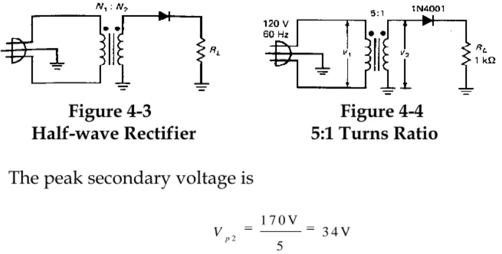
The Half-Wave Rectifier
The simplest circuit that can convert alternating current to direct current is the half-wave rectifier, shown in Fig. 4-3. Line voltage from an ac power outlet is applied to the primary winding of the transformer. Usually, the power plug has a third prong to ground the equipment. Because of the turns ratio, the peak voltage across the secondary winding is
V N N V p2 p 2 1 1
Recall the dot convention used with transformers. The dotted ends of a transformer have the same polarity of voltage at any instant in time. When the upper end of the primary winding is positive, the upper end of the secondary winding is also positive. When the upper end of the primary winding is negative, the upper end of the secondary winding is also negative.
Here is how the circuit works. On the positive half cycle of primary voltage, the secondary winding has a positive half sine wave across it. This means the diode is forward-biased. However, on the
negative half cycle of primary voltage, the secondary winding has a negative half sine wave. Therefore, the diode is reverse-biased. If you use the ideal-diode approximation for an initial analysis, you will realize that the positive half cycle appears across the load resistor, but not the negative half cycle.
For instance, Fig. 4-4 shows a transformer with a turns ratio of 5:1. The peak primary voltage is
Vp1 1 2 0 0 7 0 7 1 7 0 V V .
Figure 4-3 Figure 4-4 Half-wave Rectifier 5:1 Turns Ratio
The peak secondary voltage is
Vp2
5 1 7 0 V
3 4 V
With the ideal-diode approximation, the load voltage has a peak value of 34 V.
Figure 4-5 shows the load voltage. This type of waveform is called half-wave signal because the negative half cycles have been clipped off or removed. Since the load voltage has only a positive half cycle, the load current is unidirectional, meaning that it flows only in one direction. Therefore, the load current is a pulsating direct current. It starts at zero at the beginning of the cycle, then increases to a
maximum value at the positive peak, then decreases to zero where it sits for the entire negative half cycle.
Figure 4-5 Half-wave Signal
Period
The frequency of the half-wave signal is still equal to the line frequency, which is 60 Hz. (In Europe, line frequency is 50 Hz.) Recall that the period, T, equals the reciprocal of the frequency. Therefore, the half-wave signal has a period of
T f
1 1
6 0 H z
0 .0 1 6 7 s 1 6 .7 m s
This is the amount of time between the beginning of a positive half cycle and the start of the next positive half cycle. This is what your
would measure if you looked at a half-wave signal with an oscilloscope.
DC or Average Value
If you connect a dc voltmeter across the load resistor of Figure 4-5, it will indicate a dc voltage of Vp/ , which may be written as
Vdc = 0.318Vp (4-5)
where Vpis the peak value of the half-wave signal across the load
resistor. For instance, if the peak voltage is 34 V, the dc voltmeter will read
Vdc= 0.318(34 V) = 10.8 V
This dc voltage is sometimes called the “average” value of the half-wave signal because the voltmeter reads the average voltage over one complete cycle. The needle of the voltmeter cannot follow the rapid variations of the half-wave signal, so the needle settles down on the average value, which is 31.8 percent of the peak value. (The 31.8 percent can be proved with calculus.)
Approximations
Because the secondary voltage is much greater than the knee voltage, using the second approximation will improve the analysis only slightly. If we use the second approximation, the half-wave signal has a peak of 33.3 V. Furthermore, since the bulk resistance of a 1N4001 is only 0.23 compared to a load resistance of 1 k , there is no increase in accuracy when using the third
approximation. In conclusion, either the ideal diode or the second approximation is adequate in analyzing this circuit.
Example 4–4
In Europe, a half-wave rectifier has an input voltage of 240 V rms with a frequency of 50 Hz. If the step-down transformer has a turns ratio of 8:1, what is the load voltage?
Solution
You can divide 240 V by 0.707 to get the answer. Here is an alternative way to get the peak voltage. Since the rms voltage is twice as large as previous examples, the peak voltage is twice as large as before:
Vpl = 2(170 V) = 340 V
Because of the 8:1 step down, the secondary voltage has a peak value of
Vp2
8 3 4 0 V
4 2 .5 V
Ignoring the diode drop means that the load voltage is a half-wave signal with a peak value of 42.5 V.
The period of the rectified output voltage is slightly longer:
T 1
5 0 H z
0 .0 2 s 2 0 m s
This is what you would measure with an oscilloscope.
The Full-Wave Rectifier
Figure 4-6 shows a “full-wave rectifier.” Notice the grounded center tap on the secondary winding. Because of this center tap, the circuit is equivalent to two half-wave rectifiers. The upper rectifier handles the positive half cycle of secondary voltage, while the lower rectifier handles the negative half cycle of secondary voltage. In other words, D1 conducts on the positive half cycle and D2
conducts on the negative half cycle. Because of this, the rectified load current flows during both half cycles. Furthermore, this load current flows in one direction only.
Figure 4–6 Full-wave Rectifier
For instance, Fig. 4-7 shows a transformer with a turns ratio of 5:1. The peak primary voltage is still equal to
Figure 4–7
Example of Full-wave Rectifier
Vp1 1 2 0 V
0 .7 0 7
1 7 0 V
The peak secondary voltage is
Vp2 1 7 0 V
5
3 4 V
Because of the grounded center tap, each half of the secondary winding has a sinusoidal voltage with a peak of only 17 V. Therefore, the load voltage has an ideal peak value of only 17 V instead of 34 V. This factor- of-two reduction is a characteristic of all full-wave rectifiers. It is a direct result of using a grounded center tap on the secondary winding.
Figure 4-8 shows the load voltage. This type of waveform is called a full-wave signal. It is equivalent to inverting or flipping the
negative half cycles of a sine wave to get positive half cycles. Because of Ohm's law, the load current is a full-wave signal with a peak value of Ip 1 7 V k 1 7 m A 1 Figure 4–8 Full-wave Signal
DC or Average Value
If you connect a dc voltmeter across the load resistor of Fig. 4-7, it will indicate a dc voltage of 2Vp/ , which is equivalent to
Vdc = 0.636Vp (4-6)
where Vp is the peak value of the half-wave signal across the load
resistor. For instance, if the peak voltage is 17 V, the dc voltmeter will read
Vdc = 0.636(17 V) = 10.8 V
This dc voltage is the average value of the full-wave signal because the voltmeter reads the average voltage over one complete cycle.
Output Frequency
The frequency of the full-wave signal is double the input frequency. Why? Recall how a complete cycle is defined. A waveform has a complete cycle when it repeats. In Fig. 4-8, the rectified waveform begins repeating after one half cycle of the primary voltage. Since line voltage has a period, T1, of
T f 1 1 1 6 0 H z 0 .0 1 6 7 s 1 6 .7 m s
The rectified load voltage has a period, T2, of T2 1 6 .7 m s
2
8 .3 3 m s
The frequency of the load voltage therefore equals
f T 2 2 1 1 8 .3 3 m s 1 2 0 H z
This says the output frequency equals two times the input frequency. In symbols,
fo u t 2fin (4-7)
This doubling of the frequency is a characteristic of all full-wave rectifiers. It is a direct result of using two diodes, one to rectify the positive half cycle of input voltage and the other to rectify the
negative half cycle of input voltage. Visually, the effect is to invert the negative half of the input voltage to get a full-wave signal. Again, notice the following about the use of diode approximations. Because the secondary voltage is much greater than the knee
voltage, the second approximation results in a full-wave output voltage with a peak value of 16.3 V instead of 17 V, Once more, the small bulk resistance of a 1N4001 has almost no effect. In
conclusion, either the ideal diode or the second approxima-tion is adequate in analyzing most full-wave circuits. The only time you would consider using the third approximation is when the load resistance is small.
Example 4–5
Suppose the full-wave rectifier of Fig, 4-7 has an input voltage of 240 V rms with a frequency of 50 Hz. If the step-down transformer has a turns ratio of 8:1, what is the load voltage?
Solution
The peak primary voltage is the same as the previous example::
Vp1 3 4 0 V
The peak secondary voltage has the same peak value as before:
Vp2 4 2 .5 V
The center tap reduces this voltage by a factor of 2. In other words, the entire secondary winding has a sine wave across it with a peak value of 42.5 V. Therefore, each half of the secondary winding has a sine wave with only half this peak value, or approximately 21.2 V. Ignoring the diode drop means that the load voltage is a full-wave signal with a peak value of 21.2 V.
Also, the rectified output signal has a frequency of twice the input frequency. In this case, the output frequency is
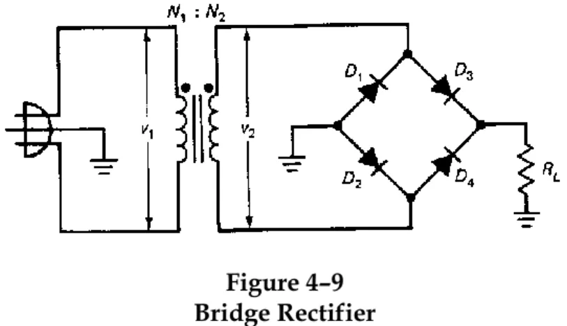
The Bridge Rectifier
Figure 4-9 shows a bridge rectifier. By using four diodes instead of two, this clever design eliminates the need for a grounded center tap. The advantage of not using a center tap is that the rectified load voltage is twice what it would be with the full-wave rectifier.
Figure 4–9 Bridge Rectifier
Here is how it works. During the positive half cycle of line voltage, diodes D2 and D3 conduct; this produces a positive half cycle across
the load resistor. During the negative half cycle of line voltage, diode D1 and D4 conduct; this produces another positive half cycle
across the load resistor. The result is a full-wave signal across the load resistor.
For instance, Fig. 4-10 shows a transformer with a turns ratio of 5:1. The peak primary voltage is still equal to
Vp1 1 2 0 V
0 .7 0 7
1 7 0 V
Figure 4–10
Figure 4-11 Full-wave Signal The peak secondary voltage is still
Vp2 1 7 0 V
5
3 4 V
Because the full secondary voltage is applied to the conducting diodes in series with the load resistor, the load voltage has an ideal peak value of 34 V, twice that of the full-wave rectifier discussed earlier.
Figure 4-11 shows the ideal load voltage. As you see, the shape is identical to that of a full-wave rectifier. Therefore, the frequency of the rectified signal equals 120 Hz, twice the line frequency. Because of Ohm's law, the load current is a full-wave signal with a peak value of
Ip 34V
1k 34mA
There is a new factor to consider when using the second
approximation with a bridge rectifier: there are two conducting diodes in series with the load resistor during each half cycle, Therefore, we must subtract two diode drops instead of only one, This means the peak voltage with the second approximation is
Vp, = 34 V - 2(0.7 V) = 32.6 V
The additional voltage drop across the second diode is one of the few disadvantages of the bridge rectifier, Also, there are two bulk resistances in series with the load resistance. But the effect is again negligible with the circuit values shown in Fig, 4-10. Unless you are designing a bridge rectifier, you will not normally use the third approximation because the bulk resistance is usually much smaller than the load resistance.
Most designers feel that having two diode drops and two bulk resistances is only a minor disadvantage. The advantages of the bridge rectifier include a full-wave output, an ideal peak voltage equal to the peak secondary voltage, and no center tap on the secondary winding. These advantages have made the bridge rectifier the most popular rectifier design. Most equipment uses a bridge rectifier to convert the ac line voltage to a dc voltage suitable for use with semiconductor devices.
Example 4–6
Suppose the bridge rectifier of Fig. 4-9 has an input voltage of 240 V rms with a frequency of 50 Hz. If the step-down transformer has a turns ratio of 8:1, what is the load voltage?
Solution
The peak primary voltage is the same as the previous example:
Vp1 340V
The peak secondary voltage has the same peak value as before:
Vp2 4 2 .5 V
This time, the entire secondary voltage is across two conducting diodes in series with the load resistor. Ignoring the diode drop means that the load voltage is a full-wave signal with a peak value of 42.5 V. Also, the frequency of the rectified output voltage is 100 Hz.
The Capacitor-Input Filter
The load voltage out of a rectifier is pulsating rather than steady. For instance, look at Fig. 4-11. Over one complete output cycle, the load voltage increases from zero to a peak, then decreases back to zero. This is not the kind of dc voltage needed for most electronic circuits. What is needed is a steady or constant voltage similar to what a battery produce. To get this type of rectified load voltage, we need to use a “filter.”
Half-wave Filtering
The most common type of filter is the capacitor-input filter shown in Fig. 4-12. To simplify the initial discussion of filters, we have
represented an ideal diode by a switch. As you can see, a capacitor has been inserted parallel with the load resistor. Before the power is turned on, the capacitor is uncharged; therefore, the load voltage is zero. During the first quarter cycle of the secondary voltage, the diode is forward-biased. Ideally, it looks like a closed switch. Since the diode connects the secondary winding directly across the capacitor, the capacitor charges to the peak voltage, Vp.
Figure 4–12 Capacitor-input Filter
Just past the positive peak, the diode stops conducting, which means the switch opens. Why? Because the capacitor has Vp. volts
across it. Since the secondary voltage is slightly less than Vp, the
diode goes into reverse bias. With the diode now open, the
capacitor discharges through the load resistance. But here is the key idea behind the capacitor-input filter: by deliberate design, the discharging time constant (the product of RL and C) is much greater
than the period, T, of the input signal. Because of this, the capacitor will lose only a small part of its charge during the off time of the diode as shown in Fig. 4-13a.
Figure 4–13
When the source voltage again reaches its peak, the diode conducts briefly and recharges the capacitor to the peak voltage. In other words, after the capacitor is initially charged during the first quarter cycle, its voltage is approximately equal to the peak
secondary voltage. This is why the circuit is sometimes called a peak detector.
The load voltage is now almost a steady or constant dc voltage. The only deviation from a pure dc voltage is the small ripple caused by charging and discharging the capacitor. The smaller the ripple is, the better. One way to reduce this ripple is by increasing the discharging time constant, which equals RLC.
Full-Wave Filtering
Another way to reduce the ripple is to use a full-wave rectifier or bridge rectifier; then the ripple frequency is 120 Hz instead of 60 Hz. In this case, the capacitor is charged twice as often and has only half the discharge time (see Fig. 4-13b). As a result, the ripple is smaller and the dc output voltage more closely approaches the peak voltage. From now on, our discussion will emphasize the bridge rectifier driving a capacitor-input filter because this is the most commonly used circuit.
Brief Conduction of Diode
In the unfiltered rectifiers discussed earlier, each diode conducts for half a cycle. In the filtered rectifiers we are now discussing, each diode conducts for much less than half a cycle. When the power switch is first turned on, the capacitor is uncharged. Ideally, it takes only a quarter of a cycle to charge the capacitor to the peak
secondary voltage. After this initial charging, the diodes turn on only briefly near the peak and are off during the rest of the cycle. In terms of degrees, the diodes turn on for only a couple of degrees during each cycle (half a cycle is 1 8 0 ) .
An Important Formula
Whether you are troubleshooting, analyzing, or designing, you have got to know how to estimate the size of the ripple. Normally, the ripple is small compared to the peak secondary voltage. For most applications, the ripple is considered small when it is less than 10 percent of the load voltage. For instance, if the load voltage is I5 V, the ripple in most filtered rectifiers will be less than 1.5 V peak-to-peak.
Here is the formula for ripple expressed in terms of easily measured circuit values:
V I
f
R
C (4-8)
where VR = peak-to-peak ripple voltage
I = dc load current
f = ripple frequency
C = capacitance
The proof of Eq. (4-8) is too lengthy and complicated to show in this book. But the derivation assumes that the peak-to-peak ripple is less than 20 percent of the load voltage. Beyond this point, you cannot use Eq. (4-8) without encountering a lot of error. But as was already discussed earlier, the whole point of the capacitor-input filter is to produce a steady or constant dc voltage. For this reason, most designers deliberately select circuit values to keep the ripple less than 10 percent of the load voltage. In the circuits you
encounter, you will find that the ripple is usually less than 10 percent of the load voltage.
DC Voltage
To be successful in electronics, you have to learn the following basic idea: approximations are the rule, not the exception. Why? Because electronics is not an exact science like pure mathematics. The idea that you must always get exact answers is a false idea, a left-brain trap. For most of the work in electronics, approximate answers are adequate and even desirable.
The situation is like an artist painting a picture. The best artist starts with the largest brush when beginning a painting. The artist then switches to a medium-sized brush to improve the picture, and, finally, may use the smallest brush to get the finest detail. No good artist ever uses a small brush all of the time.
The three diode approximations are like an artist’s brushes. You should start with the ideal diode to get the big picture. In many cases (trouble shooting, for instance), this will be all you need. Often, you will want to improve your analysis by using the second approximation (a lot of everyday work is done with this one).
Finally, the third approximation may be best in some situations (if the circuit uses 1 percent resistors, for example).
First Approximation
With the foregoing in mind, here is how the diode approximations affect the value of the load voltage. For an ideal diode and no ripple, the dc load voltage out of a filtered bridge rectifier equals the peak secondary voltage:
Vd c Vp2
This is what you want to remember when you are trouble-shooting or making a preliminary analysis of a filtered bridge rectifier.
Second Approximation
With the second approximation of a diode, we have to allow for the 0.7 V across each diode. Since there are two conducting diodes in series with the load resistor, the dc load voltage with no ripple out of a filtered bridge rectifier is
Vd c Vp2 1 .4 V
Third Approximation
In the third approximation, two bulk resistances are in the charging path of the capacitor. This complicates the analysis because the diode conducts briefly only near the peak. Fortunately, bulk
resistances of rectifier diodes are typically less than 1 . Because of
this, they usually have little or no effect on the load voltage. Unless you are designing a filtered bridge rectifier, you will not need to consider the effect of bulk resistance. (If you are designing the circuit, you will need to use advanced mathematics because you have to deal with an exponential function. The alternative is to build the circuit and arrive at circuit values by experiment. The main rule here is to keep the load resistance as large as possible compared to the bulk resistance.)
There is one more improvement that we can use. We can include the effect of the ripple as follows:
Vd c(w ith r ip p le) Vd c w ith o u tr ip p le( ) VR
2
The idea here is to subtract half the peak-to-peak ripple to refine the answer slightly. Since peak-to-peak is usually less than 10 percent, the improvement in the answer is less than 5 percent.
A Basic Guideline
The resistors used in typical electronic circuits have tolerances of 5 percent. Sometimes, you will see precision resistors of 1 percent used in critical applications. And sometimes, you will see resistors of 10 percent used. But if we take 5 percent as the usual tolerance, then one guideline for selecting an approxima-tion is this: Ignore a quantity if it produces an error of less than 5 percent. This means we can use the ideal diode if it produces less than 5 percent error. If the ideal diode results in 5 percent or more error, switch to the second approximation. Also, ignore the effect of ripple when it is less than 10 percent of the load voltage. (Remember: the peak-to-peak ripple is divided by two before subtracting from the load voltage. Therefore, a 10 percent ripple produces only a 4 percent error in load voltage.)
The foregoing guideline will be of some help in deciding which approximation to use, but don't lean on this guideline too heavily. You may have a situation where a 5 percent guideline is not suitable, Remember the artist's brushes. The job may require a smaller or larger brush. It is impossible to give you a rule for every situation because real life is too messy and has too many
exceptions. But don't be discouraged. That's what makes electronics more interesting than accounting. Use the basic guideline given here, but be ready to abandon it if you feel it doesn't apply to your situation.
Example 4–7
Suppose a bridge rectifier has a dc load current of 10 mA and a filter capacitance of 470 F. What is the peak-to-peak ripple out of a capacitor-input filer?
Solution
Use Eq. ( 4-8) to get
VR 1 0 m A
1 2 0 H z ) ( 4 7 0 F
0 .1 1 7 V
( )
This assumes the input frequency is 60 Hz,. which is the normal line frequency in the United States.
Example 4–8
Assume we have a filtered bridge rectifier with a line voltage of 120 V rms, a turns ratio of 9.45, a filter capacitance of 470 F, and a load resistance of 1 k . What is the dc load voltage?
Solution
Start by calculating the rms secondary voltage:
V2 1 2 0 V
9 .4 5
1 2 .7 V
This is what you would measure with an ac voltmeter connected across the secondary winding.
Next, calculate the peak secondary voltage:
Vp2 1 2 .7 V
0 .7 0 7
1 8 V
With an ideal diode and ignoring the ripple, the dc load voltage equals the peak secondary voltage:
Vd c 1 8 V
This answer would be adequate if you were troubleshooting a circuit like this. The dc load voltage is the approximate value you would read with a dc voltmeter across the load resistor. If there were trouble in such a circuit, the dc voltage probably would be much lower than 18 V.
The second approximation improves the answer by including the effect of the two-diode voltage drops:
Vd c 1 8 V 1 .4 V 1 6 .6 V
This is more accurate, so let us use it in the remaining calculations. To calculate the ripple, we need the value of dc load current:
I k
1 6 .6 V
1 6 .6 m A
1
V F R 1 6 .6 m A 1 2 0 H z ) ( 4 7 0 0 .2 9 4 V ( )
This is the peak-to-peak ripple and is what you would see if you looked at the load voltage with the ac input of an oscilloscope. This ripple has little effect on the dc load voltage:
V ( w i t h r i p p l e ) = 1 6 .6 - 0 .2 9 4 V 2
1 6 .5 V d c
This gives you the basic idea of how to calculate the dc load voltage and ripple.
Voltage Multipliers
A voltage multiplier is two or more peak detectors or peak rectifiers that produce a dc voltage equal to a multiple of the peak input voltage (2Vp,3Vp,4Vp,and so on). These power supplies are used for
high voltage/low current devices like cathode-ray tubes (the picture tubes in TV receivers, oscilloscopes, and computer displays).
Half-Wave Voltage Doubler
Figure 4-15a is a voltage doubler. At the peak of the negative half cycle, D1 is forward-biased and D2 is reverse-biased. Ideally, this
charges C1 to the peak voltage, Vp, With the polarity shown in Fig.
4-15b. At the peak of the positive half cycle, D1 is reverse-biased
and D2 is forward-biased. Because the source and C1 are in series, C2
Will try to charge toward 2Vp. After several cycles, the voltage
across C2 Will equal 2Vp, as shown in Fig. 4-15c.
By redrawing the circuit and connecting a load resistance, we get Fig. 1-15d. Now it's clear that the final capacitor discharges through the load resistor. As long as RL is large, the output voltage equals
2Vp (ideally). That is, provided the load is light (long time
constant), the output voltage is double the peak input voltage. This input voltage normally comes from the secondary winding of a transformer.
For a given transformer, you can get twice as much output voltage as you get from a standard peak rectifier. This is useful when you are trying to produce high voltages (several hundred volts or more). Why? Because higher secondary voltages result in bulkier transformers. At some point, a designer may prefer to use voltage doublers instead of bigger transformers.
The circuit is called a half-wave doubler because the output capacitor, C2, is charged only once during each cycle. As a result,
the ripple frequency is 60 Hz. Sometimes you will see a surge resistor in series with C1.
Figure 4-15
Half-wave Voltage Doubler
Figure 4-16
Full-wave Voltage Doubler
Full-Wave Voltage Doubler
Figure 4-16 shows a full-wave voltage doubler. On the positive half cycle of the source, the upper capacitor charges to the peak voltage with the polarity shown. On the next half cycle, the lower capacitor
charges to the peak voltage with the indicated polarity. For a light load, the final output voltage is approximately 2Vp.
The circuit is called a full-wave voltage doubler because one of the output capacitors is being charged during each half cycle. Stated another way, the output ripple is 120 Hz. This ripple frequency is an advantage because it is easier to filter. Another advantage of the full-wave doubler is that the PIV rating of the diodes need only be greater than Vp.
The disadvantage of a full-wave doubler is the lack of a common ground between input and output. In other words, if we ground the lower end of the load resistor in Fig. 4-16, the source is Floating. In the half- wave doubler of Fig. 4-15d, grounding the load resistor also grounds the source, an advantage in some applications.
Study Aids
The following study aids will help to reinforce the ideas discussed in this chapter. For best results, use these study aids within 6 hours of reading the earlier material. Then review these study aids a week later and a month later to ensure that the concepts remain in your long-term memory.
Summary
Sec. 4-1 The Input Transformer
The input transformer is usually a step-down transformer. In this type of transformer, the voltage is stepped down and the current is stepped up. One way to remember this is by remem-bering that the output power equals the input power in a lossless transformer.
Sec. 4-2 The Half-wave Rectifier
The half-wave rectifier has a diode in series with a load resistor. The load voltage is a half-wave rectified sine wave with a peak value approximately equal to the peak secondary voltage. The dc or average load voltage equals 31.8 percent of the peak load voltage.
See. 4-3 The Full-wave Rectifier
The full-wave rectifier has a center-tapped transformer with two diodes and a load resistor. The load voltage is a full-wave rectified sine wave with a peak value approximately equal to half of the peak Secondary voltage. The dc or average load voltage equals 63.6 percent of the peak load voltage. The ripple frequency equals two times the input frequency.
See. 44 The Bridge Rectifier
The bridge rectifier has four diodes. The load voltage is a full-wave rectified sine wave with a peak value approximately equal to peak secondary voltage. The de or average load voltage equals 63.6 percent of the peak load voltage. The ripple frequency equals two times the line frequency.
Sec, 4-5 The capacitor-input Filter
This is a capacitor across the load resistor, The idea is to charge the capacitor to the peak voltage and let it supply current to the load when the diodes are nonconducting. With a large capacitor, the ripple is small and the load voltage is almost a pure dc voltage.
See. 4-6 Calculating Other Quantities
In a full-wave or bridge rectifier, the diode current is half the load current and the peak inverse voltage equals the peak secondary voltage. In any kind of rectifier, the primary current approximately equals the load power divided by the primary voltage.
See. 4-7 Surge Current
Because the filter capacitor is uncharged before the power is turned on, the initial charging current is quite high. If the filter capacitor is less than 1000 F, the surge current is usually too brief to damage the diodes.
See. 4-8 Troubleshoot
The basic measurements you can make on a rectifier circuit include a floating ac voltmeter across the secondary winding to measure the rms secondary voltage, a dc voltmeter across the load resistor to measure the dc load voltage, and an oscilloscope across the load resistor to measure the peak-to-peak ripple.
Sec, 4-9 Reading a Data Sheet
The three most important specifications on the data sheet of a diode are the peak reverse voltage, the maximum diode current, and the maximum surge current.
Vocabulary
In your own words, explain what each of the following terms means . Keep your answers short and to the point. If necessary, verify your answer by rereading the appropriate discussion or by looking at the end-of-book Glossary.
bridge rectifier peak value
capacitor-input filter rectifier diode
dc value ripple
full-wave rectifier rms value
half-wave rectifier step-down transformer
line voltage surge current
peak inverse voltage
Important Equations
The following formulas are useless if you don't know what they mean in words. Suggestions: Look at each formula, then read the words to find out what the formula means. Your chances of learning and remembering are much better if you concentrate on words rather than formulas:
Eq. 4–1 RMS Voltage
Vrms = .707Vp
This equation relates the heating effect of a dc voltage to an ac voltage. In effect, it converts a sine wave with a peak value of Vp to
a dc voltage with a value of Vrms. It says a sine wave with a peak
value of Vp produces the same amount of heat or power as a dc
voltage with a value of Vrms. The magic number 0.707 comes from a
calculus derivation. There’s not much else you can do here except memorize the relation.
Eq. 4-5 DC Voltage from a Half-wave Rectifier
Vdc = 0.318Vp
One of the things you can do with calculus is work out the average value of time-varying signal. If you really want to know where the number 0.318 comes from, you will have to learn calculus.
Otherwise, just memorize the equation. It says the dc or average value of a half-wave rectified sine wave equals .318 percent of the peak voltage.
Eq. 4-6 DC Voltage from a Full-wave Rectifier
Vdc = 0.636 VP
Because the fill-wave signal has twice as many cycles as a half-wave signal, the average voltage is twice as much. The question says that the dc voltage equals 63.6 percent of the peak voltage of the full-wave rectified sine full-wave.
Eq. 4-7 DC Frequency from Full-wave Voltage
fout = 2fin
This applies to full-wave and bridge rectifiers. It says the ripple frequency equals two times the line frequency. If line frequency is 60 Hz, the ripple frequency is 120 Hz. Very important for
troubleshooting. Remember it.
Eq. 4-8 DC Ripple out of Capacitor-Input Filter
VR = I
FC
This equation is the key to the value of ripple, something a
troubleshooter or designer needs to know. It says that the peak-to-peak ripple equals the dc load current divided by the ripple frequency times the filter capacitance.
Eq. 4-9 DC Diode Current
ID = 0.5IL
This applies to full-wave and bridge rectifiers. The equation says that the dc current in any diode equals half the dc load current.
Eq. 4-10 DC Peak Inverse Voltage
PIV = Vp2
This applies to full-wave and bridge rectifiers. It says that the peak inverse voltage across a non conducting diode equals the peak secondary voltage.
Student Assignments
QuestionsThe following may have more than right answer. Select the best answer. This is the one that is always true, or covers more situations, or fits the context, etc.
1. If N1/N2 = 2, and the primary voltage is 120 V, what is the secondary voltage?
a. 0 V c. 40 V
b. 36 V d. 60 V
2. In a step-down transformer, which is larger? a. Primary voltage c. Neither
b. Secondary voltage d. No answer possible 3. A transformer has a turns ratio of 4:1. What is the peak
secondary voltage if 115 V rms is applied to the primary winding?
a. 40.7 V c. 163 V
b. 64.6 V d. 170 V
4. With a half-wave rectified voltage across the load resistor, load current flows for what part of a cycle?
a. 0 c. 180°
b. 9 0 d. 3 6 0
5. Suppose line voltage may be as low as 105 V rms or as high as 125 rms in a half-wave rectifier. With a 5:1 step-down
transformer, the maximum peak load voltage is closest to a. 21 V c. 29.6 V
b. 25 V d. 35.4 V 6. The voltage out of a bridge rectifier is
a. Half-wave signal b. Full-wave signal c. Bridge-rectified signal d. Sinewave