Copyright © 2014 CTTS.IN, All right reserved
Frequency limitations and SMIB Persistent Stability Study
in Heffron-Phillips Model to Connect the Small
Turbo-Generators to Binaloud Wind Farm
Mohammad Ansari
Islamic Azad University, Bojnourd Branch, Power Engineering Department, Bojnourd, Iran, MSc Power Engineer, [email protected], [email protected]
Elias Khaleghdoust
Islamic Azad University, Sciences and Researches Neyshabur Branch, Electrical Department, Iran, MSc Student in Power Engineer, [email protected]
Abstract — DG connection is a common approach which is frequently used to decrease the losses in power systems. In Iran, due to big magnitude of transmission system covering vast area, the amount of power losses is more than other countries. In this paper, because of this necessity and constant load scheduling in 132 kV Khorasan transmission system, the simulation has been done with both MATLAB and DIgSILENT software. This simulation represents the 7.616 MW small gas-turbine connection and the coordination with Binaloud wind farm's 20 kV bus. So, frequency stability is studied through frequency oscillation using the controller of gas-turbines SMIB model. The results demonstrate that the latter controller structure plays a significant role in the decrease of frequency fluctuations.
Keyword — Frequency Variation, Power Quality,
Small-Signal Stability, Dynamical Study, Heffron-Phillips Model, Sub-Synchronous Oscillations, PSS Coordination, Distribution System.
1. I
NTRODUCTIONFrequency control is directly related to transmit power in power system. Studies in recent decades about the potential volatility show the importance of this issue and its 90-year-old antiquity in the power transmission [1], [2]. The main motive which exists to eliminate the oscillations in a power system is to decrease depreciation of the power system equipment and instruments, prolong the use of equipment in consumption centers, provide high-quality power and also increase the reliability [1]. Topics presented on oscillations in power and rotor angle stability are studied in two substrates. The first one can be named the small signal stability analysis that in this article we will discuss and review it. The second approach is for large power changes that will be solved by the methods of nonlinear dynamics. It is important to note that in power and frequency stability we define oscillatory modes formed on the rotor as the unstable mode and the power system designers are interested in controlling or monitoring power system to reduce and minimize the oscillations of the angle (frequency) of the machine and the power system. The cause of
maliciousness rotor angle oscillations (Or swing rotor) is mechanical stresses imposed on the basis of the oscillation frequency of the turbo generator. Heavy equipment, based on the steam-unit (power generation above 100 megawatts), Condenser, Exciter, two or three turbines HP1, IP2, LP3 and Generator can be named. While a mechanical stress on the rotor opposite torque appears at the beginning and end of the rotor. Given that the power system is connected to it, these oscillations may be amplified or damped. Bad conditions may amplify oscillations and finally reach to the point in which the machine would not continue. In such conditions, the control circuit will cause the trip unit. In rare instances, however, the control system may not feel the vibrations due to defective or worn parts. So in this case the amplitude of oscillations is large enough to cause destruction of axis machines [2], and all productive units. However, in turbo generators and other small gas units the lack of frequency control and degradation of its range cause enhancement of power oscillations in power systems. However this condition is harmful for the overall stability of the frequency of these oscillations and should be immediately damped. Controllers that are responsible for controlling the stability of the power system are mounted on two AVR4 and ALFC5 loops. In this paper, first we discuss a little about the different power system parameters and criteria for frequency control and then using a model of power system stabilizers in MATLAB, lasting stability of SMIB6 for a small power plant and for connecting to distribution system (parallel to the wind farm Binaloud) is discussed it is noteworthy that power oscillations caused by changes in wind direction to wind farm are much slower than the oscillations in power system. So at the end of this article, assuming no fluctuating wind input to the Binaloud wind farm, it is attempted to set the controller for synchronous generator connected to turbo generators.
1
High Pressure
2
Intermediate Pressure
3
Low Pressure
4 Automatic Voltage Regulator 5 Automatic Load Frequency Control 6
Copyright © 2014 CTTS.IN, All right reserved standard was promulgated and published in [9], October
2013. Compliant IEEE-1547 Std., DR power source is required to avoid interrupting the delivery of energy to the EPS8 in the critical time in accordance with Table 1. Critical time to cut is defined the time between an abnormal condition and cut of dispersed generation units of energy delivered to the EPS.
Table (1) Range of frequency change according IEEE-1547 Std. [8]
The Critical Cut Time (sec) Frequency Range (Hz)
DR Size
0.16 f > 60.5
< 30 Kw
0.16 f < 59.3
0.16 f > 60.5
> 30 kW 49.8 ≤ f < 57.0 Adjustable 0.16 to 3.00 0.16 f < 57.0
Standard developed by the Department of Energy for Iran's power system also is shown in Table 2 and 3, respectively, critical time to cut and the capacity of DG DR have been communicated to all managers. In appendix (A), connecting system response or the critical disconnecting time rather than the abnormal conditions in voltage for the grid connection of distributed generation have been notified by the Department of Energy.
Table (2) A connection respond (Critical time of cut) to the frequency of abnormal conditions
The Critical Cut Time (sec) Frequency Range (Hz)
0.16 V > 50.5
Adjustable from 0.16 to 3.00 47 ≤ V < 49.5
0.16 V < 47
Table (3) Limitation of total capacity connected to the lines
Allowable power transmission distribution line for different voltages [MVA] The maximum of
distribution current
(heat capacity) 11 kV 20 kV 33 kV 11 6.5 3.5 200 A 22.5 13.5 7.5 400 A 34 20.5 11 600 A
3.
F
REQUENCYI
NSTABILITYCauses of instability frequency are as follows: Apply sudden load to EPS
7 Distributed Generation 8
Area Electric Power System
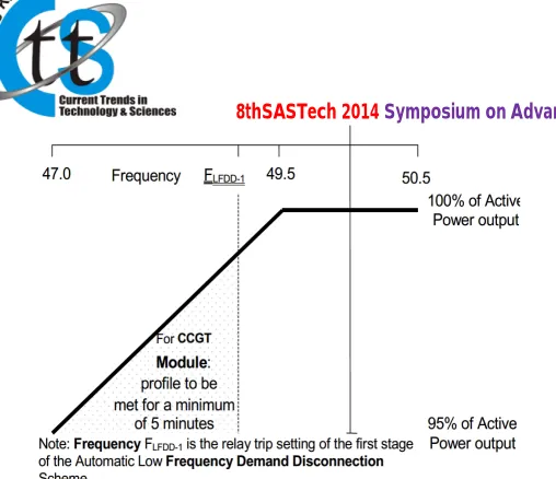
must be discontinued immediately if necessary. In the normal frequency power system, EPS is considered in stable condition. However, the angle changes in voltage transmission and distribution lines occur as a result of a sudden load change in supplying feeders. In this situation, if the voltage which is measured extremely fast cause the rise and fall of unauthorized operating frequency range, quick disconnect of the control unit will be occur in accordance with protected functions. Also, according to UK Grid Code, limitation of the frequency changes in normal conditions is presented and published between 49.5 and 50.5 Hz. In such circumstances, the frequency must be referred to 50 Hz by applying the control system. Figure1 specifies the frequency allowable changing rate in comparison with the change in unit power or attached area to the British power system. In this photo deployment time by gas units (CCGT) as a shaded position is allowed in less than 5 minutes. In figure 1, the frequency of FLFDD-1 is designed as the first
phase of the power plant relay setting or line breaker connected to the power system based on the British program. Some of distributed generation units have DC converters, according to the standards for transmission power system in England, DC converter which is installed in the output unit must be able to maintain their active input and adjust the frequency rate range from 47 to 49.5 Hz, so that if the under frequency is 47.8 Hz, active power input is not reduced more than 60% of the nominal level. Figure 2 demonstrates the mentioned conditions. It should be noted, in an island situation, production unit and DC converter are required to provide the load connected to the generator bus frequency range from 47 to 52 Hz. For gas units, the governor and controller as the frequency tuning devise are responsible for controlling the changes more than 0.05 Hz.
Table (4) Frequency changing limit for the connection to the UK (from 47 to 52 Hz)
Conditions Activity
Frequency range
Normal Conditions of continuous
47.5 to 52 Hz
Specific Activities in the period under 20s
47to 47.5 Hz
Unstable Unit or the connected equipment
must be removed immediately Less than 47 and
Copyright © 2014 CTTS.IN, All right reserved Fig. 1. The rate of the frequency allowable performance
range rather than change of power unit or area connected to the UK power system
Fig. 2. The rate of frequency allowable performance range performance rather than change of the power unit for DC converters in distributed generation sources
4.
V
OLTAGER
EGULATIONIn England and Wales step changes (sudden) of voltage level that occur during an error, up to the rate of 1% of the nominal voltage and high voltage level, shift of step changes up to 3% rate does not create a risk for the country's power transmission system. Also, for voltages above 132kV, flicker severity (short term) of 0.8 unit and a flicker severity (long term) of 0.6 unit, for voltages 132kV and below, flicker severity (short term) of 1.0 unit and a flicker severity (long term) of 0.8 unit is permitted.
5.
R
ANGE OFA
CTIVE ANDR
EACTIVEP
OWERAccording to Figure 3 the active and reactive power range is defined in the UK is defined power system. It is notable that the UK power system connectivity requirements (found in reference [12]), which are published in the UK Grid Codes is as the statutory provisions cited by all global power systems (50 Hz). According to the area which is limited to B and C shown in Figure 3, the rate of reactive power must not exceed from 5% of active power. Also, for England and Wales, in the area between A and B power factor is in 95% range.
Fig. 3. Allowable range of active and reactive power changes in the UK Grid Code
In Figure 3, each boundary condition is defined as follows:
Point A is equivalent (in MVAr) to: 0.95 leading Power Factor at Rated MW output
Point B is equivalent (in MVAr) to: 0.95 lagging Power Factor at Rated MW output
Point C is equivalent (in MVAr) to: -5% of Rated MW output
Point D is equivalent (in MVAr) to: +5% of Rated MW output
Point E is equivalent (in MVAr) to: -12% of Rated MW output
6.
F
REQUENCYC
ONTROLFrequency range of a power system is detected and controlled based on its grid codes and standards. In industrialized countries, the flexibility to frequency change of the allowable range is high. Usually a gap between the highest and lowest boundaries exists, but in developing countries, the frequency range of choices is more limited [7].
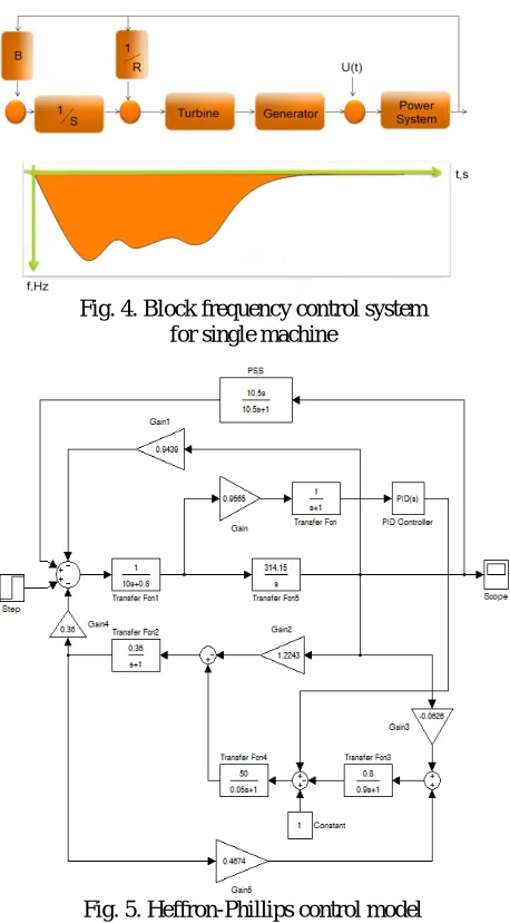
Disturbance in the power grid causes a mechanical oscillation in the generator shaft. This oscillation is sometimes referred to as rotary power. For stability of the power system, the risk of oscillations in the power grid must be avoided. Usually, in order to control the under frequency added to EPS due to sudden load or islanding of the generator the drawing control block in Figure 4 is used in Figure 4. In this control circuit first the frequency drop is decreased by the first loop and then by the secondary loop, the generator frequency is returned to the nominal amount [1] .But to control the frequency at the same time (ALFC) and voltage (AVR) the control circuit in Figure 5 which is called graphical Heffron-Phillips models is used [2]. The importance of frequency controller in power systems with wind farms is much higher than other power systems. Figure 6 and Table 5 show an overview of the range of bass frequency transients and the nearby bus terminal PCC9 (Binaloud
Copyright © 2014 CTTS.IN, All right reserved notable that in Khorasan power system and all power
systems with wind farms by applying error in different parts of the power system, rather scale oscillations can be seen in the output of the wind farm generators. And this requires the need for frequency control in these power systems.
Fig. 4. Block frequency control system for single machine
Fig. 5. Heffron-Phillips control model for single machine system
Fig. 6. Frequency changes of symmetrical three phase short circuit at the PCC
Table (5) Frequency ranges
Place of frequency measurement The highest
frequency rate The lowest
frequency rate
132 kV bus 50.463
49.709
PCC 50.463
49.785
WRIG Output 50.846
48.694
7.
B
INALOUDW
INDP
OWERP
LANTCopyright © 2014 CTTS.IN, All right reserved
Fig. 7. Connection of Binaloud wind power plants to 20 kV bus and relevant feeders
Fig. 8. Demand feeders connected to Binaloud wind farm's 20 kV bus dated on the 24th May 2013
8.
G
ASU
NITC
ONNECTION TOB
INALOUDW
INDF
ARMBased on standards connection of distributed generation generators to Iran's power system (developed by the Department of Energy), the acceptable operating range for frequency generators is from 49.5 to 50.5 Hz. In case of violation, protective equipment should automatically carry out a sequence of steps to cut in accordance with Table 4. This means that when the power system frequency is within the limits set in Table 4, distributed generation generator should be less than the values shown in the table for the frequency range of the power system to be disconnected. For distributed generation in distribution systems with a total capacity of less than 30 kW in common junction frequency adjustable spot and the cut time can be fixed or changed on site. For total capacity of larger than 30 kW, adjusted frequency at the site (according to local conditions and common junction) can be flexible. Adjustable values for frequency quantic protection must be coordinated and agreed to the local power system operation. For distributed generation generators in the spot power system that have make before break automatic transfer scheme for load transfer between the distributed generation and the power system,
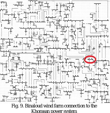
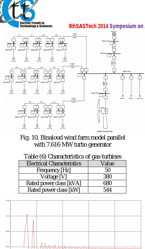
all requirements listed in this section must be complied regardless of the length of the parallelism of the two systems. The critical cut time is the time that takes from the first Frequency range violation to disconnect electrical equipment from PCC and includes the detection time and the delay which is due to timing relays [9]. Based on the Thevenin equivalent circuit of Khorasan power system (Figure 9), power system graph in Figure 10 is simulated for connection of synchronous generators to Binaloud wind farm in parallel form. Based on Figure 10, Connecting 7.616 MW gas-turbines (14 units of 544 kW generator) with synchronous machine type ECO40-2L/4 and with the basic information contained in Table 6, frequency oscillation output of PCC bus is plotted in Figure 11 by symmetrical three phase short circuit and continuing for 100 ms.
Copyright © 2014 CTTS.IN, All right reserved Fig. 10. Binaloud wind farm model parallel
with 7.616 MW turbo generator
Table (6) Characteristics of gas-turbines Value Electrical Characteristics
50 Frequency [Hz]
380 Voltage [V]
680 Rated power class [kVA]
544 Rated power class [kW]
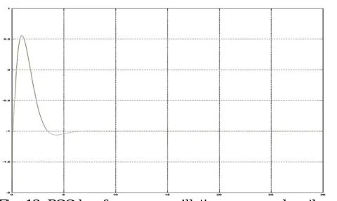
Fig.11. PCC bus frequency oscillations measured on the three phase symmetrical short circuit during 100 ms
Fig. 12. PCC bus frequency oscillations measured on the three phase symmetrical short circuit during 100 ms
Accordingly, obtaining information from the Khorasan power system in Binaloud bus viewpoint and connecting
Wind turbine energy conversion process is in this way that if the wind speed comes to allowing rate in the farm, it will be allowed to transmit power to the turbine blades (made from fiberglass and wood). The rotational energy of a gearbox (speed shifters) will be proportional to the nominal speed of the generator. This energy, generated by using a generator which is typically induction, is converted to electrical energy. Collecting of all turbine energy is injected to the power system at a point known as PCC. Wind power in addition to a sinusoidal oscillation which is the result of changing wind speed during day and night operation (or weekly or quarterly), the low-amplitude oscillations occur due to the dynamic vibration of blades, aerodynamic wind rotation, in contact with the blade and the inherent variability of wind. Although the gearbox acts as a mechanical damper filter in power transmission of turbine blades, some of these oscillations with higher time constants are observed in frequency and output power of the generator [7]. Remarkably, most wind turbines are connected to generators by gearbox. But the oscillation of wind power is the main problem of no gearbox turbines. However, because of the lack of agreement in volatility of wind power in turbines of a wind farm, a wide range of distortionary harmonics can be observed at the PCC. In addition to this and according to what was mentioned in the previous sections, generators of wind farms have a high sensitivity to power system frequency volatility and installed controllers in the power system must be tuned to small transition frequency oscillations and do not cause damaging dynamic oscillations on the farm blades. Applying a controller based on Heffron-Phillips model (Figure 5), for each synchronous generator and PSS set according to the classical control, the oscillation frequency can be adjusted. It is worth mentioning the type, technical issues, and system condition of gas-turbine supplies connection to the power system is not included in the standards. Controllers are usually specified in terms of conditions of each project. So in this article with the arrangement shown in Figure 10, and controller simulated (in MATLAB) in Figure 5, the circuit is modeled. In this model, the transfer function of the PSS is as in Equation 1:
GPSS = s Tw / (1+ s Tw) (1)
Applying a symmetrical three phase short circuit on the PCC bus during 100 ms, oscillations in the frequency
10
Copyright © 2014 CTTS.IN, All right reserved domain, as shown in Figure 11 DIgSILENT, is measured
3 Hz. Time allowed to the extent of continuity errors 100 ms is considered according to developing international standards of IEEE1547-2003 (In the 60 Hz power system of USA) and E.ON (50 Hz power system of Germany) wind resources. But because the protections that are currently installed on the Binaloud wind farm is not required to follow these standards, we consider frequency oscillation 6 Hz to regulate the controller in the worst situation (Fig. 12). In these circumstances, determining Tw = 10.5 sec, based on a simple block of Figure 5, and
the use of classical control criteria in linear systems, oscillations in the frequency range decreased to 0.5 Hz, the lowest TS11 reduced to from 25 seconds to 5 second (Figure 14). Load angle (or rotor angle in synchronous generators) fluctuated range is reduced in accordance with the controls.
Fig. 13. PCC bus frequency oscillations measured on the three phase symmetrical short circuit during 100 ms, then apply a controller in Heffron-Philips model and PSS Coordination in MATLAB
10.
C
ONCLUSIONWith the increasing development of human societies and promoting the welfare indicators, operation of DG increases its popularity from day to day. On the other hand providing constant and consistent power with the characteristics of power quality, power generation companies are competing criteria. In this paper, applying rules and regulations in the field of frequency, parallel gas unit connection with the Binaloud wind farm is studied to meet the demand of 20 kV feeders connected to the Binaloud bus. Discussing the importance of the frequency and impact on dynamics oscillations of wind turbine in the simulation and applying the controller of Heffron-Philips model in synchronous generator connection to a power system (SMIB) in the presence of the Binaloud wind farm and PSS set, the oscillation frequency was limited to 0.5 Hz in three phase short circuit condition on the PCC bus.
11
Settling Time
A
PPENDIX(A)
Table (7) Connection system response (critical cut time) to abnormal voltage conditions
critical cut time(sec) Voltage range (in percentage of
the nominal voltage)
0.16 V < 50
2 50 ≤ V < 88
1 110 ≤ V < 120
0.16
V ≥ 120
R
EFERENCES[1] M. Ansari, M. Eidiani, “Investigate How to Reduce the Volatility of PSS 400 kV Power Line Communications Power Systems in Khorasan and Across the National Power System", National Conference Power Plants, Iran, Ahvaz 15th and 16th February 2013.
[2] B. S. Surjan, R. Garg, "Power System Stabilizer Controller Design for SMIB Stability Study", International Journal of Engineering and Advanced Technology (IJEAT) ISSN: 2249 – 8958, Volume-2, Issue-1, October 2012.
[3] P. Kundur, "Power system stability and control", New York: Tata McGraw-Hill, 1994.
[4] P.M Anderson and A. A. Fouad, "Power System Control and Stability", Volume- I, Iowa State University Press, Ames, Iowa 1977.
[5] F. P. Demello, C. Concordia, "Concepts of Synchronous Machine Stability as Affected by Excitation Control", IEEE Trans. On Power system and apparatus, Vol-PAS-88, No.4, April 1969. [6] Heffron, W.G., Phillips, R.A, "Effects of modern
amplifying voltage regulator on under-excited operation of large turbine generators", AIEE Trans., 1952.
[7] M. Ansari, "Developing Grid Codes of Voltage, Frequency, Active and Reactive Power of DG Connection to the Khorasan Power System, M.Sc. Thesis, Islamic Azad University, Bojnourd, 2013. [8] IEEE Ste. 1547 2003, Standard for Interconnecting
Distributed Resources with Electric Power Systems.
[9] "Connection of dispersed generation to generation power systems" standard, Islamic Republic of Iran, Ministry of Energy, Department of Power and Energy, October, 2013.
[10] M. Ansari, N. Sargolzaei, "Design and development of mining properties and to comply with the Grid Code FRT Binaloud wind farm E.ON to review the regulation of protective relays", International Power System Conference (PSC), Tehran, 13-F-REN-1220, November, 2013. [11] Michael J. Basler and Richard C. Schaefer, "Understanding Power System Stability", IEEE Trans. On Industry Application, Vol. 44, No. 2, March/ April, 2008.
Copyright © 2014 CTTS.IN, All right reserved engineering. His research includes power
system development with Renewable Energies. His main research interests include: Extract Khorasan regional Voltage, Frequency, Active and Reactive connection Grid codes with presence of Distributed Generation.
![Table (1) Range of frequency change according IEEE-1547 Std. [8]](https://thumb-us.123doks.com/thumbv2/123dok_us/8796484.1769498/2.595.58.289.327.404/table-range-frequency-change-according-ieee-std.webp)