ISSN :2394-2231 http://www.ijctjournal.org Page 100
Automatic Smart Solar Radiation Tracker
Samudrala Vinay Kumar
1, KSK Mohammad Ayub
2, Mrs. T. Theresal
31,2
VIII Semester ,ECE Department ,3Assistant Professor, ECE Department SRM University, Chennai
---
************************
---Abstract:
The best approach to get the maximizing output efficiency of solar system is sun tracking. The proposal in this paper is a system that used to control the movement of solar panel so that it constantly faced towards the sun direction[1]. Solar modules is a devices that used to convert light energy into electricity and gives a practical solution for the problem of power generation.
The solar tracker that designed and constructed in this project gives a best method of aligning a solar module with the sun in order to get maximum output. Automatic smart solar radiation Tracking System is best hardware module, which automatically turns the solar panel along with sun and provide best alignment with the sun to get maximum output in the form of electricity.
---
************************
---I. Introduction
As technology is increasing day by day everything is depended on electricity. So the demand for electricity is more in the world market. To get best electricity which is eco-friendly is renewable energy, among some renewable energy solar energy is one and it is one of the rapidly growing projects in current world. Whenever we are going out from home the sun is shining on us and it is sending some energy towards our direction. Generally we can feel the heat that coming from the sun, and we can also able to see some objects are moving across the sky that are illuminated from the sun. Similarly, if we could place a solar panel to rotate along with the sun for all the day then the solar panel could receive maximum amount of sunlight and that energy is used to convert into electricity.
Everyone knows that sun rises in the east and moves around the sky and sun set occur at the west direction. To this if we could place a solar panel that moves continually with the sun across the sky from east to west, it could get more energy when compared to the fixed solar panel. One way to rotate the solar panel is of course by hand to rotate all the solar panels through the day is a big issue it uses the person’s time. Going outside to a solar
panel for every hour to turn it toward the sun might be possible, but this process is not efficient method[2]. Some LDR’s are employed to control the solar panel tracking system. For example, if the LDR is not aligned along the axis of sun, then it could turn on the gear motor until it is once again aligned. If the motor is attached to the frame holding the solar cell, then the solar cell could be moved to face the sun. As long as the photo sensor is in alignment with the sun, nothing happens[1]. However, when the sun moves across the sky and is not in proper alignment with the LDR, then a motor moves the frame until the photo sensor is in the sun once more[2].
.Block Diagram :
Figure 1
ISSN :2394-2231 http://www.ijctjournal.org Page 101
II CONSTRUCTION
The main objective of the project is to get more efficient output when compared to the fixed solar panel. The Construction has mainly hardware parts.
The main components in hardware part are .Ldr’s, Arduino controller,L293D IC, Gear Motors, Solar Panel. This LDR’s acts as input signals to the Arduino controller and according to that signals the motor start working[3].
1.LDR’S:-
LDR is a light dependent resister. In our project LDR act as input signal. We know that it exhibits photoconductivity It receives various light signals from the sun and converts into digital form with the help of Arduino[1].
Figure 2
2.Arduino Controller:-
With the help of Arduino the input Analog signals are converted into digital form. It has fourteen digital input output pins. Six pins are used as power outputs and six pins are used as analog inputs, USB connection and reset button[1]. we should write a program in Arduino software and should be placed connection with the laptop and USB port of Arduino and the program what we given should be verified & uploaded.
Figure 3
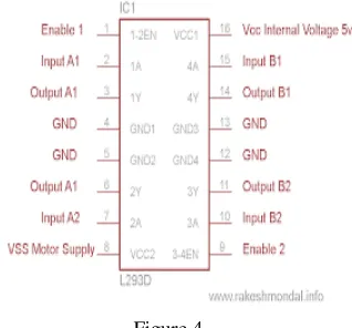
3.L293D IC:-
L293D is a sixteen pin IC. In this IC it consist of two Bridge circuits. With the help of this H-Bridge circuits the gear motor are able to move in any direction. With the pins 2 and 7 & 10 and 15 the operation of two motors are controlled. If pin 2 is given as zero and 7 is given as one then it will rotate in clock wise direction. If we give the logics reversely then the motor will rotate in counter clock wise direction and same for the pins 10 and 15[4].
Figure 4
4.Gear motors:-
Hear we are using 30 RPM ,12 volt ,300ma gear motor. This gear motor gives required torque to rotate the solar panel. Why we are using this gear motor because it is very easy to decrease the speed of the motor when ever it rotates fast[1,3].
Figure 5
5. Solar Panel:-
ISSN :2394-2231 http://www.ijctjournal.org Page 102 and wide use in power generationar. We are using
WS3A model solar panel it gives 12 volt output[3].
Figure 6
III Methodology
Figure 6
To program the user interface between the Host Pc and the transmitter Arduino. To program the transmitter Arduino to send signals towards gear motors to drive them in respective directions to connect LDR’S to the Arduino which is used to sense the light intensity[6,4].
Each LDR is placed at certain angles (a).A0 at 45 degree
(b).A1 at 90 degree
(c).A2 at -45 degree
(d).A3 at 45 degree other axis
(e).A4 at -45 degree other axis
When light falls on A0 the monitor shows that the intensity of light is more on A0 indicating the Gear motor to rotate 45 degrees with respect to A1
similarly for A2.when light intensity is more on A1 the gear motor 1 should rotate from A0 – A1.Similarly for A0-A2.When light Intensity is more on A3 the motor m1 should rotate back to A0 and the motor m2 should rotate to A3.Similarly for A0-A4.In this way the solar panel can cover up to five different directions[4,6].
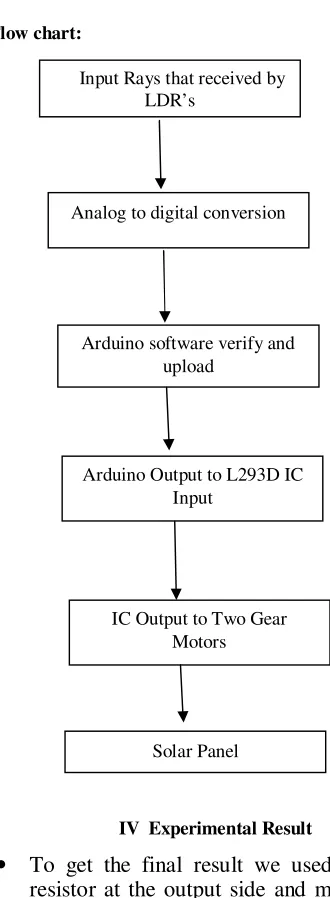
Flow chart:
IV Experimental Result
• To get the final result we used 470 ohms resistor at the output side and measured the voltage across it and current flowing through it with the help of a multi meter.
• As we got voltage and current power is calculated with the help of a formula P=I*V
Input Rays that received by LDR’s
IC Output to Two Gear Motors Analog to digital conversion
Arduino software verify and upload
Arduino Output to L293D IC Input
ISSN :2394-2231 http://www.ijctjournal.org Page 103 • According to the ohm’s law equation we
know that V=I*R if we substitute this
formula in power then it will become P=I^2*R.
P= power ,I=current ,V=voltage ,R=resistance
Test as been done for one day from 28-03-2017 to 29-03-28-03-2017 at an angle of 90 degrees where the solar panel is in fixed position it means no tracking part will be done by the solar panel and another testing is done with tracking solar panel and we have noted values.
Table 1:
Current vs Day time for rotating and fixed solar panel[3]
Voltage vs Day time for rotating and fixed solar
Panel[3].
Power vs Day time for rotating and fixed solar panel[3]
This is the final output that we got after calculations. Hence we have shown that rotating solar panel gained more energy when compared to the fixed solar panel.
V CONCLUSION
LDR based solar panel has been implemented and discussed. This is a multi–axis automatic smart solar radiation tracker. The main advantage of this
Time
Rotating Solar Panel
Fixed Solar panel
Voltage
V
Current
mA
Power
W
Voltage
V
Current
mA
Power
W
6:00 9 241.6 2.174 8.5 144.6 1.229
7:00 9.6 269.8 2.590 9.3 174.6 1.623
8:00 9.66 298.4 2.882 9.6 224.3 2.153
9:00 9.69 302.3 2.929 9.6 297 2.851
10:00 10.01 366.3 3.666 9.91 344.5 3.413
11:00 10.07 363.5 3.660 10.07 362.9 3.654
12:00 10.06 362.6 3.647 10.03 346.8 3.478
13:00 9.98 298.1 2.975 9.78 288.3 2.819
14:00 9.7 274.6 2.663 9.5 223.8 2.126
15:00 9.66 264.1 2.551 9.4 175 1.645
16:00 9 234.5 2.110 8.8 134.5 1.183
17:00 8.7 198.1 1.723 8.2 124.9 1.024
Rotating Panel (in W-hr)
Fixed Panel (in W-hr)
33.576
ISSN :2394-2231 http://www.ijctjournal.org Page 104 system is its low cost of manufacturing. Maximum
directions of tracking is covered with the help of five LDR’s. The power that we gained is 20 to 26% greater than the fixed solar panel. The amount of power that gained is stored in the battery.
VI REFERNCES
1. Somnath Meikap , Subrata Dey
“Development of a Low Cost Optimum
Power Tracking Prototype for Solar
Energy”.IEEE 2016
2. Md. Sohag, Md. Hasan, Mst. Khatun, M. Ahmed, “An accurate and efficient solar tracking system using image processing and LDR sensor”, IEEE Trans., page 522-525, EICT 2015
3. A. Stjepanovic, S.Stjepanovic, F.Softic, Z. Bundalo, “ Microcontroller based solar tracking system”, TELSIKS 2009, IEEE Trans., page 518-522.
4. Eduardo Lorenzo (1994). Solar Electricity: Engineering of Photovoltaic Systems. Progensa. ISBN 8486505550
5. Jenny Nelson(2003). The Physics of Solar Cells, Imperial College Press, ISBN: 978-1-86094-340-9
6. S. Wang, W.Gao, and S.Huang, “Research
on the mixed two-axes suntracker,”
Renewable Energy Resources, vol.25, no.6, pp.10-13,2007
7. Applications, "IN: general formula for
on-axis sun- tracking system,Kok-Keong
Chong, Chee-Woon Wong , InTech Europe, pp.263-292October, 2010.
8. Renewable Energy : An overview,