ISSN 2319-7625 (Online) (An International Research Journal), www.chemistry-journal.org
Is Zero Liquid Discharge a Feasible Solution?
Payal B. Joshi
Mukesh Patel School of Technology Management & Engineering, SVKM’s NMIMS (Deemed-to-be-University),
Bhaktivedanta Swami Marg, Opp. Cooper Hospital, Vile Parle, Mumbai-400056, Maharashtra, INDIA.
email: [email protected].
(Received on: November 7, 2016)
ABSTRACT
Strict environmental regulatory norms, water scarcity and growing awareness of environmental issues are the major drivers for adoption of zero liquid discharge (ZLD) technology in industries. This article presents a review on concept of zero liquid discharge, processes involved, examples of ZLD treatment plants in textile, pharmaceutical, and metal finishing industries, challenges, opportunities and feasibility in application-specific industrial setting.
Keywords: zero liquid discharge, waste water.
INTRODUCTION
NEED FOR ZERO LIQUID DISCHARGE
Water is required in several industrial processes such as steam generation, crystallization, scrubbing, extraction, etc. After the use of water in multiple processes it leads to formation of waste water streams that is disposed after suitable treatment. This is called as the ‘end-of-the-pipe’ non distributed waste water clean-up 1. It is already a known fact that
water is a limited resource, therefore adopting methods to reuse water is a plausible solution. However, water reuse in industries will require complete cleaning treatment techniques. Water reuse, stricter environmental regulations on industrial effluent release and Clean Water Act (1974, revised 1977, 1982) are the major factors for ‘zero discharge’ or ‘zero-liquid discharge’2. It is suggested that these regulations should be strengthened as new EPA
guidelines are expected in 2017 and 2022 with special emphasis on zero-discharge3.
In 1997, Formosa Plastics Corporation signed an agreement with Wilson, the Environmental Protection Agency (EPA), Texas Natural Resource Conservation Commission (now Texas Commission on Environmental Quality) and attorney Jim Blackburn to reduce its discharge of wastewater to zero. As a result of Wilson-Formosa Agreement, a comprehensive analysis towards reaching zero discharge system was commenced. According to the agreement, the list of candidate solutions were developed that is economically beneficial, environmentally superior and technically proven to be effective in a similar industrial application5.
According to second law of thermodynamics, there is no ‘zero discharge’ possible, as it clearly states that conversion of thermal energy to useful work necessitates a certain amount of energy must be released6. Thus, complete recycling is a complex chemical factor that seems
virtually impossible. Industries and small-sector enterprises have adopted zero-to-near zero discharge techniques. The industries where ZLD can be adopted are power plants, fuels, metal processing, pulp-paper, petrochemicals, oil refining, fertilizer, textiles, pharmaceuticals, tannery and ethanol production.
TECHNIQUES TO ACHIEVE ZERO DISCHARGE
In general, industrial effluents contain high concentrations of salts, suspended total dissolved solids (TDS), chemical oxygen demand (COD), toxic compounds like heavy metals, dyes, surfactants, chlorinated solvents, etc. The goal of zero discharge is to recycle all treated waste water back into the manufacturing process. In India, as per CPCB notification (2015), guidelines for zero discharge for water-polluting industries were drafted7.
Most industries use water in different processes based on the applications. Hence, the waste streams generated is widely varying in composition. One of the main problems when designing a ZLD system is determining the type of waste stream generated. Composition of effluent water, flow rate and purity demand of water are some factors that are essential while designing a ZLD system. As the concentration of effluent is varying, it is challenging to design a generic ZLD system. In simplest terms, a typical ZLD system comprises of:
a. Pre-treatment (Physico-Chemical and Biological) b. Reverse Osmosis (Membrane Processes)
c. Evaporator and Crystallizer (Thermal Processes)
wastewater. Trickling filters and activated sludge methods are commonly adopted biological treatments methods in most industrial plants. Membrane technology is considered as the tertiary waste water treatment process used for removal of trace suspended solids from effluents of chemical treatment processes. This is also a membrane separation method that is used to remove several types of large molecules and ions from solutions through application of pressure to the wastewater on one side of a selective membrane. The result is that the contaminant is retained on the pressurized side of the membrane and the treated waste water is allowed to pass to the other side. Use of activated carbon, UV rays, ion-exchange methods are also employed for the purpose. The above processes are advanced waste water treatment technologies utilized in tandem to achieve ‘near-zero’ to ‘zero discharge.’8
Designing and installing different discharge technologies is labor intensive and expensive. Hence, European Union Member States are required to implement the IPPC Directive in national law and ensure the existence of rigorous approval requirements on the basis of best available techniques (BAT). The Integrated Pollution Prevention and Control (IPPC) Directive 2008/01/EC of the European Union form the basis within the European Union of the permit procedure for industrial installations. The IPPC Directive is based on the concept of Best Available Techniques (BAT)9. Some case studies have been presented
including textile, pharmaceuticals and metal finishing.
Textile Industry:
It is considered as the major water intensive sector producing effluents with high levels of TSS, dissolved fibres, enzymes, starch, BOD, bleaching agents, surfactants, salts, resins, waxes, urea, alkalies, hydrocarbons and dyes10. European companies increasingly import
textile products from outside the EU, especially from developing countries like India and China. These products are finished in the EU, or sold directly. Hence, there is an urgent need to streamline zero-discharge technologies to be comparable with industries in the EU.
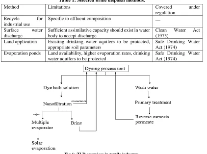
The illustrative example is of Tirupur textile plant in Tamil Nadu, India, where ZLD technology is adopted. In view of the deteriorating water quality in Noyyal river making it unfit for irrigation, Madras High court made it mandatory for the polluting industries to have zero liquid discharge (ZLD) system. Ninety units were closed for not providing zero liquid discharge system. Based on the directions of the Madras High Court and TNPCB in 2005 the bleaching and dyeing units in Tirupur implemented CETPs and IETPs to meet the Zero Liquid Discharge (ZLD) norms.
Based on Fig.1, technology involves common effluent treatment plant (CETP) reverse osmosis and mechanical vapor recompression for the final reject of effluent.
Table 1: Selected brine disposal methods.
Method Limitations Covered under
regulation Recycle for
industrial use
Specific to effluent composition __
Surface water discharge
Sufficient assimilative capacity should exist in water body to accept discharge
Clean Water Act (1975)
Land application Existing drinking water aquifers to be protected, appropriate soil parameters
Safe Drinking Water Act (1974)
Evaporation ponds Land availability, higher evaporation rates, drinking water aquifers to be protected
Safe Drinking Water Act (1974)
Fig.1: ZLD overview in textile industry.
High scaling (due to hardness) and corrosion (from chlorides) results in poor performance of the equipment. Crystallization of mixed salts in industrial effluent is complex and energy-intensive method. High operating costs as a typical crystallization costs after MVR is in the range of 600 to 650 (INR) per m3 of feed. However, possible improvements involve
use of multi-effect evaporator for RO water permeate followed by crystallization of salts and their reuse. The other side of the case was recently reported where the plant is struggling to exist with stringent guidelines11.
Pharmaceutical industry: In general, pharmaceutical waste comprises of organic compounds, high COD, toxic solvents like methanol, isopropyl alcohol, ethanol, and minimal suspended solids. As suspended solids are in trace amounts, the first step of treatment is chemical precipitation followed by biological processes. Organic compounds present in waste sludge are of varying nature ranging from emulsions, colloids to binding/chelating agents.
respiratory and inflammation. AstraZeneca effluent plant at Avlon Works, Avonmouth, UK has been designed to meet the current and likely future expansion of effluent load from the plant along on site effluent treatment. The advanced control system incorporated at the site allows remote administration of the SCADA (supervisory control and data acquisition) system, allowing retaining of historical data to back check the efficiency of waste water plant.
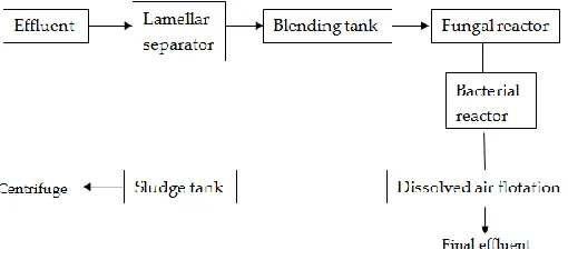
The plant divides effluent streams as per COD levels. Effluent is sent in a lamellar separator followed by blending tank to eliminate carbon particulates (Fig.2). Next, the effluent is sent in a fungal bioreactor maintained at pH=4.0 which is then raised to pH = 7.0 to allow bacteria to proliferate. Effluent streams are treated in a moving bed bioreactor (aeration and agitation) followed by phosphate removal and dissolved air flotation plant where final sludge is separated and sent for safe disposal making it a ‘near-zero’ plant12. Biomass flocculation is
done by adding ferric sulphate in minimum dose. Fungal bioreactor removes 60% of the COD load while the bacterial reactor can eliminate 80% of COD load.
Fig. 2: Typical zero discharge in a pharmaceutical industry.
Metal finishing Process: Metal finishing industry is one of the largest industrial activities that involve wide range of chemicals, especially heavy metals. If the effluent is not properly managed, it can adversely affect public health and environment. One of the metal finishing processes is electroplating that involves deposition of a thin protective layer (metallic) on a base metal, using electrochemical processes. This process imparts corrosion protection, surface hardness, aesthetical attributes like colour and lustre (Fig.3.)
In a typical electroplating process, base metal is made cathode and the coating metal is made anode dipped in an electrolytic bath. The process involving cleaning and pre-treatment stages use toxic solvents like chlorinated hydrocarbons and surface tripping like caustic soda and strong acids like hydrochloric and sulphuric acids, depending on the metal surface to be plated. Fig 3, depicts general electroplating process line and composition of effluent streams from various steps. Generally, waste water from metal finishing units comprise of heavy metals such as cyanide, hexavalent chromium, total chrome content, acid waste, metal salts, oils-grease emulsions, and other dissolved solids13.
As depicted in Fig 4, oily waste water stream is mixed with alum, followed by demulsification and oil is skimmed by gravity settling. Cyanide oxidation involves destroying cyanide via reacting with sodium hypochlorite in NaOH conditions. Hexavalent chromium reduction to trivalent form (Cr6+ Cr3+) is done in batch process using sodium bisulfite in
acidic conditions or continuous process using sulphur dioxide in HCl conditions.
Fig. 4: Typical metal finishing wastewater treatment flow diagram.
After reduction, trivalent chromium is precipitated as a hydroxide and separated. Chemical precipitation of dissolved and complexed metals is achieved by reaction with hydrated lime and removal of precipitates by gravity settling in a clarifier. pH for metal precipitation is maintained in the range of 8.5-11 depending on the mixture of metals present. Sludge obtained from various stream treatment is later dried using gravity drainage and evaporation processes. Precious metals are recovered from solvents and reused as catalysts, electrode making, etc. Rinse water is also recycled and reused.
As per COINDS (2007), there are above 600 automatic electroplating plants in the country14. Electroplating operations can be found as individual plating units or form part of
Electroplating units operating in Ludhiana, India is one of the best examples of zero-to-near zero discharge plants. With over 500 electroplating units operating in Ludhiana, there is generation of toxic effluents containing heavy metals like nickel, zinc, chrome, copper, iron etc. CETP for these electroplating units is working on zero liquid discharge technology and no effluent is practically discharged. The treated effluent from electroplating units is reused by dyeing industries. Treatment process used by CETP comprises of physico-chemical treatment as a primary treatment, followed by biological treatment. After this, activated sand filters are used followed by ion exchange, reverse osmosis, and finally multi effect evaporator techniques to obtain final treated effluent, which is reused, thus making this CETP a ZLD setup with TSS discharged in negligible concentrations.
CONCLUSIONS
Several industrial plants have achieved near zero liquid discharge (n-ZLD) such as textile, pulp-paper, metal-finishing, distilleries, tanneries, power plants, etc. Near-zero liquid discharge seems a plausible solution in major industries, but face challenges. Due to high capital costs, energy intensive steps, near-zero-to-zero discharge technology is still at a primitive stage in India. The major shortcoming of ZLD is that no single technique can be employed for effluent treatment as each effluent stream composition is different, hence common effluent treatment plants (CETPs) are facing serious challenges. Though, thermodynamically, it is improbable to attain zero discharges, utilizing mathematical programming, except some industries, zero liquid discharge can be employed15. The global
estimates reveal that total market potential of ZLD may reach 210 billion by 202016. Water
was always considered an underpriced resource, but with the implementation of zero-to-near zero discharges, there is a shift in focus where polluters need to devise methods to achieve least environmental impact (EI).
REFERENCES
1. Belhatche D.H. Choose appropriate waste water treatment technologies, Chemical
Engineering Progress, 91(8), p.32-51 (1995).
2. Clean Water Act, https://www.epa.gov/laws-regulations/summary-clean-water-act (2016). 3.
https://www.epa.gov/smm/epa-sustainable-materials-management-program-strategic-plan-fiscal-years-2017-2022 (2016).
4. Ford D. Zero-Discharge & Environmental regulations, the Toxic release Inventory & Natural laws, Environmental Engineer, 32(4), p.10-23 (1996).
5. Blackburn J, Ford D, Wilson-Formosa Agreement-Summary (1998). 6. Mortimer. R.G, Physical Chemistry, Academic Press, 3rd ed, p. 106 (2000).
7. Guidelines on Techno-economic feasibility of implementation of zero liquid discharge for water polluting industries, CPCB (2015).
9. Promotion of Best Available Techniques (BAT) in the Textile and Leather Industry in Developing Countries and Emerging Market Economies (2003).
10. http://eippcb.jrc.ec.europa.eu/reference/ (2016).
11.
http://economictimes.indiatimes.com/industry/cons-products/garments-/-textiles/tirupurs-textile-industry-struggling-to-stay afloat/articleshow/50606811.cms (2016).
12. Environmental sustainability, report by AstraZenenca, Sustainability Update (2015). 13. Cleaner Production in Electroplating Industries, Information Bulletin, APPCB (2004). 14. Comprehensive Industry Document on Electroplating Industry (COINDS), CPCB (2007). 15. Anantha P.R, Bagajewicza.M.J, Dericks.B.J, Savelski. M. J. On zero water discharge
solutions in the process industry, Advances in Environmental Research, 8(2), p.151–171 (2003).