DEVELOPMENT OF A HEAT PIPE AND GREY BASED TAGUCHI
METHOD FOR MULTI-OUTPUT OPTIMIZATION TO IMPROVE
THERMAL PERFORMANCE USING HYBRID NANOFLUIDS
Mohammed Yunus
*Mohammad S. Alsoufi
Department of Mechanical Engineering, College of Engineering and Islamic Architecture, Umm Al-Qura University, Makkah, Kingdom of Saudi Arabia
A
BSTRACTSwift cooling systems, improved microprocessor chips, processors’ performance and power usage have increased production of an enormous amount of heat and high operating temperatures due to excess heat flux density in the field of microelectronics. A rapid cooling of electronic circuits and heat dissipation for the same size of pipe with the present technology as nano size circuits critically generate high heat flux beyond 100 W/cm2 is currently the challenging task with which we are presented. Cooling in the form of heat transfer should be managed using both thermal conductivity (evaporation) and phase transition (condensation) between the two solid interfaces due to the higher amount of heat fluxes, high heat carrying capacity in a smaller size of heat exchangers as well as the heat pipe. A comprehensive knowledge of this mechanism is yet to be achieved, despite the fact that a heat pipe operates against gravity and a high heat carrier capability. In this article, a detailed study of the performance of a heat pipe (temperature gain and heat transfer capability) under the influence of various working parameters such as working fluid, a wick structure, thermal properties, heat input and applications of the field is carried out in order to increase the cooling capability of the heat pipe. Also, the optimum level of various working parameters on the thermal performance of a heat pipe using a Taguchi-Grey analysis has been presented followed by ANOVA and confirmation tests.
Keywords: Heat Pipe, Thermal Resistance, Wick Structure, Grey Relational Grade, Taguchi Grey Method.
1.
INTRODUCTION
In the present scenario, due to rapid development and increased usage of microelectronics in computer industries, the computational heat pipe plays a more important role in energy efficiency (Ochterbeck, 2003). Some measures are taken to improve the cooling performance of heat transfer equipment such as heat spreaders, heat pipes, and vapor chambers. A heat transfer device consists of a metal tube sealed at either end. The wick structure is lined with capillary material and contains a small amount of working fluid in a partial vacuum, the liquid absorbs heat at one end by vaporization and condenses the vapor by releasing the heat at the other end. Heat pipes are one of the most efficient procedures to transport thermal energy from one point to another (Chi, 1976). In electronic cooling systems, a heat pipe is used as a passive device containing no mechanical moving parts and typically requires no maintenance. It transfers heat uses two principles of thermal conductivity and phase transition to regulate the transfer of heat efficiently (Launay et al., 2007).
General Motors Corporation (Gaugler, 1944) initially invented the concept of the heat pipe. Grover rediscovered unusual properties of the heat pipe independently and followed this with serious development work additionally. He signified as inside specific limitations the manner of utilization and viewed it as a synergistic designing structure which is identical to a material having thermal conductivity greatly surpassing that of any known metal. There have been considerable research attempts to increase the efficiency of the heat pipe by selecting different geometries or working fluids or operational modes (Ahmad et al., 2010). Working
* Corresponding author. Email: [email protected]
fluids play a significant role in the heat transport capability of heat pipes, and several nano-fluids are widely used to improve thermal performance. Heat pipes have more advantages regarding efficiency and conduction of heat over many other mechanisms of heat dissipation as well as in the transferring of heat in comparison to a solid-copper cross section meant for a considerable distance (Ma et al., 2006). In a small light-weight structure, a comparatively large amount of heat transfers in a heat pipe which is a second main feature of a heat pipe. Latent heat is the amount of heat transported by vaporization in different orders of magnitude and which is comparatively more efficiently transported than with a conventional convective of sensible heat with the same temperature difference. It is expressed as comparable thermal conductivity to the heat pipe for its performance. In applications where conventional cooling methods are not suitable, heat pipes are very frequently used. When a heat pipes need arises the selection of heat pipes should be an appropriate one which is not an easy task. For applications involving energy conservation, the heat pipe is a prime candidate, and the heat dissipation system is the main advantage of an energy conversion device (Korn, 2008). Due to increased fuel costs and decline in the reserves of fuel heat pipes which conserve energy become more important in a significant number of applications to use as a useful tool for conservation.
The conventional heat pipe is used as a heat transfer device which contains a wick like metal mesh inside and liquid as the heat transfer medium (Liu et al., 2011). The important property of a heat pipe is to transfer heat along its length by liquid vaporization at the low-temperature drop at the evaporator of the heat pipe or heat source. The vapor gets condensed in the condenser or heat sink, and then the liquid will move in the opposite direction inside the wick through capillary
Frontiers in Heat and Mass Transfer
force. Also, it is possible to use heat pipes alternately for cooling and heating processes by changing the heat flow direction in the heat pipe.
2.
Literature Review
In the mid-nineteenth and twentieth century, the Perkins family introduced a prototype of heat pipe known as the Perkins tube in the United Kingdom and drew up a series of patents. In the many Perkins tubes, heat pipes were wickless gravity-assisted devices (thermosyphons), by which the transfer of heat was attained by a change of phase (the latent heat of evaporation). Among the many heat transfer systems, the heat pipe is one of the most efficient systems today. The primary purpose of a heat pipe in other conventional processes is the transfer of heat in large quantities at a considerable distance in a small cross-sectional area without any external power supply to the device. Furthermore, the heat drops from one end to another end in a small quantity and it can transfer high heat rates at different levels of temperature and also the design and manufacturing are very simple, so these are the exceptional features of the heat pipe (Gaugler, 1944).
There were many prototype heat pipes, but in the first, water and subsequently sodium was used as the working fluid to operate at 1100k (E2109-01). The heat pipe used the idea of a time function and developed it in a considered way (Trefethen, 1962). The heat pipe shows a high-performance equivalent to a thermal conductivity significantly exceeding that of metal. The preliminary theoretical results and design tool of the heat pipe is reported as a reliable thermal device (Cotter, 1967). To convert the thermionic diode Harwell experimented on sodium heat pipes in the atomic energy laboratory of the UK, and similarly, scientists are starting research on heat pipes at the Joint Nuclear research center in Ispra. The heat pipe used in micro gravitational fields was without external force due to the capillary tube. This meant that this product was, for the most part, used in space applications and also there are some devices of a heat pipe which are mainly used in electronic devices such as laptops and computers to remove heat from processors.
Experiments conducted with single-phase movement have a lower result in terms of heat transfer compared to the two-phase system (E2109-01). Various heat exchangers for effective thermal control inside the heat transfer device of different heat pipes for energy saving and environmental protection by using thermal relations in various structures have been carried out (Vasiliev, 2005). Various simulations on the fundamentals of heat pipes under different operating conditions for a particular approach linked to full imitation below steady state are carried out. Wick and gas (vapor) are included in the heat pipe simulation such that both are passing under stable state working conditions (Faghri et al., 2010). Navid et al. (2012) reviewed heat pipes to improve heat transfer by using nano-particles and warming of Nanofluids in recent years for an optimum condition during steady state operation having extremely high thermal conductance. The circulation takes place in the heat pipes by different forces such as capillary, gravitational and other forces directly.
Kang et al. (2006) researched the thermal density of electronic parts to employ nanofluids (Aqueous solution of silver (Ag) nano particles of 10 nm diameter) as working fluid for the conventional heat pipe. Kamble et al. (2014) experimented with the behavior of hybrid nanofluid (Al2O3 + CuO) into the circular heat pipe to improve the thermal resistance under different operating conditions with the effects of charged volume ratio on working fluids. The thermal resistance decreases and increases to 2% volume concentration (VC) with the increase in VC of hybrid nanofluids and inclination of the pipe respectively, with the distilled water as a working fluid, heat input increases.
Septiadi et al. (2013) presented work on the heat pipe for the passive cooling system of the nuclear reactor using Nanofluids with a screen mesh wick having nano-size particles (Al2O3 + TiO2) and water as base fluids. The average diameter of 20 nm nanoparticles was made with 1% - 5% volume fraction. On the screen mesh of the wick structure, the thin sedimentation of Nano-fluid takes place to improve the capillary performance.
2.1. Heat Pipe Components
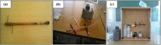
These consist of three components namely, container, working fluid and capillary (or wick structure), see Figure 1. The Container has various functions in which the working fluid should be isolated and be leak proof with the pressure difference maintained from the wall surrounding and thus allowing heat transfer from the working fluid. There are various factors involved in the selection of container materials such as compatibility, thermal conductivity, strength to weight ratio, porosity, ease of fabrication (machinability, ductility, and welding) and wettability. The most important of these is the high strength to weight ratio in an aircraft. A non-porous material is used to avoid vapor diffusion. For the small temperature drop between the wick and heat source, a high thermal conductivity is guaranteed. By considering all parameters, we have selected Copper for the container part as shown in the Figure 1(c) because it has the higher thermal conductivity of 358W/m-k.
Fig. 1 (a) developed conventional heat pipe, (b) experimental setup with overall heat pipe setup and (c) test-rig used
The selected working fluid was recognized and identified for the operating gas temperature range within the estimated temperature group considering that most of the characteristics had to control the substantial application. The main requirements of working fluids are compatibility with and wettability of wall materials and wick, good thermal strength, high latent heat, high thermal conductivity, low vapor, liquid viscosities and high surface tension. The different working fluids and their operating temperatures are as shown in (Lin et al., 2008).
Inside the heat pipe, the wick structure is present to rotate the evaporator and the condensate section. Small pores are required at the liquid gas interface to develop the high capillary pressure and large pores are chosen inside the wick structure for easy movement of water through the wick. Some of this was in order to improve the performance of heat pipe capillary and for the same reason they developed the different types of wick structure. The two different types of wick structure are the homogeneous and the composite. Homogeneous wicks are comparatively simple to install, and their manufacture and design offers most benefits. The composite wick has the drawback of high manufacturing costs, but it raises the capillary limit considerably. Understanding the drawbacks and benefits of all types of wick clearly helps in selecting the particular application of wick structure. The main advantage of the wick is to transfer the liquid between the evaporator and the condenser of a heat pipe. The wrapped screen wick is the most commonly used wick structure. In terms of heat pipe design, there are three important properties of the wick to be satisfied namely: minimum capillary radius, permeability and transport of heat capability (Yunus et al., 2016).
2.2. Heat Pipe Components
the highest GRG. Finally, confirmation tests will be carried out to verify the experimental results with an optimal set of values (Manimaran et al., 2012; Yunus et al., 2015, 2016, 2017).
3.
MATERIALS AND METHODS
3.1.
Experimental Procedure
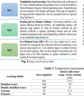
The heat pipe used to have a dimension of 10 × 300 × 1 mm carrying wick made of steel with the apparatus of 220V Heater (200w), Dimmer stat, and Thermocouple. The pipe was divided into the evaporator (or heater), and condenser which lies near the ends and adiabatic at the rest of the pipe. The condenser portion has a copper tube of 3 mm diameter wound around the heat pipe carrying working fluid inside it. The evaporator section carries a heater capacity of 100 W which is implanted in the pipe. The experiments are carried out to measure the thermal performance of the heat pipe for six distinctive fluids namely, distilled water, double distilled water, methanol, acetone, ethanol and cupric oxide (Nano fluid). Two tube necks are fitted to promote continuous supply and removal of working fluids by closing and opening both tube necks in each of six cases. Fill ratio of 100% was used for all six working fluids which indicate the percentage of evaporator volume occupied by working fluid. Distilled water is used as a coolant at room temperature and the outlet temperature of coolant from the condenser was noted down for all working fluids at 100% fill ratio after the system reaches a steady state condition (Mozumder et al., 2010). Various steps involved in GRA are illustrated in Figure 2.
Fig. 2 Steps involved in GRA
For the larger-the-better characteristics.
𝑣𝑣𝑣𝑣
∗(
𝑘𝑘
) =
max
𝑣𝑣𝑣𝑣
𝑜𝑜(
𝑘𝑘
)
− 𝑣𝑣𝑣𝑣
𝑜𝑜(
𝑘𝑘
)
max
𝑣𝑣𝑣𝑣
𝑜𝑜(
𝑘𝑘
)
−
min
𝑣𝑣𝑣𝑣
𝑜𝑜(
𝑘𝑘
)
(1)
where
𝑣𝑣𝑣𝑣
∗(
𝑘𝑘
) is the objective sequence after the data processing
or,
𝑣𝑣𝑣𝑣
o(
𝑘𝑘
) is the reference sequence of the target value for a = 1,
2, 3, …, s and k = 1, 2, 3, …, t. Note that s and t are the total
number of trials and process responses. For the current analysis,
s = 18 and t = 2.
∆
𝑎𝑎𝑜𝑜(
𝑘𝑘
) =
𝑣𝑣
𝑜𝑜∗(
𝑘𝑘
)
− 𝑣𝑣
𝑎𝑎∗(
𝑘𝑘
)
(2)
г
=
�𝑣𝑣
𝑜𝑜∗�
(
𝑘𝑘
) ×
𝑣𝑣𝑎𝑎
∗(
𝑘𝑘
)
��
=
(
(
∆𝑎𝑎
∆
𝑜𝑜𝑚𝑚𝑚𝑚𝑚𝑚(
𝑘𝑘
) +
+
𝜔𝜔 ∙ ∆
𝜔𝜔 ∙ ∆𝑚𝑚𝑎𝑎𝑚𝑚
𝑚𝑚𝑎𝑎𝑚𝑚)
)
(3)
The weighting factor,
ω
is assigned equally as 0.5 and 0.5 for
temperature gain and heat capacity respectively.
г
(
𝑣𝑣
𝑜𝑜∗∙ 𝑣𝑣
𝑎𝑎∗) =
г �𝑣𝑣𝑜𝑜
∗(
𝑘𝑘
) ×
г
�𝑣𝑣𝑎𝑎
∗(
𝑘𝑘
)
��
𝑁𝑁
(4)
4.
RESULTS AND DISCUSSIONS
4.1.
Experimental Results on Conventional Heat Pipe
Thus, in all five cases, 25 ml of the working fluid is filled inside the heat pipe (as it is the volume of the evaporator section). It was observed that the heat transfer was different for different fluids as discussed below. Following are the temperature readings obtained for different working fluids. A conventional heat pipe of 100 w capacity was developed, fabricated, tested with various working fluids such as distilled water, acetone, ethanol, copper oxide using normal water as a coolant. We supplied as per the standards of heat supply and volume of fluid as were used in a previous performance test by various researchers (E2109-01). It was observed that the heat transfer was different for different working fluids as discussed below. The heat dissipation for various fluids is as shown in Figure 3 in the heat dissipation chart. By comparing all the fluids, the heat dissipation was found to be maximum in the case of nano-fluid, copper oxide (CuO).Table 1 Temperature measurement for working fluids used
working fluids heat supplied
initial cold-water temp. of the coolant
(T1)
final hot water temp.
of the coolant (T2) heat dissipated (T2-T1) volume of the fluid
(W) (°C) (°C) (°C) (ml)
Distilled water 100 30 38 8 18
Double distilled water 100 31 39.5 8.5 18
Acetone 70 37.3 30.2 7.1 18
Ethanol 90 32 43.2 11.2 18
Copper oxide 75 29.3 48.5 19.2 18
4.2.
Multi-Response Optimization of Control Factors
In GRA analysis, there are three control variables with mixed levels, i.e., six-level working fluids, a three-level wick structure and angle of pipe as shown in Table 2. Experimental layout using the Taguchi design methoddetermined and listed in Table 5. GRA investigation demands the evaluation of the average GRG for each variable level as shown in Table 6. Taguchi-based GRA helps in finding the most significant factor using a hypothesis that a provided largest mean response and optimal factor is set for the combination of the levels. Response tables generated by using the Taguchi design method to evaluate the mean GRG of each factor level are presented in Table 7. As seen in Table 6, group 13 listed there has the highest rank of 0.9375. Groups 2 and 3 have the second and third largest GRG of 0.692771 and 0.686066 respectively and so on. The thermal response variables for the heat pipe in group 13 are: (1) Working fluid was CuO (2) Wick structure was SS (3) Angle of pipe 180°. Table 7 represents GRG and their ranking order for the multiple performance characteristics. To further decide upon the precise performance of group 13, the temperature gain was 1000C the second highest value and heat capacity of 8.5, the first highest value among all 18 groups. Additionally, the ideal values of TG and HC were obtained in groups 2 and 9, and 13 with values 110°C and 8.5 respectively. It is easier to meet two performance requirements in the heat pipe. It has been shown that experiment 4 offers the best multiple performance characteristics among 18 trials because of the highest GRG in Table 6. In other words, the optimal heat pipe process factors for the best multiple thermal performance characteristics are based on experiment 13, the combination of control factors A2B1C1. The effect of each heat pipe control variable on the GRG at different levels can be separated out because the experimental design is orthogonal (Manimaran et al., 2012). Furthermore, the Taguchi method is helpful in overcoming this conflict as a quick and reliable method suggesting a group for thermal performance with numerical confirmation to achieve user-defined goals
within multiple requirements. Figure 4 shows the response graphs for S/N ratio and means of working fluids, wick structure and angle pipe.
Fig. 3 Heat dissipation chart of various working fluids
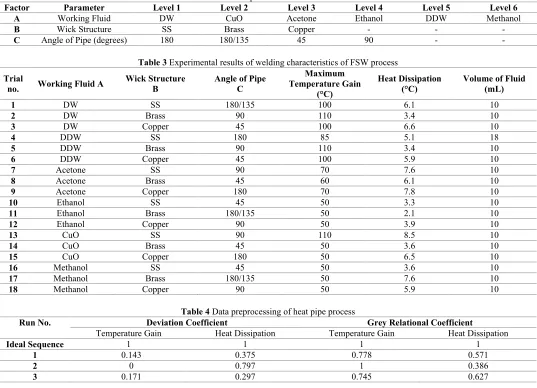
Table 2 Process parameters and their levels
Factor Parameter Level 1 Level 2 Level 3 Level 4 Level 5 Level 6
A Working Fluid DW CuO Acetone Ethanol DDW Methanol
B Wick Structure SS Brass Copper - - -
C Angle of Pipe (degrees) 180 180/135 45 90 - -
Table 3 Experimental results of welding characteristics of FSW process Trial
no. Working Fluid A Wick Structure B Angle of Pipe C
Maximum Temperature Gain
(°C)
Heat Dissipation
(°C) Volume of Fluid (mL)
1 DW SS 180/135 100 6.1 10
2 DW Brass 90 110 3.4 10
3 DW Copper 45 100 6.6 10
4 DDW SS 180 85 5.1 18
5 DDW Brass 90 110 3.4 10
6 DDW Copper 45 100 5.9 10
7 Acetone SS 90 70 7.6 10
8 Acetone Brass 45 60 6.1 10
9 Acetone Copper 180 70 7.8 10
10 Ethanol SS 45 50 3.3 10
11 Ethanol Brass 180/135 50 2.1 10
12 Ethanol Copper 90 50 3.9 10
13 CuO SS 90 110 8.5 10
14 CuO Brass 45 50 3.6 10
15 CuO Copper 180 50 6.5 10
16 Methanol SS 45 50 3.6 10
17 Methanol Brass 180/135 50 7.6 10
18 Methanol Copper 90 50 5.9 10
Table 4 Data preprocessing of heat pipe process
Run No. Deviation Coefficient Grey Relational Coefficient
Temperature Gain Heat Dissipation Temperature Gain Heat Dissipation
Ideal Sequence 1 1 1 1
1 0.143 0.375 0.778 0.571
2 0 0.797 1 0.386
4 0.071 0.53 0.412 0.485
5 0.029 0.797 0.946 0.386
6 0.157 0.406 0.761 0.552
7 0.60 0.141 0.455 0.781
8 0.714 0.375 0.412 0.571
9 0.571 0.1094 0.467 0.821
10 0.929 0.813 0.35 0.381
11 0.857 1 0.368 0.333
12 1 0.719 0.333 0.410
13 0.714 0 0.875 1
14 0.786 0.766 0.389 0.395
15 0.886 0.313 0.361 0.615
16 0.743 0.766 0.402 0.395
17 0.829 0.141 0.376 0.780
18 0.943 0.406 0.347 0.552
Table 5 Deviation and Grey relational coefficients of thermal characteristics of a heat pipe
Run No.
FSW Control Factors Experimental Results Normalized Data
W
orki
ng
Flu
id A
Wi
ck
St
ruc
ture B
A
ngl
e of
Pi
pe C
Tem
per
at
ur
e
Ga
in
(°C) Heat
D
iss
ip
atio
n
(°C)
Tem
per
at
ur
e
Ga
in
(°C) Heat
D
iss
ip
atio
n
Ideal Sequence 1 1
1 DW SS 180/135 100 6.1 0.857 0.625
2 DW Brass 90 110 3.4 1 0.203
3 DW Copper 45 100 6.6 0.829 0.703
4 DDW SS 180 85 5.1 0.929 1
5 DDW Brass 90 110 3.4 0.971 0.594
6 DDW Copper 45 100 5.9 0.843 0.594
7 Acetone SS 90 70 7.6 0.4 0.859
8 Acetone Brass 45 60 6.1 0.286 0.625
9 Acetone Copper 180 70 7.8 0.429 0.891
10 Ethanol SS 45 50 3.3 0.071 0.188
11 Ethanol Brass 180/135 50 2.1 0.143 0
12 Ethanol Copper 90 50 3.9 0 0.281
13 CuO SS 180 110 8.5 0.929 1
14 CuO Brass 45 50 3.6 0.214 0.234
15 CuO Copper 180 50 6.5 0.114 0.688
16 Methanol SS 45 50 3.6 0.257 0.234
17 Methanol Brass 180/135 50 7.6 0.171 0.859
18 Methanol Copper 90 50 5.9 0.057 0.594
Table 6 Grey relational grade and their rank
Run No. Grey Relational Grade Rank Run No. Grey Relational Grade Rank
1 0.674603 4 10 0.365476 17
2 0.692771 2 11 0.350877 18
3 0.686066 3 12 0.371795 16
4 0.448307 13 13 0.9375 1
5 0.665744 5 14 0.391975 15
6 0.656297 6 15 0.488105 11
7 0.617517 8 16 0.39868 14
8 0.491597 10 17 0.578416 9
9 0.64359 7 18 0.449129 12
Table 7 Mean GRG response
Level Working Fluids, A Wick Structure, B Angle of Pipe, C
1 0.584 0.529 0.69
2 0.753 0.549 0.535
3 0.443 0.574 0.498
5 0.363 - -
6 0.475 - -
Delta 0.391 0.045 0.191
Rank 1 3 2
Fig. 4 Response graphs for S/N ratio and Means (a) working fluids, (b) wick structure and (c) angle pipe
4.3.
Analysis of Variance (ANOVA)
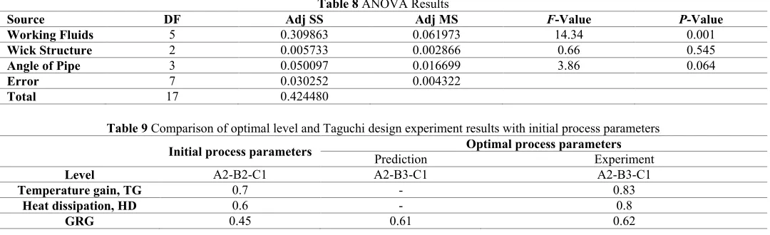
The major or most significant variable affecting the multi-output characteristics can be established by ANOVA using the various quantities shown in Table 8. The percentage contribution of each variable F-ratio and P-values to find significant factors are determined (Yunus et al., 2016). The ANOVA method applied at 95% confidence level for investigating the different levels of significance of process factors on multiple thermal characteristics of the heat pipe. The regression analysis yields an Equation (5) for GRG to obtain most significant factor.
GRG = 0.5659+0.0130*Working Fluids Acetone-0.1285*Working Fluids CuO+0.1819*Working Fluids Ddw+0.1548*Working Fluids Dw-0.1669*Working Fluids Ethanol-0.0542*Working Fluids Methanol-0.0011*Wick Structure Brass-0.0221*Wick Structure Copper+0.0232*Wick Structure Ss+0.1087*Angle of Pipe 180°-0.0162*Angle of Pipe 180°/1350-0.0675*Angle of Pipe 45°-0.0250*Angle of Pipe 90°
(5)
In Table 8, using the Taguchi design method, the optimal process for the best multiple performance characteristics is predicted to be the combination of control factors A2B3C1 which is the case excluding the table of L18 orthogonal arrays. The relative important process factors are ACB. Figure 2 shows the response graph of the grey relational grade, where the larger the grey relational grade, the better the multiple performance characteristics. The effect at A3 and A4 has not much difference. The accuracy of the grey relational grade for optimal combination of process parameters with the significantly affecting multiple performance characteristics can be checked by the statistical method of ANOVA.
4.4.
TP Verification Test
After obtaining the optimum level of the different variables, the concluding measure is to predict the performance characteristic using the optimal level of factors (Yunus et al., 2016).
Γ𝑜𝑜𝑜𝑜𝑜𝑜= Γ𝑚𝑚 + Σ (Γ𝑖𝑖− Γ𝑚𝑚) p𝑖𝑖-1 (6)
The predicted GRG Γ𝑜𝑜𝑜𝑜𝑜𝑜 using the optimal level of process factors
can be determined as where Γi total mean of the GRG at ith level and Γm
mean of the GRG at the optimal level, and p number of process factors that significantly affect the multiple performance characteristics. Based on Equation (6), predicted value of GRG for optimal setting of control variables of thermal performance of a heat pipe obtained are shown in Table 9. The results of the verification test were temperature gain of 0.8 and heat dissipation of 0.7. The confirmation test result obtained exhibited better than the experimental results in Table 3.
5.
CONCLUSION
decreases by a large amount for Nano fluid. It is concluded that the circular heat pipe using nano-fluid as the working fluid can give the most promising results compared with normal base working fluids.
A GRG obtained from the GRA analysis was used to optimize the control variables of conventional heat pipe thermal performance characteristics (heat capacity and temperature gain). From the mean response table of the Taguchi method, the highest value of the GRG is achieved for the working fluid of cupric oxide, wick structure of Stainless
steel and pipe angle of 180° for thermal characteristics of a heat pipe which are the recommended levels. ANOVA of GRG showed that the working fluid has constituted the most significant control variable. Therefore, the Taguchi based GRA method can be applied for the multi response optimization of control variables to improve the process efficiency of a heat pipe.
Table 8 ANOVA Results
Source DF Adj SS Adj MS F-Value P-Value
Working Fluids 5 0.309863 0.061973 14.34 0.001
Wick Structure 2 0.005733 0.002866 0.66 0.545
Angle of Pipe 3 0.050097 0.016699 3.86 0.064
Error 7 0.030252 0.004322
Total 17 0.424480
Table 9 Comparison of optimal level and Taguchi design experiment results with initial process parameters
Initial process parameters Prediction Optimal process parameters Experiment
Level A2-B2-C1 A2-B3-C1 A2-B3-C1
Temperature gain, TG 0.7 - 0.83
Heat dissipation, HD 0.6 - 0.8
GRG 0.45 0.61 0.62
REFERENCES
Ahmad, H.H., and Rajab, R.H., 2010, "An Experimental Study of Parameters Affecting a Heat Pipe. Al-Rafidain Engineering," Al-Rafidain Engineering, 18(3), 97-116.
Bozorgan, N., Krishnakumar, K., and Bozorgan, N., 2012, "Numerical Study on Application of CuO-Water Nanofluid in Automotive Diesel Engine Radiator," Modern Mechanical Engineering, 2(4), 130-136.
http://dx.doi.org/10.4236/mme.2012.24017
Chi, S.W., 1976, Heat Pipe Theory and Practice: A Sourcebook (Series in thermal and fluids engineering). Washington, DC, McGraw-Hill Inc., US.
Cotter, T.P., 1967, “Heat pipe startup dynamics,” Proc. of SAE Thermionic Conversion Specialist Conference, Palo Alto, CA.
E2109-01, A., 2014, Standard Test Methods for Determining Area Percentage Porosity in Thermal Sprayed Coatings, West Conshohocken, PA, ASTM International.
Faghri, A., Zhang, Y., and Howell, J., 2010, Advanced Heat and Mass Transfer, Global Digital Press.
Gaugler, R.S., 1944, Heat transfer device. USA, Google Patents. US2350348 A.
Kamble, D.P., Gadhave, P.S., and Anwar, M.A., 2014, "Enhancement of Thermal Performance of Heat Pipe Using Hybrid Nanofluid," International Journal of Engineering Trends and Technology (IJETT), 17(9), 425-428.
http://dx.doi.org/10.14445/22315381/IJETT-V17P283
Kang, S.W., Wei, W.C., Tsai, S.H., and Yang, S.Y., 2006, "Experimental investigation of silver nano-fluid on heat pipe thermal performance," Applied Thermal Engineering, 26(17), 2377-2382.
http://dx.doi.org/10.1016/j.applthermaleng.2006.02.020
Korn, F., 2008, Project Report 2008 MVK160 Heat and Mass Transport (Heat pipes and its applications). Lund, Sweden, Dept. of Energy Sciences, Faculty of Engineering, Lund University.
Launay, S., Sartre V., and Bonjour J., 2007, "Parametric analysis of loop heat pipe operation: a literature review," International Journal of Thermal Sciences, 46(7), 621-636.
http://dx.doi.org/10.1016/j.ijthermalsci.2006.11.007
Lin, Y.H., Kang, S.W., and Chen, H.L., 2008, "Effect of silver nano-fluid on pulsating heat pipe thermal performance," Applied Thermal Engineering, 28(11), 1312-1317.
http://dx.doi.org/10.1016/j.applthermaleng.2007.10.019
Liu, Z. and Zhu, Q., (2011), "Application of aqueous nanofluids in a horizontal mesh heat pipe," Energy Conversion and Management 52(1), 292-300.
http://dx.doi.org/10.1016/j.enconman.2010.07.001
Ma, H. B., Wilson, C., Borgmeyer, B., Park, K., Yu, Q., Choi, S. U. S., and Tirumala, M., 2006, "Effect of nanofluid on the heat transport capability in an oscillating heat pipe," Applied Physics Letters,88(14), 143116.
https://doi.org/10.1063/1.2192971
Manimaran, R., Palaniradja, K., Alagumurthi, N., and Hussain, J., 2012, "Factors affecting the thermal performance of heat pipe," Journal of Engineering Research and Studies, 3(2), 20-24.
Mozumder, A. K., Akon, A. F., Chowdhury, M. S. H., and Banik, S. C., 2010, "performance of heat pipe for different working fluids and fill ratios." Journal of Mechanical Engineering, 41(2), 96-102.
https://doi.org/10.3329/jme.v41i2.7473
Ochterbeck, J. M., 2003, Heat pipes in Heat Transfer Handbook. Septiadi, W. N., Putra, N., Juarsa, M., Putra, I. P. A., and Sahmural, R., 2013, "Characteristics of Screen Mesh Wick Heat Pipe with Nanofluid as Passive Cooling System, " Atom Indonesia, 39(1), 24-31.
Trefethen, L., 1962, “On the Surface Tension Pumping of Liquids or a Possible Role of the Candlewick in Space Exploration,” General Electric Tech. Inform., S. N. D114.
Vasiliev, L. L. 2005. "Heat pipes in modern heat exchangers," Applied Thermal Engineering, 25(1), 1-19.
Yunus, M., and Alsoufi, M. S., 2015, "A Statistical Analysis Of Joint Strength Of Dissimilar Aluminium Alloys Formed By Friction Stir Welding Using Taguchi Design Approach, ANOVA for the Optimization of Process Parameters," IMPACT: International Journal of Research in Engineering & Technology (IMPACT: IJRET), 3(7), 63-70.
Yunus, M., and Alsoufi, M.S., 2016, "Experimental Investigations on Precision Machining of Thermal Barrier Coatings and Application of the Grey Relation Approach to Determine the Optimum Process Parameters," High Temperature Material Processes: An International Quarterly of High-Technology Plasma Processes, 20(4), 333-354.
http://dx.doi.org/10.1615/HighTempMatProc.2017019985
Yunus, M., and Alsoufi, M.S., 2016, "Multi-Objective Optimization of Joint Strength of Dissimilar Aluminum Alloys Formed by Friction Stir Welding Using Taguchi-Grey Relation Analysis, " International Journal of Engineering & Technology IJET-IJENS 16(04), 10-17.
Yunus, M., and Alsoufi, M.S., 2016, "Multi-output optimization of tribological characteristics control factors of thermally sprayed industrial
ceramic coatings using hybrid Taguchi-grey relation analysis," Friction, 4(3), 208-216.
http://dx.doi.org/10.1007/s40544-016-0118-6
Yunus, M., and Alsoufi, M.S., 2017, "Post-Processing of Ceramic Oxide and Metallic Coated Surfaces using Microwave Glazing," High Temperature Material Processes: An International Quarterly of High-Technology Plasma Processes 21(1), 37-52.
http://dx.doi.org/10.1615/HighTempMatProc.2017020399
Yunus, M., and Alsoufi, M.S., and Munshi, S.M., 2016, "Taguchi-Grey relation analysis for assessing the optimal set of control factors of thermal barrier coatings for high temperature applications," Mechanics of Advanced Materials and Modern Processes, 2(1), 4.
https://doi.org/10.1186/s40759-016-0011-z