DESIGN AND SIMULATION OF PARALLEL MICROHEATER
Shailendra K. Tiwari
a,*, Somashekara Bhat
a, Krishna K. Mahato
b, Bharath B. Manjunath
ca Department of E. C. E, Manipal Institute of Technology, Manipal Academy of Higher Education, Manipal, Karnataka, 576104, India b School of Life Sciences, Manipal Academy of Higher Education, Manipal, Karnataka, 576104, India
c Manipal Technologies Ltd, Manipal, Karnataka, 576104, India
A
BSTRACTThis paper presents the design and simulation of a thin film microheater. This can have promising applications in bio-medical analysis, explosive detection, gas sensing, and micro-thrusters. An approach is presented to enhance the thermal uniformity of parallel microheater. The modeling of microheater is done using glass as a substrate material. The analysis is carried out with different resistive material for the heater. To study the response of the microheater to the different supply voltage, substrate thickness, and time interval, finite element simulation is carried out with commercial FEM analysis tool- COMSOL Multiphysics 5.2a. The proposed design in Model 1 have high contact resistance and it suffers from the contact-heating problem; however, Model 2 offers an excellent thermal uniformity with a tolerance of 1°C. There is a good agreement between the simulated and the theoretical results.
Keywords: Joule-heating, Microheater, Resistive-heating, Sensor, Temperature.
* Corresponding author. Email: sk.tiwari@manipal.edu
1. INTRODUCTION
Most of the bio-medical analysis and sensing applications require an elevated temperature. Therefore, systems like microfluidic Polymerase Chain Reaction (PCR) chip, gas sensors, and micro-chemical sensors need an integrated heating component with the device. Microheaters are one of the most important functional blocks for the systems such as microfluidic PCR chip for bio-medical analysis (Park et al., 2011; Nie,
et al., 2014) humidity sensors for industrial application (Smetana and Unger, 2008; Dai, 2007), and Methanol sensors for chemical sensing (Ha et al., 2005; Korotcenkov, 2014).
There are two types of microheater: the wire and the thin film based. The thin film microheaters are preferred over the wire microheaters due to their low thermal mass, less power consumption and ease of integration with other functional units of the system. At the early stage, heavily p-doped silicon microheaters were used because of its compatibility with integrated circuit fabrication process and its attractive mechanical properties. However, huge power consumption is the major drawback of the silicon microheaters. To overcome the problem of large power requirement, the proposed heaters are modeled on the Glass substrate, which offers low thermal conductivity (1.38 Wm-1°C-1) and high electrical resistivity (1 ×10¹⁴Ωm); desirable to achieve better thermal uniformity and low power consumption.
The commonly used resistive materials for the microheater are Aluminum (Phanakun et al., 2012), Copper (Pandya et al., 2012), Gold (Kim, 2006), Nickel-Chromium (NiCr) alloy (Das and Akhtar, 2014), Platinum(Hsieh et al., 2008), Titanium(Guan and Puers, 2010), and Tungsten(Santra et al., 2010). Aluminum and Copper are susceptible to corrosion and oxidation; therefore, they are avoided as the resistive material for the microheater. Gold and Platinum are chemically inert materials but they are very expensive; therefore, to keep the device cost low, they are not used. The melting temperature of Titanium and Tungsten are higher compared to NiCr. Therefore, it is easier to
evaporate the NiCr compared to Titanium and Tungsten. Hence, this work uses NiCr as a resistive element for the microheater. Figure 1 shows the schematic of microheaters.
Fig. 1Schematic of (a) series, and (b) parallel microheater
2. DESIGN AND GOVERNING EQUATIONS
Joule heating is the phenomena in which the current is passed through a resistive material to generate the heat. The heating power P of a microheater is produced by connecting a voltage source V across the two ends of a heating circuit with a resistance R due to the current I. The basic configurations of the heating circuit are categorized as series and parallel type, respectively. Figures 1(a) and 1(b), shows the series and parallel resistance microheater, respectively. In Fig. 1(a), the contact pad and the resistive elements are connected in series. Therefore, power dissipation of the heater is given by,
2
PI R (1)
From Eq. (1) the power is directly proportional to the resistance of the heating element. Therefore, the higher resistance values are favorable in achieving the large heating power.
In Fig. 1(b) there is no voltage difference in the resistive element across the line 1-1' therefore the power across 1-1' line is given by,
Frontiers in Heat and Mass Transfer
2
V P
R
(2)
Hence, the smaller resistances are favorable in achieving higher heating power and results in the faster response for the parallel configuration.
Resistance plays a critical role in power dissipation calculation. The resistance of any thin-film having the length, width and thickness
L, w, and t, respectively is given by,
L R
wt
(3)
The ρ represents the resistivity of the material. If L=w, then Eq. (3) represent the sheet resistance (RS) of the resistive layer and can be written as,
S
R t
(4)
Therefore, the resistance of any resistive thin film can be calculated as,
S
L
R R
w
(5)
The heat produced in a resistive element due to Joule heating is given by,
2
Q I R t
(6)
Here, ∆t is the time. The heat generated by the microheater is dissipated in the surrounding medium. The thermal loss of microheater is divided into three types, viz., conduction in the device, convection cooling, and radiation. Therefore, to achieve steady state, the total heat produced by the microheater must be equal to the heat lost by conduction (Qcond), convection (Qconv), and radiation (Qrad).
2
cond conv rad
I R t Q Q Q (7)
2 Qcond Qconv Qrad
I R
t t t
(8)
The rate of heat loss by conduction in the glass substrate is given by,
cond glass glass Q T k A t x
(9)
Here kglass, Aglass, ∆T, and ∆x, represents the thermal conductivity, area of the cross-section of the glass substrate, a temperature difference of two opposite surfaces and the thickness of glass substrate, respectively. The rate of heat loss by conduction can be reduced by selecting the substrate material with a lower thermal conductivity and by decreasing the area of conduction.
The rate of heat loss by convection in the air is given by,
conv conv
Q
hA T
t
(10)
Here, h is coefficient of convection, it depends on the geometrical factor, shape, and the orientation of the heated surface. Aconv and ∆T represent the surface area through which convection is taking place and the temperature difference between the heater and the ambient, respectively.
The rate of heat lost by radiation is given by,
4
rad
rad
Q
A T
t
(11)
The ε, σ, Arad, and ∆T are the emissivity, Stefan Boltzmann constant, surface area and the temperature difference between the heater and the ambient, respectively.
Therefore, the total power lost can be obtained by,
2 4
glass glass conv rad
T
I R k A hA T A T
x
(12)
The losses due to radiation can be neglected at the temperature range of interest of microheater and due to the very low emissivity of the materials involved (Courbat et al., 2011). Therefore Eq. (12) can be rewritten as
2
glass glass conv
T
I R k A hA T
x
(13)
Fig. 2Parallel microheater (Model 1)
Figure 2 shows the parallel microheater Model 1, the width of all the resistive elements RA to RE is taken 40µm. For the resistance calculation, the resistivity and thickness of all the resistive films are taken as 1.10×10⁻⁶ Ωm and 0.2µm, respectively. The dimension and theoretical resistance values of all the resistive element used in Model 1 are given in Table 1.
Table 1 Resistance of individual resistive elements of microheater Model 1.
Parameter L(µm) w(µm) L/w Resistance (Ω) RA 10380 40 259.5 1427.25
RB 10000 40 250.0 1375.00
RC 10000 40 250.0 1375.00
RD 240 40 6 33.00
RE 100 40 2.5 13.75
RF 500 500 259.5 5.50
between RC and RB is 200µm whereas the separation of RB and RA is 150µm.
Fig. 3Modified parallel microheater (Model 2)
To overcome the problem of nonuniform heating of Model 1, a modified parallel microheater is proposed in Model 2 shown in Fig. 3. In the Model 2, the resistance of the resistive elements is selected in such that if a voltage source connected to the heater the minimum current (I) flows through the resistance RC1, and as we move away from the center in the top or bottom direction current gets doubled of its neighboring branch.
The heating power in resistive element RC1 can be calculated as,
1
2
1 C
R
L
P I
w t
(14)
Here L and w1 represent the length and width of resistance RC1. Similarly, the power in resistive element RB1 due to current 2I can be calculated as,
1
2
2
4
B
R
L
P I
w t
(15)
Here w2 represent the width of resistive element RB1. By equating Eqs. (14) and (15), and solving for w2
2 4 1
w w (16)
Similarly, the width of all the resistive elements is calculated by taking a constant length 10000µm and shown in Table 2.
Table 2 Resistance of individual resistive elements of microheater Model 2 with a fixed length.
Parameter L(µm) w(µm) L/w Resistance (Ω) RA1 10000 640 15.62 85.91
RB1 10000 140 62.50 343.75
RC1 10000 40 250.00 1375.00
RD1 10000 1440 6.95 38.22
RE1 10000 1960 5.10 38.30
Once the L:w ratio of all the resistances are known, then as per spacing between the resistive elements of Model 2 shown in Fig. 3, the dimensions of all the resistive members are calculated using Eq. (5), and given in Table 3.
As per the calculation, the length and width of RE1 are 5355µm and 1050µm, respectively. But to accommodate the heater on a 30×10mm2 glass substrate, the length of R
E1 is fixed to 1554µm. The major drawback of the design proposed in Model 2 is if the number of parallel branches increases the width of the resistive elements increases
exponentially. Hence for more than 5 parallel branches, the proposed design is not practical.
Table 3 Resistance of individual resistive elements of microheater Model 2.
Parameter L(µm) w(µm) L/w Resistance (Ω) RA1 11580 741.12 15.62 85.91 RB1 9102 145.90 62.50 343.75 RC1 9120 36.50 250.00 1375.00
RD1 380 54.67 6.95 38.22
RE1 5355 1050 5.10 38.30
3. SIMULATION
The simulations are carried out using a commercial FEM simulation tool COMSOL Multiphysics 5.2a. The specifications of the Model 1 and Model 2 are shown in Table 4.
Table 4 Microheater specification.
Specification Model 1 Model 2
Substrate (L×w (mm2)) 20×10 30×10 Substrate thickness(mm) 1.5 1.5 Substrate material Glass Glass Contact pad (mm2) 0.5×0.5 1.554×1.050 Minimum line width (µm) 40 36.5 Maximum line width (µm) 40 1050 Resistive material NiCr NiCr Resistive layer thickness (µm) 0.2 0.2
Fig. 4Mesh model of microheater (a) Model 1, and (b) Model 2
4. RESULT AND DISCUSSION
The simulation of Model 1 and Model 2 are carried out using Aluminium, Copper, Gold, Nickel-Chromium, Platinum, Titanium and Tungsten. For all the simulation Glass (1.5mm thick) is taken as substrate. To find the resistance of microheaters modeled with the different resistive material, 1A current is applied as the input to each model and the voltage across each heater is measured. From Ohm's law, we know that V=IR, therefore, the voltage is equal to the resistance of the heater. Once the resistance is known, by applying the fixed voltage across the heater, the power is calculated for Model 1 and Model 2 and given in Tables 5 and 6, respectively.
Table 5 Simulation outcome of Model 1.
Material Resistance(Ω) Voltage(V) Power(W) Time(s)
Al 8.57 0.73 0.0621 1476
Au 6.67 0.58 0.0504 1410
Cu 5.24 0.68 0.0642 1455
NiCr 335.00 4.70 0.0659 1452
Pt 34.20 1.45 0.0614 1472
Ti 117.00 2.80 0.0670 1440
W 15.20 1.00 0.0657 1466
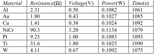
Table 6 Simulation outcome of Model 2.
Material Resistance(Ω) Voltage(V) Power(W) Time(s)
Al 2.31 0.50 0.1082 1061
Au 1.80 0.43 0.1027 1085
Cu 1.41 0.38 0.1024 1092
NiCr 90.3 3.20 0.1134 1079
Pt 9.23 1.00 0.1083 1093
Ti 31.6 1.80 0.1025 1090
W 4.11 0.67 0.1092 1075
Once the power is known the time required to reach to the steady state temperature is calculated theoretically for microheater Model 1 and Model 2, and given in Table 5 and Table 6, respectively.
Figures 5 and 6 shows the time versus temperature plot for microheater Model 1 and Model 2, respectively. It is observed from the Tables 5, 6 and Figs. 5 and 6 that there is a good agreement between the theoretically calculated time required to reach to the given steady state temperature and the result obtained from the FEM simulation. Figures 7 and 8 shows the zoomed view of time versus temperature plot shown in Figs. 5 and 6, respectively. It is observed that to reach the steady state temperature microheater Model 1 takes longer time compared to Model 2 (Cengel and Ghajar, 2011).
Fig. 5Time vs. temperature plot of Model 1
Fig. 6Time vs. temperature plot of Model 2
Fig. 7Zoomed view of time vs. temperature plot of Model 1
Fig. 8Zoomed view of time vs. temperature plot of Model 2
Focusing on PCR application, simulation have been carried out to find the time required to reach to the temperatures 90-95°C (denaturation), 50-55°C (annealing), and 70-75°C (extension) steady state temperature for the NiCr microheater Model 1 (Fig. 9) and Model 2 (Fig. 10), It is observed from the Figs. 9 and 10 that time required for lower steady state temperature is less compared to the elevated temperature and rate of change of temperature is more for the higher steady state temperature.
2) initially 9V input is applied and after the 50s it is reduced to 3V, the time versus temperature plot of Model 1 and Model 2 are shown in Figs. 11 and 12, respectively. From Figs. 11 and 12, it is observed that both the heaters achieve the 90 percent of steady state temperature in less than 200s. The problem involves in this approach is the kink in the temperature during the voltage transition. It is observed that Model 2 (Fig. 12) has smaller temperature kink compared to Model 1 (Fig. 11), it is due to larger size of contact-pad.
Fig. 9Time vs. temperature plot of NiCr microheater Model 1
Fig. 10Time vs. temperature plot of NiCr microheater Model 2
Fig. 11Time vs. temperature plot of NiCr microheater Model 1 for step input voltage
Fig. 12Time vs. temperature plot of NiCr microheater Model 2 for step input voltage
Figure 13 shows the isothermal contour plot of NiCr microheater Model 1, the two-green rectangle marked as A and B (resistor RE, Fig. 2), are the hottest point of the heater and circumferences are at a minimum at minimum temperature. The Bar graph is shown in Fig. 14 shows the temperature of hottest and coolest region of microheater Model 1. It is observed the average temperature difference is around 6.5°C for the different resistive material based heater.
Fig. 13Isothermal contour of microheater Model 1
Figure 15 shows the isothermal contour of NiCr microheater Model 2. The bar graph is shown in Fig. 16 shows the temperature of hottest and coolest region of microheater Model 2. It is observed the average temperature difference is around 1°C for the different resistive material based heater. Hence modified parallel heater proposed in Model 2 offers excellent thermal uniformity with the tolerance of 1°C.
Fig. 15Isothermal contour of microheater Model 2
Fig. 16Maximum and minimum temperature vs resistive material for microheater Model 2
Fig. 17Time versus temperature plot of Model 1 for different substrate thickness
Fig. 18Time versus temperature plot of Model 2 for different substrate thickness
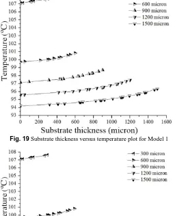
Fig. 19Substrate thickness versus temperature plot for Model 1
For the applications such as PCR, the temperature control is very crucial, the heater and the microfluidic reservoir are fabricated at the opposite surface of the glass substrate. Therefore, it is necessary to carry out the transient analysis to find the time required for the heater to reach to the steady state temperature and the temperature difference of the two opposite faces of the glass substrate. Figures 17 and 18 show the time required to reach the steady state temperature for different substrate thicknesses for Model 1 and Model 2, respectively. It can be observed that as the substrate thickness increases the time required to reach the steady state temperature also increases. Therefore, thinner substrates are favorable for achieving steady state temperature quickly.
Figures 19 and 20 show the substrate thickness versus temperature plot for Model 1 and Model 2, respectively. In the Figs. 19 and 20, x=0 represents the bottom surface of the glass substrate and the terminal value of the x represents surface where the heater is located. It is observed from the Figs. 19 and 20 that the thinner substrate gives the better temperature control.
Table 7 shows the comparison of the present work with the experimental work with respect to the substrate used, heating element, maximum operating temperature, and power. The proposed heater in Model 2 is the most power efficient.
Table 7 Comparison of the present work with the experimental work
Work Substrate Heating
material T(°C) Power(mW)
Present work Glass NiCr 98 65.9
(Model 1)
Present work Glass NiCr 98 113.0
(Model 2) Hsieh et al., 2008 Glass Pt/Ti 94 240.0 Hwang et al., 2011 Silicon Poly-Si 460 250.0
Kundu et al., 2014 Silicon
Boron diffused Si
127 1700.0
5. CONCLUSIONS
The design and the simulation of a microheater have been carried out with two microheater models. Higher values of the thermal and the electrical resistivity are the desirable ones for the substrate to achieve the better heat confinement. The Model 1 and the Model 2 are the parallel type of microheater. Simulations are carried out using varied materials and found that the NiCr microheaters are using comparatively high power but it is cost-effective compared to other material based microheaters. Model 1 suffers overheating of contact pads due to higher resistance and current near the contact pads. To solve this problem microheater Model 2 is proposed. This offers an excellent thermal uniformity with more than 72 percent area of the heater falling within the tolerance of 1°C and most suitable for applications such as stationary PCR.
ACKNOWLEDGEMENTS
This work is supported by National Program on Micro And Smart Structures (NPMASS).
NOMENCLATURE
Aconv surface area of convection (m2)
Aglass area of conduction (m2)
Arad surface area of radiation (m2)
I current (A)
h coefficient of convection(W/m2.°C)
kglass thermal conductivity of glass (W/m.°C)
L length of resistive material (m)
P power (W)
PRB1 power dissipation in resistance RB1 (W)
PRC1 power dissipation in resistance RC1 (W)
Qcond heat loss due to conduction (J)
Qconv heat loss due to convection (J)
Qrad heat loss due to radiation (J)
R resistance (Ω)
RA-RF resistance of heater Model 1 (Ω)
RA1-RE1 resistance of heater Model 2 (Ω)
RS sheetresistance (Ωm)
t thickness of resistive material (m)
T temperature (°C)
V voltage (V)
w width of resistive element (m)
w1-w2 width of resistive element (m)
∆Q total heat generated (J)
∆t time (s)
∆T temperature difference (°C)
∆x thickness of glass substrate (m)
Greek Symbols
ε total emissivity
ρ resistivity (Ωm)
σ Stefan-Boltzmann constant (W/m2 ·°C 4)
REFERENCES
Cengel, Yunus A. and Afshin J. Ghajar, 2011, Heat and Mass Transfer: Fundamentals and Applications, 5th ed., McGraw-Hill Education, New York.
Courbat, J., Canonica , M., Teyssieux, D., Briand, D., and De Rooij, N. F., 2011, “Design and Fabrication of Micro-Hotplates Made on a Polyimide Foil: Electrothermal Simulation and Characterization to Achieve Power Consumption in the Low mW Range,” Journal of Micromechanics and Microengineering21(1), 1–11.
https://doi.org/10.1088/0960-1317/21/1/015014
Dai, C. L., 2007, “A Capacitive Humidity Sensor Integrated with Micro Heater and Ring Oscillator Circuit Fabricated by CMOS-MEMS Technique,” Sensors and Actuators, B: Chemical122(2), 375–380.
https://doi.org/10.1016/j.snb.2006.05.042
Das, S., Akhtar, J., 2014, "Comparative Study on Temperature Coefficient of Resistance (TCR) of the E-beam and Sputter Deposited Nichrome Thin Film for Precise Temperature Control of Microheater for MEMS Gas Sensor," In: Jain, V., Verma, A. (eds) Physics of Semiconductor Devices. Environmental Science and Engineering. Springer, Cham.
https://doi.org/10.1007/978-3-319-03002-9_124
Guan, T. and Puers, R., 2010, “Thermal Analysis of a Ag/Ti Based Microheater,” Procedia Engineering5, 1356–1359.
http://dx.doi.org/10.1016/j.proeng.2010.09.366
Ha, S. C., Kim, Y. S., Yang, Y., Kim, Y. J., Cho, S. M., Yang, H. and Kim, Y. T., 2005, “Integrated and Microheater Embedded Gas Sensor Array Based on the Polymer Composites Dispensed in Micromachined Wells,” Sensors and Actuators, B: Chemical105(2), 549–555.
https://doi.org/10.1016/j.snb.2004.01.019
Hsieh, T. M., Luo, C. H., Huang, F. C., Wang, J. H., Chien, L. J. and Lee, G. B., 2008, “Enhancement of Thermal Uniformity for a Microthermal Cycler and Its Application for Polymerase Chain Reaction,” Sensors and Actuators, B: Chemical130(2), 848–856.
https://doi.org/10.1016/j.snb.2007.10.063
Hwang, W. J., Shin, K. S., Roh, J. H., Lee, D. S., and Choa, S. H., 2011, “Development of Micro-Heaters with Optimized Temperature Compensation Design for Gas Sensors,” Sensors11(3), 2580–2591.
Kim, Y. S., 2006, “Microheater-Integrated Single Gas Sensor Array Chip Fabricated on Flexible Polyimide Substrate,” Sensors and Actuators, B: Chemical114(1), 410–417.
https://doi.org/10.1016/j.snb.2005.06.016
Korotcenkov, G., 2014, Handbook of Gas Sensor Materials. 1st ed. Springer International Publishing, New York.
https://doi.org/10.1007/978-1-4614-7165-3
Kundu, P., Bhattacharyya, T. K., and Das, S., 2014, “Electro-Thermal Analysis of an Embedded Boron Diffused Microheater for Thruster Applications,” Microsystem Technologies20(1), 23–33.
https://doi.org/10.1007/s00542-013-1759-2
Nie, J., Zhao, Y., and Peng, N., 2014, “Multichannel Oscillatory-Flow PCR Micro-Fluidic Chip with Controllable Temperature Gradient,”
Microsystem Technologies21(1), 41–48.
https://doi.org/10.1007/s00542-014-2077-z
Pandya, H. J., Sudhir Chandra, and Vyas, A. L., 2012, “Integration of ZnO Nanostructures with MEMS for Ethanol Sensor.” Sensors and Actuators, B: Chemical161(1), 923–28.
http://dx.doi.org/10.1016/j.snb.2011.11.063
Park, S., Zhang Y., Lin, S., Wang, T. H., and Yang S.. 2011. “Advances in Microfluidic PCR for Point-of-Care Infectious Disease Diagnostics,”
Biotechnology Advances29(6), 830–39.
http://dx.doi.org/10.1016/j.biotechadv.2011.06.017
Phatthanakun R., Deekla P., Pummara W., Sriphung C., Pantong C. and Chomnawang N., 2012, “Fabrication and Control of Thin-Film Aluminum Microheater and Nickel Temperature Sensor.”112–15 in
2012 7th IEEE International Conference on Nano/Micro Engineered and Molecular Systems (NEMS).
https://doi.org/10.1109/ECTICON.2011.5947758
Santra, S., Udrea, F., Guha, P. K., Ali, S. Z., and Haneef, I., 2010, “Ultra-High Temperature (>300 °C) Suspended Thermodiode in SOI CMOS Technology,” Microelectronics Journal 41(9), 540–46.
http://dx.doi.org/10.1016/j.mejo.2009.12.005
Smetana, W. and Unger, M., 2008, “Design and Characterization of a Humidity Sensor Realized in LTCC-Technology,” Microsystem Technologies14(7), 979–87.