Vol.9 (2019) No. 2
ISSN: 2088-5334
Effect of Heat Treatment Process on The Microstructure and
Mechanical Properties of The Spray Coating Ni-Cr on CT38 Steel
Anh Tuan Hoang
#, Thi Thanh Van Tran
+, Van Bach Nguyen
+, Duong Nam Nguyen
+,* #Ho Chi Minh city University of Transport, Ho Chi Minh city, Vietnam E-mail: [email protected]
+
Vietnam Maritime University, Haiphong, Vietnam
E-mail: * [email protected]
Abstract— The thermal spray has been commonly used in several applications to replace the plating technology due to high adhesion,
low cost, and environmental pollution. The thermal coating is usually used to rehibilitate the small disrepair of the crankshaft but the dimension and mechanical properties of such parts are still maintaned. Commonly, the microstructure and mechanical properties are greatly affected by depth of thermal coating, and thermal coating needs to be conducted the heat treatment to homogenize the microstructure between metals of coating and base metals as well as to improve the adhesion, hardness, and wear intensity. In this work, the effects of heat treatment on the microstructure and mechanical properties of the coating layer based on 80Ni-20Cr onto the surface of CT38 steel were conducted. SEM images and EDS analysis were used to determine the distribution of elements before and after heat treatment. In addition, mechanical properties such as Vicker hardness (HV), wear intensity, and adhesion were practically measured. As a result, after heat treatment by annealing under 1100oC during 8h, HV and adhesion were significantly higher than the case of non-heat treatment; meanwhile, wear intensity was found with 3 times lower compared to the unheated sample. The strong bi-lateral diffusion between Cr from coating layer and C from CT38 steel component to form carbide along with a formation of bond Ni-Fe was thought to be the main cause resulting in the improvement of mechanical properties and was demonstrated in this study.
Keywords—thermal spray; heat treatment; microstructure; mechanical properties.
I. INTRODUCTION
Metal-spraying technology was invented by Swiss engineer Max Ulrich Schoop in the early 20th century. The principle of this technology is to use heat (arc, gas, plasma) to molten metal. After that, the liquid metal is inflated with compressed air to disperse into very fine particles (fog), firing on the prepared surface (cleaning, sanding) to create a metallic coating with required thickness, in which the metal particles overlap each layer. Besides the technologies for the surface treatment to improve the capacity of abrasion and deformation resistance, corrosion resistance such as heat treatment [1], chemical/diffusion-heat treatment [2], [3], mechanical-heat treatment [4], [5], and alloying [6], metal-spraying technology has become a separate technology field that has been also expressed as a surface-processing technology.
Based on DIN EN657 standard, the thermal spray (TS) process may be classified according to the applied energy source as followed [7]: (i)-melt atomization-based TS (for example, MB-melt bath); (ii)-gaseous/liquid fuels -based TS
such as DG-detonation gun, WF-wire flame, PF-powder flame, HVWF-high velocity wire flame, HVOF-high velocity oxy-fuel; (iii)-expansion of compressed gases without combustion-based TS (i.e. CG-cold gas); (iv)-electrical arc/gas discharge-based TS including A-arc, SA-shrouded arc, AP-atmospheric plasma, SP-SA-shrouded plasma, VP-vacuum plasma, HPP-high pressure plasma, LSP-liquid stabilized plasma, ICP-inductively coupled plasma; (v)-beams of high energy density-based TS such as laser. In the TS technology, the metal is heated molten or high-deformability state after feeding inside/outside the spraying gun to propel onto the unmolten surface with high-velocity to form the new joinder based on the adhesion of metal-spraying [8].
fatigue property compared to hard-chromium plating in the aircraft manufacturing application [10]. TS coatings based on Cr3C2/Ni-Cr or WC in the combination of HVOF
technique were reported as the best alternative method to plating due to good wear and high corrosion resistance [11], [12]. The HVOF-based spraying technique showed a high tightness of metal, and cermet coatings can thus have a better oxidation resistance, a higher adhesion, and faster deposition rates than other processes [13]. Coatings created by chromium carbide after being added various metallic binders, however, Ni-Cr was considered as the main binder, were widely and commonly utilized in engineering field because of highly chemical stability, good tribological properties, workability in aggressive environments, oxidation resistance [14].
Moreover, Ni-Cr-based coatings were favorite in applications for aeronautic engineering because they could endure under working conditions with very high temperatures up to over 850°C [15]. In another study, the 50Ni–50Cr coatings were found with excellent protection against the oxidation problem from steam under the duration for the test of 1000 h. The above-mentioned excellent protection of the 50Ni–50Cr was thought due to the film formation based on chromium oxide on the coating surface [16]. A good resistance in the hot corrosion of Ni-Cr(80/20) coatings, especially in molten salts with temperature over 900°C, was also indicated by Sigh et al [17]. In addition, Ni-Cr coatings were also used as a metal matrix in the production of composite coatings which were reinforced with carbides [18], [19]. In the case of Ni-Cr coatings, a faster diffusion compared to the bulk alloy as well as a fast Fe diffusion across the Ni-Cr-based coatings was found in the study of [20].
Obviously, the interaction time between metallic particles with the surrounding environment is very short in the spraying process, then the solidification and cooling rapidly reduce their interaction ability, leading to the shallow diffusion process. Moreover, the bonding of the particle to the substrate mainly depends on the degree of physical bonding, which is the appearance of the contact surface on the contact surface. Spray formation is the sequential process of sequentially dispersing sprayed particles onto the substrate, where sprayed particles contact or contact with the surface without filling the space will cause the porous phenomenon in the coating. The physical contact process does not limit the interaction because the molten particles are rapidly thinned and pressed into the substrate under the action of gravity.
Thus, the next heat treatment process should be applied after the TS process aiming to diffuse the metal-spraying to the base metal as well as to increase the bond and link between the base metal and the metal coating in consideration of a chemical bond, not a mechanical bond, however, the heat treatment only received limited attention. In this work, the coating formed after using 80Ni-20Cr powder for TS process onto the C45 steel surface was conducted. Additionally, the coating layer was thoroughly evaluated and analyzed based on microstructure, wear intensity, hardness, and adhesion before and after heat treatment.
II. MATERIALS AND METHODS
A. Material
In this study, a cylindrical sample with a diameter of 25 mm and height of 220mm was produced by C45 steel that its chemical composition was given in Table 1. The commercial 80Ni-20Cr power with the chemical composition given in Table 2 was used to carry out the thermal spraying experiments. The 80Ni-20Cr power with carbide size of 5-10
μm was used
.
TABLEI
CHEMICAL COMPOSITION OF THE SUBSTRATE C45 STEEL Chemical
composition C Si Mn P S
Overall mass of
Cr-Mo-Ni
% mass, max
0.42-0.50 0.40
0.50-0.80 0.045 0.045 0.63
TABLEII
CHEMICAL COMPOSITION OF NI-CR SPRAY POWDER Chemical composition Ni Cr C
% mass, max 75-68 22-23 < 0,15
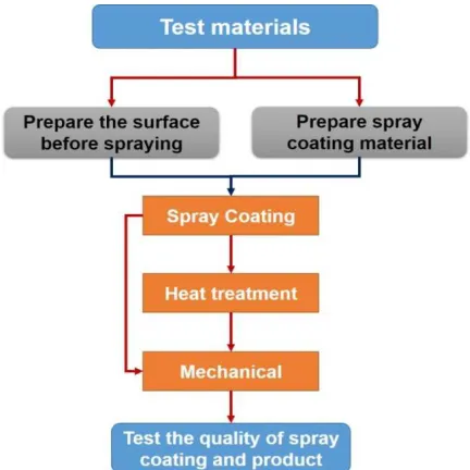
B. Methods
To produce a metal spray, a spraying gun was used. The nozzles of spraying gun were provided with flame gas. Before the TS process, the as-used cylindrical sample was degreased by a lathe to obtain a mean roughness on the surface equal to around 5μm. Spray coating technology can be illustrated in the following Fig. 1.
Fig. 1. Diagram of spray coating technology
rpm, the test time of 600s and rotational diameter of 45 mm. The adhesion values were determined by DLR equipment, and the Vicker hardness was tested by Duramin-Struers.
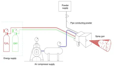
C. Experimental setup
The experimental setup for the TS technology conducted in this study is described in Fig. 2.
Fig. 2. Experimental setup for thermal-spraying technology based on Ni-Cr powder
From Fig. 2, it can be seen the process of spray coating technology based on flame gas including oxygen, acetylene, and compressed air with a pressure of about 5-6 atm. When the oxygen-acetylene mixture was burnt, compressed air was blown up a drop of liquid metal under fine particles with the very high speed of about 100-150 m/s. A spraying distance from the spraying gun to the sample surface was 250 mm. After spraying, coatings were heat-treated with the aim of reducing the density of foam for the increase in the adhesion of sprayed metal with base metal. Metallic coatings were sprayed with diffusion at 1100oC during 8h before carrying out test related to microstructure and mechanical properties. Wear intensity (I) of Ni-Cr thermal spraying layer on the base metal was calculated based on weight method for the test sample, which was built with the dimension shown in Fig. 3, as the following equation:
Fig. 3. The detailed diagram of the sample to wear intensity test
S Q
M I
. ∆
= (1)
I- wear intensity, kg/N.m
ΔM - loss of sample weight after experiment, kg Q - test load, N
S - a running distance of the test sample, m
To test the adhesion of Ni-Cr layer on the surface of CT38 sample after being conducted thermal spraying, a "pulling the latch" method was used and illustrated in Fig. 4.
Fig. 4. "Pulling the latch" method for the adhesion test
Based on Fig. 4, the latch (A) was pulled from the clamping plate (B) by the pulling force (F). The ratio of the maximum pulling force (F) on the clamping surface (S) was considered as the desired adhesion (σk) which was calculated
as followed:
S F k =
III.RESULTS AND DISCUSSION
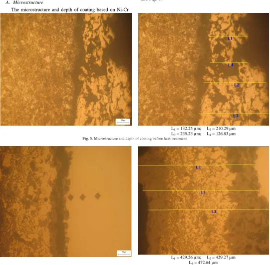
A. Microstructure
The microstructure and depth of coating based on Ni-Cr
and CT38 before and after heat treatment are shown in Fig. 5 and Fig. 6.
L1 = 132.25 µm; L2 = 210.29 µm
L3 = 235.23 µm; L4 = 126.83 µm
Fig. 5. Microstructure and depth of coating before heat treatment
L1 = 429.26 µm; L2 = 429.27 µm
L3 = 472.64 µm
Fig. 6. Microstructure and depth of coating after heat treatment
From Fig. 5, it can be seen that although the spraying process has a high melting temperature, there is no strong association between the base metal and the coating. At the boundary, the microstructure shows that there is only a mechanical adhesion between the coating and the base metal. There is only mechanical adhesion without diffusion between the coating and the base metal so that the hardness value can be high, but the adhesion will be poor. Also, in the microstructure, the presence of porous holes is thought to be caused by the spraying process. The presence of porous holes may reduce the level of bonding of the substrate. However, the coating depth increases after heat treatment,
shows the difference between the spray coating depth and the metal background, the coating thickness increases to about 450μm; meanwhile, the bonding layer thickness is about 25μm. This obtained result shows a diffusion creating a chemical bond between the metal of the layer and the metal background. The formation of this chemical bonding layer increases the adhesion of the coating and metal background, and it is clearly demonstrated in the mechanical tests. When performing heat treatment with diffusive annealing, the bonding phase of the spraying metal and metal background is formed, namely the intermetallic phase of Cr (metal coating) and Fe (the metal background). Furthermore, when processed at high temperature, Ni can be dissolved into the austenite structure of Fe to create an alternative solid solution of Ni-Fe. Because Ni has an atomic size that is different from that of Fe, it changes the size of the lattice and makes up the dislocation of the lattice. As a
result, the durability of the coating increases. Also, there is also a diffusion of C from the metal background based on CT38 steel to the bonding layer and diffusion of the Cr from the bonding layer to the metal background (according to the diffusion principle of the element from the high concentration to the low concentration). Those mentioned above the bi-lateral diffusion is thought to form dispersed carbides in the spray coating aiming to increase the coating's resistance to abrasion. This increase in the depth of coating may be explained by the fact that there is a diffusion that creates a bond between the coating layer and the base metal. After the heat treatment process, a chemical bonding layer is formed between the coating and the base metal. However, the optical imaging also indicates the bond between the coating and the base metal. Based on SEM analysis and mapping shown in Fig. 7, Fig. 8 and Fig. 9, the bond between the base and the base metal has been demonstrated.
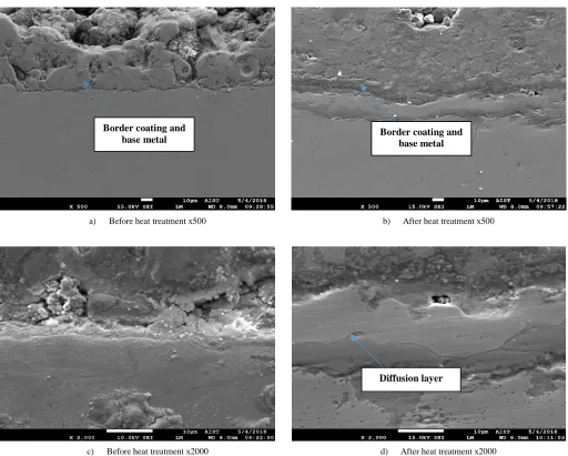
a) Before heat treatment x500 b) After heat treatment x500
c) Before heat treatment x2000 d) After heat treatment x2000
Fig. 7. SEM image of the sample before and after heat treatment
Border coating and
base metal Border coating and base metal
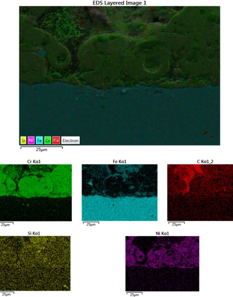
Fig. 9. EDS of the sample after heat treatment
The SEM images presented in Fig. 7a and Fig. 7c before heat treatment show that the samples have a clear separation between the coating and the base metal. This separation results in a peeling effect on the work surface. The SEM analysis shows clearly a bonding layer between the coating and the metal background. Morphological observations also show a clear distribution and formation of a chemical bonding layer after heat treatment. The EDS analysis (Fig. 8) clearly shows the separation between metal background and metal coating. Coating elements all over the coating do not form a diffusion layer between the coating and the base metal. After annealing, the bonding layer in the microstructure (from Fig. 7b and Fig. 7d) is formed between the base metal and the coating. The EDS analysis shows the clarity of this coating layer. The elements are diffused from the coating to the metal. It is this diffusion, which
contributes to the formation of the bonding layer and avoids the peeling during the work of the part. In addition, by mapping analysis, there is diffusion of element Cr from the coating onto the base metal, and carbon from the base metal diffuses to the coating. This creates a bond between the coating and the base metal. These elements can combine to form carbides to increase the wear resistance of the components. The results of the EDS analysis from Fig. 9 show that there are Cr-rich areas, and this is in accordance with the expected results from Fig. 6.
B. Mechanical properties
1) Hardness: Vicker method (HV) is used to measure
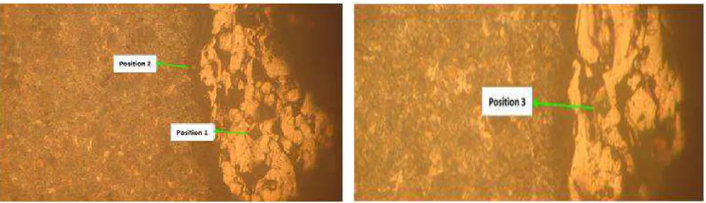
Fig. 10. The hardness value of the sample before heat treatment
Fig. 11. The hardness value of the sample after heat treatment
From Fig. 10, it can be seen that HV of position 1, position 2, and position 3 is respectively 162, 140 and 191. The hardness values odd the above positions of the coating before heat treatment are low. It is because the alloying phases of Fe with Cr and Fe with Ni as well as the carbides of the bonding layer have not been formed yet. However, after heat treatment, the hardness tends to increase. It is seen from Fig. 11 that after heat treatment, hardness values are more evenly distributed than the case of non-heat treatment. The results of HV analysis show that the HV of the coating after heat treatment (302HV) is higher than that before heat treatment (190HV). The results related to the achieved HVs are consistent with the results of microstructure analysis shown in Fig. 6 and Fig. 9. Based on the results of microstructure analysis, there is an appearance of dispersed carbides within the microstructure of the coating and bonding layer, and a high HV may be the result of diffusion.
2) Wear intensity: The wear intensity of the coating on
the metal background after being measured by Eq. (1) is given in Table 3.
TABLEIII THE VALUE OF WEAR INTENSITY
Heat treatment Wear intensity (kg/N.m)
Before heat treatment 5,87.109
After heat treatment 1,89.109
It can be seen from Table 3 that wear intensity of the heat-treated sample is around three times lower than that of the non-heat treated sample. This is explained due to low adhesion between the coating and the metal background before heat treatment resulting in easy removal of the coating from a metal background. Wear intensity results is appropriate to the achieved results of hardness and adhesion. However, heat treatment has created a diffusion of elements from the coating layer into the metal background; as a result, a strong bond formed by the element mentioned above diffusion improves wear intensity.
3) Adhesion The adhesion of the coating on the metal
background after being tested and measured based on Eq. (1) is given in Table 4.
TABLEIV THE RESULT OF ADHESION
Adhesion before heat treatment, MPa
Adhesion after heat treatment, MPa
26.61 28.98
Ni-Cr onto the surface of CT38 (metal background) increases. This result reflects the microstructure of the as-used sample that has been diffas-used to form a complete coating improving the adhesion. Thus, in terms of the mechanical and microstructure aspects, there is a core correlation between microstructure and mechanical properties of the coating before and after heat treatment. Apparently, the heat provides metallic atoms (Ni, Cr, Fe) and the nonmetallic atom (C) with the sufficient energy to overcome the specific linked-energy, and promotes the diffusion bi-laterally aiming at forming new carbide phase or bonding such as CrxCy and Ni-Fe, resulting in a reduction of
the residual stress in the microstructure. The results related to hardness, adhesion, and wear intensity of coating (after being treated by heat) are also similar to published works [21]–[23].
IV.CONCLUSIONS
In this study, the microstructure and mechanical properties of the coating based on 80Ni-20Cr onto the surface CT38 steel in case of heat and non-heat treatment was conducted. The results showed that there was a diffusion of Cr from coating layer into the CT38 background as well as a diffusion of C from the CT38 background into the coating layer to form the new carbide phase and chemical bond between Ni-Fe, these results were demonstrated by SEM and EDS mapping. However, the above-mentioned diffusion was only achieved after heat treatment under 1100oC and during 8h. Regarding mechanical properties of the coating after being treated by heat, the hardness was found with an increase by 60%, wear intensity was 3 times lower, and adhesion was 8.9% higher in comparison with the case of non-heat treatment. The results from this study may be used for the application of the crankshaft repair.
REFERENCES
[1] A. T. Hoang, D. N. Nguyen, and V. V. Pham, “Heat Treatment Furnace For Improving The Weld Mechanical Properties: Design and Fabrication,” Int. J. Mech. Eng. Technol., vol. 9, no. 6, pp. 496–506, 2018.
[2] X. D. Pham, A. T. Hoang, and D. N. Nguyen, “A Study on the Effect of the Change of Tempering Temperature on the Microstructure Transformation of Cu-Ni-Sn Alloy,” Int. J. Mech. Mechatronics Eng., vol. 18, no. 04, pp. 27–34, 2018.
[3] X. D. Pham, A. T. Hoang, D. N. Nguyen, and V. V Le, “Effect of Factors on the Hydrogen Composition in the Carburizing Process,” Int. J. Appl. Eng. Res., vol. 12, no. 19, pp. 8238–8244, 2017. [4] T. N. Le, M. K. Pham, A. T. Hoang, and D. N. Nguyen,
“Microstructures and elements distribution in the transition zone of carbon steel and stainless steel welds,” J. Mech. Eng. Res. Dev., vol. 41, no. 3, pp. 27–31, 2018.
[5] A. T. Hoang, V. V. Le, D. N. Nguyen, and A. X. Nguyen, “A study of the changes in microstructure and mechanical properties of
multi-pass wellding between 316 stainless steel and low carbon steel,” J. Adv. Manuf. Technol., vol. 12, no. 2, pp. 23–35, 2018.
[6] D. N. Nguyen, A. T. Hoang, M. T. Sai, M. Q. Chau, and V. V. Pham, “Effect of Sn component on properties and microstructure Cu-Ni-Sn alloys,” J. Teknol., vol. 80, no. 6, pp. 43–51, 2018.
[7] P. L. Fauchais, J. V. R. Heberlein, and M. I. Boulos, “Overview of Thermal Spray,” in Thermal Spray Fundamentals, Springer, 2014, pp. 17–72.
[8] C. U. Hardwicke and Y.-C. Lau, “Advances in thermal spray coatings for gas turbines and energy generation: a review,” J. Therm. Spray Technol., vol. 22, no. 5, pp. 564–576, 2013.
[9] K. Von Niessen and M. Gindrat, “Plasma spray-PVD: a new thermal spray process to deposit out of the vapor phase,” J. Therm. spray Technol., vol. 20, no. 4, pp. 736–743, 2011.
[10] A. C. Savarimuthu et al., “No Title,” in Proceedings of 1st International Thermal Spray Conference, 2000, p. 1095.
[11] P. L. Ko and M. F. Robertson, “Wear characteristics of electrolytic hard chrome and thermal sprayed WC–10 Co–4 Cr coatings sliding against Al–Ni–bronze in air at 21 C and at− 40 C,” Wear, vol. 252, no. 11–12, pp. 880–893, 2002.
[12] N. Espallargas, J. Berget, J. M. Guilemany, A. V. Benedetti, and P. H. Suegama, “Cr3C2–NiCr and WC–Ni thermal spray coatings as alternatives to hard chromium for erosion–corrosion resistance,” Surf. Coatings Technol., vol. 202, no. 8, pp. 1405–1417, 2008.
[13] A. Ganvir, N. Curry, N. Markocsan, P. Nylén, and F.-L. Toma, “Comparative study of suspension plasma sprayed and suspension high velocity oxy-fuel sprayed YSZ thermal barrier coatings,” Surf. Coatings Technol., vol. 268, pp. 70–76, 2015.
[14] S. Matthews, B. James, and M. Hyland, “High temperature erosion– oxidation of Cr3C2–NiCr thermal spray coatings under simulated turbine conditions,” Corros. Sci., vol. 70, pp. 203–211, 2013. [15] N. Bala, H. Singh, and S. Prakash, “Accelerated hot corrosion studies
of cold spray Ni–50Cr coating on boiler steels,” Mater. Des., vol. 31, no. 1, pp. 244–253, 2010.
[16] Y. Zhang, X. Peng, and F. Wang, “Development and oxidation at 800 C of a novel electrodeposited Ni–Cr nanocomposite film,” Mater. Lett., vol. 58, no. 6, pp. 1134–1138, 2004.
[17] H. Singh, D. Puri, and S. Prakash, “Some studies on hot corrosion performance of plasma sprayed coatings on a Fe-based superalloy,” Surf. coatings Technol., vol. 192, no. 1, pp. 27–38, 2005.
[18] L. Fedrizzi, L. Valentinelli, S. Rossi, and S. Segna, “Tribocorrosion behaviour of HVOF cermet coatings,” Corros. Sci., vol. 49, no. 7, pp. 2781–2799, 2007.
[19] A. Lanzutti, M. Lekka, E. Marin, and L. Fedrizzi, “Tribological Behavior of Thermal Spray Coatings, Deposited by HVOF and APS techniques, and composite electrodeposits Ni/SiC at both room temperature and 300 C,” Tribol. Ind., vol. 35, no. 2, pp. 113–122, 2013.
[20] T. Sundararajan, S. Kuroda, K. Nishida, T. Itagaki, and F. Abe, “Behaviour of Mn and Si in the spray powders during steam oxidation of Ni-Cr thermal spray coatings,” ISIJ Int., vol. 44, no. 1, pp. 139–144, 2004.
[21] A. Sunde, “Properties of thermal sprayed coatings for internal use in pipes and bends.” NTNU, 2015.
[22] M. H. Staia, M. Suarez, D. Chicot, J. Lesage, A. Iost, and E. S. Puchi-Cabrera, “Cr2C3–NiCr VPS thermal spray coatings as candidate for chromium replacement,” Surf. Coatings Technol., vol. 220, pp. 225–231, 2013.