AUTOMATED TELEMETRIC IRRIGATION CONTROLLER By H. D. Fisher,1 A. S. Humphsrys,2 M. ASCE,
and D. A. Young
ABSTRACT: An electronic, microprocessor-based controller was developed and tested for automating surface irrigation systems. Communication between the central controller and individual satellite field stations is by tone telemetry over a single 3-conductor wire. The reliable Dual Tone Multiple Frequency or Touch Tone system is the same as that uses in telephone communications. The system is designed to actuate momentarily energized pilot valves commonly used in automated surface irrigation systems. Because of its low power requirement, the control system can be battery-powered. It is being field tested in three different, auto-mated surface systems.
INTRODUCTION
Automation is being used increasingly to improve farm water applic-ation efficiency. Irrigapplic-ation on lands that are suited for surface irrigation can usually be automated to achieve water and _Leber savings at lower cost and with less energy than is generally required for sprinkler methods of irrigation.
Irrigators have wanted timer-controlled devices and structures for many years to automatically change their irrigation sets, especially at night. An irrigation of less than 12 hours, or between 12 and 24 hours, is often sufficient to refill the soil's root zone. However, irrigators commonly use either 12- or 24-hour sets because it is
con-venient to change the water only once or twice each day. Thus, irrig-ation is scheduled according to the farmer's work schedule rather than by soil and crop conditions. These fixed-time sets are usually satis-factory for sprinkler systems because sprinklers can be designed to apply the desired amount of water in a fixed-time period. Much of the decision making is in the system design rather than with the operator, and when the system is operated according to design, a reasonably ef-ficient irrigation can be expected.. However, with surface irrigation systems, which are used on about two-thirds of the irrigated acreage iu the United States, both the application rate and irrigation timing are controlled by the irrigator. The irrigation system capacity as well as
1
Electronics Engineer, Snake River Conservation Research Center, Kimberly, Idaho.
2
Agricultural Engineer, Snake River Conservation Research Center, Kimberly, Idaho.
3
Research Associate, Colorado State University, Grand Junction, Colorado.
soil and field conditions often limit the irrigator's ability to vary the application rate; whereas, irrigation duration is under his direct control and is usually the most important factor influencing irrigation efficiency. Another factor which increases the need for timer-controlled, automated devices is the cost and limited availability of competent irrigation laborers.
Commercial controllers are designed predominantly for systems which use sprinklers or, more recently, drip equipment and do not
fully meet the needs of surface irrigation. Many of them are designed for relatively short time periods; whereas, automated surface systems may require irrigation sets of 24 hours or longer. Most commercial controllers also require at least one separate connecting wire or tube for communication between the controller and each controlled valve or gate outlet. Thus, the number of wires or tubes that must be handled for most field installations becomes very cumbersome and difficult to manage.
Most controllers require AC line power, but this is seldom avail-able in fields where surface irrigation equipment is used. Also, the controller's electrical output, used to control or actuate solenoid valves, is usually not compatible with the valves used in surface systems. The controllers are designed to operate continuously-energized solenoid valves while most automated surface systems use !.:'momentarily-energized pilot valves which can be powered by batteries.
Continuously-energized solenoid valves commonly used in pressurized irrigation systems require pressure for sealing and/or shifting. Since they are pressure-assisted, their wattage requirement is often smaller than that required by some momentarily-energized solenoid valves (8) powered by capacitor discharge. Latching solenoid valves used in some surface systems require a reversed polarity voltage not obtainable from controllers designed for continuously-energized soleniod valves. Therefore, controllers are needed which have an output that is compatible with solenoid pilot valves used in surface irrigation systems.
A number of electronic timers or controllers have been used on an experimental basis. Edling at al. (3) described a solid state timer to control a single, pneumatically-actuated irrigation turnout valve. Duke et al. (2) and Dedrick and Allen (1) used an electronic controller to provide volumetric control of an automated farm irrigation system with water supplied from open cnannels. Fisher et al. (5) used electronic controllers both for single station, automatic furrow cutback systems and as central controllers. Menges et al. (9) used a radio-operated controller for a gated pipe system.
Since a controller compatible for use with momentarily-energized valves in a surface irrigation system was not commercially available, we designed and tested a controller to satisfy this need. The objec-tive of this paper is to describe a control system which uses tone telemetry and a single, 3-conductor control wire for communication between the controller and all controlled stations in the irrigation system. The system's operation and field tests are also described.
ELECTRONIC CONTROLLERS
252 ADVANCES IN IRRIGATION AND DRAINAGE AUTOMATIC IRRIGATION CONTROLLER 253
Their low power requirement enchances the feasibility of using solar and wind energy sources as well as batteries for power. Their time base is a quartz crystal oscillator which provides a high degree of
timing accuracy. This is necessary where gates or valves'are control-led by individual controllers and are operated in sequence. Cumulative errors with inaccurate timers could result in overtopping of ditches or canals or damage to the system by having all system outlets closed simultaneously. Controllers using microprocessors can be programmed to control irrigation in any sequence from a large number of turnouts and for varying time intervals. The basic components are relatively inexpensive and once the design and circuit 'boards are developed for a given unit, they can be economically produced in quantity. Complete system control incorporating soil and crop conditions, weather para-meters, water supply limitations, and irrigation scheduling consider-ations is feasible.
TONE TELEMETRY CONTROLLER
The design of this system is such that the timing, programming and control functions are concentrated into one versatile central controller. The satellite station controllers contain only the cir-cuitry necessary to decode commands from the central controller and to actuate the valves. This design allows the central controller to be quite sophisticated, since only one is needed for a given instal-lation, while the number of individual stations can be expanded easily and at nominal cost.
Three wires connect the station controllers and the central controller daisy-chain fashion. Two wires carry power to the station controllers, while the third carries the on-off commands from the central controller. The distance that any station can be from the central controller is limited by the voltage drop along the power supply wires. Heavier wire can be used to increase the effective distance, but this increases the installation cost. Radio links to the stations would remove this limitation, but would increase the cost of the station controllers..
Central Controller
The central controller is based on an 1802 microprocessor. A Read Only Memory (ROM) contains the main program so that field program-ming is not necessary to activate the system. The operator enters control information which determines how the system will operate for a given irrigation cycle. These parameters are stored in Random Access Memory (RAM) and can be easily adjusted at random and at any time. The controller communicates with the controlled field stations using the full 4 x 4 matrix of telephone Dual Tone Multiple Frequency (DTMF or Touch Tone)— These represent the hexadecimal digits O F (0 - 15 decimal). This system uses two-digit station addresses 01 - FE (00 and FF are stable states). Commands 01'- 7F (hex) open valves 1 - 127 (dec), while the l's complements FE - 80 (hex) close
them. The DTMF system was developed for telephone communication and is 4/ Touch Tone is a registered trademark of American Telephone
and Telegraph.
very dependable. The chance of a malfunction resulting from lighting or other electrical disturbances is remote since the system is resist-ant to interfenence by noise from outside sources. Earlier models of the controller were designed to operate from a 12 VDC power source. The latest model, however, was designed to operate from 120 VAC to simplify supplying the short-term voltage required by station control-lers a long distance away from the central station.
To obtain reliable operation of momentarily-energized, 3- and 4-way pilot valves at the end of 1300 ft (400 m) of 18 AWG wire, the short-term voltage at the central controller had to be in the range of 32 - 36 VDC. The actual power demand of the system is quite low, 6 ma at 5 VDC, when the station controllers are powered down, and 600 ma at 32 VDC for about 45 seconds when 16 stations are controlled. A storage battery and a DC to AC inverter can supply this demand at a location where line power is not available. Part of the power requirement at the central controller is used to charge capacitors in the individual station controllers. Power at the controller can be reduced by using batteries at the field station controllers to charge the capacitors. Thus, a completely battery-powered system is feasible.
Station Controllers
Each station controller is assigned an address 1 - 127 (dec) when
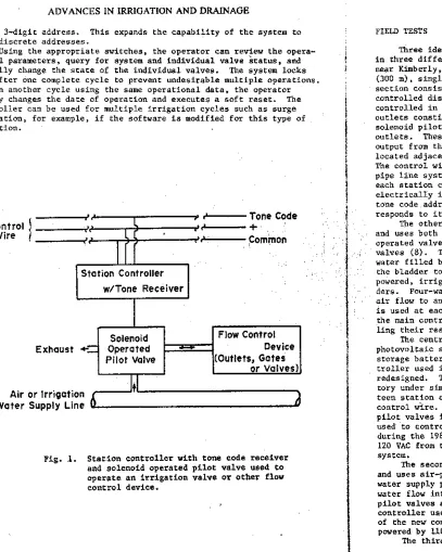
the system is designed. The single chip DTMF tone receiver at each station decodes commands from the central controller and the decoded commands are compared to the address set in the station controller. If the command is valid, the station controller generates the appro-priate signal to shift the valve. The output structure and solenoid drivers can be readily modified to accommodate most momentarily-energized, bistable valves for air or water. Two types of solenoid-operated pilot valves are being controlled by the station controllers now in use. One is a magnetically-latched solenoid valve which re-quires a reversed polarity electrical output from the station control ler to open and close the valve. Three-way pilot valves of this type are commonly used with pneumatically-operated irrigation valves (2, 3, 4, 6). The other pilot valves are 3- and 4-way momentarily-energized spool valves used with both water and air operated irrigation valves (7, 8). The pilot valves are powered by the electrical discharge from capacitors in the station controllers. The capacitors are charged from the central controller. A schematic representation of a station controller and its associated pilot valve is shown in Fig, 1,
Operation
The operator supplies the operational parameters: (a) present date and time, (b) date system is to operate, (c) time of operation, and (d) duration of irrigation for each station. By selecting a
Tone Code es
e Common
Control Wire
Station Controller w/Tone Receiver
Exhaust .4C:
Solenoid Operated Pilot Valve
Flow Control Device (Outlets, Gates
or Valves)
Air or Irrigation Water Supply Line
use a 3-digit address. This expands the capability of the system to 2047 discrete addresses.
Using the appropriate switches, the operator can review the opera-tional parameters, query for system and individual valve status, and manually change the state of the individual valves. The system locks out after one complete cycle to prevent undesirable multiple operations. To run another cycle using the same operational data, the operator merely changes the date of operation and executes a soft reset. The
controller can be used for multiple irrigation cycles such as surge irrigation, for example, if the software is modified for this type of operation.
Fig. 1. Station controller with tone code receiver
and solenoid operated pilot valve used to operate an irrigation valve or other flow
control device.
FIELD TESTS
Three identical central controllers were made for field testing in three different automated irrigation systems. The first system near Kimberly, Idaho, consists of two parts, one of which is a 900-ft
(300 m), single-pipe system with pneumatically-operated outlets. This section consists of a conveyance/distribution pipe with automatically-controlled discharge outlets for individual furrows. The outlets are controlled in groups or banks of 15 to 25 outlets each. Each group of outlets constitutes one field station. A 3-way, magnetically latched, solenoid pilot valve controls air flow to and from each group of outlets. These pilot valves require a reversed polarity electrical output from the station controller. A telemetry station controller is located adjacent to the pilot valve for each controlled bank of outlets. The control wire from the central controller extends the length of the pipe line system as shown schematically in Fig. 2, and is connected to each station controller such that all field stations are connected electrically in parallel. Each station controller sees all of the tone code addresses transmitted by the central controller, but only responds to its own address.
The other part of the automated system is in an adjacent field and uses both and air-operated irrigation valves. The water-operated valves use 3-way, momentarily-energized spool type pilot valves (8). These pilot valves direct water from the pipe line into a water filled bladder inside the irrigation valve or drain water from
the bladder to either close or open the irrigation valve. The air-powered, irrigation valves are butterfly valves actuated by air cylin-ders. Four-way momentarily-energized solenoid spool valves (7) control air flow to and from the air cylinders. A telemetry station controller is used at each valve station. These units receive instructions from the main controller and open or close the irrigation valves by control-ling their respective pilot valves.
The central controller for the Kimberly system is powered by a photovoltaic solar cell battery charger, Fig. 2, and two 12-volt storage batteries. Since the power requirement for the original con-troller used in this field was relatively high, the concon-troller was redesigned. Three new controllers were built and tested in the labora-tory under simulated field conditions. The simulation included four-teen station controllers located at the far end of a 1300-ft (400 m) control wire. These were repeatedly operated with their associated pilot valves in a random sequence. One of the new controllers will be used to control approximately 25 valve stations in the Kimberly system during the 1983 irrigation season. An inverter will be used to provide 120 VAC from the solar charged batteries to power the controller
system.
The second irrigation system is in the Grand Valley of Colorado and uses air-powered butterfly valves attached to risers from a buried water supply pipeline. The 14 irrigation valves in this system control water flow into gated pipe. Four-way, momentarily-energized solenoid pilot valves are used with the butterfly valves (7). The early-model controller used during 1982, was underpowered and was replaced by one of the new controllers for the 1983 season. The controller will be powered by 110 VAC line power which is available near the field.
I:o a P. P-1 4-1
0. I. of
0 110 0 C
a a
I -w
a
•
cV
256 ADVANCES IN IRRIGATION AND DRAINAGE AUTOMATIC IRRIGATION CONTROLLER 257
water-operated valves and the same 3-way, momentarily-energized pilot valves noted earlier. The controller for this system is identical to chose for the other two systems and is powered directly from 110 VAC. Field tests conducted with the first models of the controller showed that the basic design and principles of operation were sound. Debugging of program and power requirement problems were solved such that the new controllers, which include updated components, performed satis-factorily in simulated field tests conducted in the laboratory.
SUMMARY
An electronic microprocessor-based controller was developed for automating surface irrigation systems. The control system consists of a central controller containing the timing, programming and control functions and individual satellite station controllers at each field station. Communication between the central controller and the satellite stations is by tone telemetry over a single 3-conductor wire. This eliminates multiple wires or tubes between the central controller and field stations which are common with conventional controllers. The Dual Tone Multiple Frequency (DTMF or Touch Tone) system is the same as that used in telephone communication and is very reliable. Each station controller contains a tone code receiver/decoder which responds to its own address. The output of each station controller is designed to operate battery-powered, magnetically-latched, poppet and momentarily-energized spool type solenoid pilot valves that are commonly used in automated surface irrigation systems. Early models of the central controller where field tested in three different irrigation systems. Three controllers of an updated design were tested under simulated fiels conditions in the laboratory and will be used in the three field systems during 1983. The controller system has a relatively low power requirement.
APPENDIX - REFERENCE
1. Dedrick and R. F. Allen. 1981. Open channel flow sensing for auto-matic control. ASAE Paper No. 81-2562, ASAE, St. Joseph, MI. 49085.
2. Duke, H. R., M. L. Payne and D. C. Kincaid. 1978. Volumetric control for irrigation automation. ASAE Paper No. 78-2545, ASAE, St. Joseph, MI. 49085.
3. Edling, R. J., H. R. Duke and M. L. Payne. 1978. Utilization of a portable solid state furrow irrigation valve controller. ASAE Paper No. 78-2546, ASAE, St. Joseph, MI. 49085.
4. Fischbach, P. E. and R. Coodding II. 1971. An automated surface irrigation valve. Agr. Eng. 52(11):584-85.
5. Fisher, H. D., A. S. Humpherys and R. V. Worsteli. 1978.
6. liaise, H. R., E. G. Kruse, M. L. Payne and H. R. Duke. 1980. Automation of surface irrigation: Summary of 15 years USDA Research and Development at Fort Collins, Co. U. S. Department. ,of
Agriculture, Production Research Report No. 179, 60 p.
7. Humpherys, A. S. 1983. Automated air-powered irrigation butterfly valves. Accepted for publication in Trans. ASAE.
8. Humpherys, A. S. and R. S. Pauliukonis. 1983. Momentarily-energized pilot valves for irrigation systems. Accepted for publication in Trans. ASAE.