Volume 2, Issue 10, October 2013
Page 113
ABSTRACT
Fiber optical parametric amplifiers (FOPAs) based on four-wave mixing occurring inside optical fibers, can provide a large and flat gain over a wide bandwidth when designed suitably. In this paper, the coupled propagation equat ions of the dual-pumps FOPA were solved analytically by considering the fiber as a concatenation sections, each one with very small length. A novel recursive relation of the resulted signal and idler waves was found. This relation may be determined the FOPA gain as a function to the input signal. Thereafter, the phase mismatch condition are analyzed in order to maximize the FOPA characteristics. An accuracy of the present solution coincides the numerical one and gives an excellent results within a few number of iterations. It was found that the center of FOPA with respect to zero wavelength is very important property to enhance the FOPA gain. However, the parameters of chromatic dispersion and the location of amplifier center are analyzed in order to calibrate the dual-pumps FOPA.
keywords: FOPA, FWM, phase matching condition.
1. INTRODUCTION
In addition to provide broadband and high gain, fiber optical parametric amplifiers (FOPAs) are spectrally flexible, they can operate with low noise features and they offer the possibility to achieve simultaneously wavelength conversion. Indeed, it has been experimentally demonstrated that they can exhibit a gain bandwidth of more than 200 nm [1], a net black-box gain up to 49 dB and a conversion efficiency of 38 dB [2]. Moreover, it has been also shown that FOPAs can directly generate a broad and flat gain region by using two pump lasers [3] or multiple fibers with different group-velocity dispersions [4]. The latter case has been recently checked against experimental measurements that demonstrate a flattened gain bandwidth of 75 nm in a two fiber FOPA scheme [5]. However, a major limitation of FOPA performances lies in the high pumping level. In response to this limitation, highly nonlinear fibers that have a large nonlinear coefficient [1], [2], [6] have been proved to be the best candidates for FOPA.
For future broadband wavelength division multiplexing (WDM) requires amplifiers to compensate the loss of fiber and equalize the power of the various channels, the semiconductor optical amplifier (SOA), the erbium doped fiber amplifier (EDFA), and Raman amplifier (RA) have been applied widely to provide a flat gain spectrum. But low loss windows (1250-1650 nm) of all-wave fiber can’t be utilized fully, therefore it is very important to seek a new optical amplifiers operating outside of SOA, EDFA and RA gain bandwidth, and then a new type of broadband amplifier, FOPA is put forward, which utilizes four wave mixing (FWM) to amplify the signals and offers a broadband amplification at arbitrary wavelengths [7]-[12]. Furthermore, FOPA can also provide small noise penalties that are lower than the 3-dB quantum limit and is used as broadband wavelength converters, return to zero pulse generation, and all-optical sampling,.. etc [13]. Though simple single-pump FOPA could offer a gain bandwidth of more than 200 nm, the gain spectrum is not flat over the amplifier bandwidth but has a difference as high as 15 dB between the lowest and the highest value [14], which brings to the difficulty to equalize the power of the various channels in WDM systems. For this reason, much research has been done recently to deal with the lack of flatness of the gain spectrum for pump FOPA [15], [16]. However, single-pump FOPA has several inherent problems. On the one hand, the single-pump frequency overlaps the signal band, which makes it difficult to filter out the pump. On the other hand, when single-pump FOPA is operated in CW mode, the idler spectrum is broadened due to the required pump dithering, which degrades the bit error rate (BER) when FOPA is used as wavelength converter. Therefore dual-pump FOPA is introduced [17], [18], which results in at least three distinct parametric processes that can be balanced to create a broad and flat CW gain spectrum by suitable use of dispersion, unattainable by a single-pump FOPA [19].
In this paper, the FOPA with the case dual pumps is analyzed. Thereafter, the coupled propagation equations are solved analytically under a certain approximations that consider the pumps power much more than the signal and idler powers. This approximation is very sensitive in order to neglect the pumps depletion. As a consequence, the coupled propagation equation are solved in analytic manner over a small distance of fiber. This solution are then generalized to include the total fiber length. Also, the phase matching condition is interpreted under the effects of the wavelength difference between the pumps and the amplifier center with respect to zero dispersion wavelength.
Theoretical Calibration of Dual-Pumps Fiber
Optical Parametric Amplifier
Muayad H. Salman1, Ali H. Hassan2, and Hassan A. Yasser3
1
Physics Department, College of Education, Mustansiriyah University
Volume 2, Issue 10, October 2013
Page 114
2. STATEMENT OF THE PROBLEM
We consider an electric field consisting of four continuous waves (CWs), at frequencies w1 through w4. In NFWM, the four distinct waves interact with each other under the condition w1w4 w2w3. Two of these, number 1 and 2, are in this work used as pumps, while 3 is a signal, also denoted s, that is to be amplified, and 4 is the idler, i, that arises when the signal is amplified. Under the assumption that the four waves are sufficiently separated in frequency and the input fields are parallel polarized, the nonlinear Schrödinger equation (NLSE) can be reduced to four coupled differential equations for the complex field amplitudes [20], [21]
] | | 2 | [| 2 * 4 , 1 2 2
m z i n m j j j k k k j j j jj A i A A A i A A A
e
mndz dA (1)
Where j1,2,3,4, mnmnnn, j are the nonlinearity factors, jare the wavenumbers, and j are the
attenuation factors. Note that; the last term represents all combinations that satisfy the condition mnj0. To solve Equation.(1) analytically, many assumptions must be done, which are: the attenuation factors are assumed to be equal, the nonlinearity factors also may be assumed a same, and the pump powers remain much larger than the signal and idler powers at all times and that the power losses of the pumps is negligible. Under these assumptions, Equation.(1) may be obtained
| | | |
(5) 2 2 (4) | | | | 2 2 (3) | | 2 | | 2 ) 2 ( | | 2 | | 2 * 3 2 1 4 2 2 2 1 4 4 * 4 2 1 3 2 2 2 1 3 3 2 2 1 2 2 2 2 1 2 2 2 1 1 1 z i z ie
e
A A A i A A A i A dz dA A A A i A A A i A dz dA A A A i A dz dA A A A i A dz dA 3. THEORETICAL MANAGEMENTS
The later set of equations completely determines the propagation dynamics of the optical signals along the fiber with loss and without pump depletion. Using the powers definitionPj Aj 2, one may be obtained
2
e 2 z -j k j j j A P P i A dz dA (6)
where k2,1 if j2,1. Using the transformations - z/2
e
j j B
A into the last equation will get
e ] 2
[ -z
j k j j B P P i dz dB
(7)
It is a straightforward to solve Equation. (7) to obtain Bj(z)Bj(0)exp[i(Pj 2Pk)zeff], where (1-e )/
z - eff z is
the effective length of the fiber. The amplitudes Bj may be returned toAj
yield ( ) (0) /2exp[ ( j 2 k) eff]
z j
j z A e i P P z
A . Using these results into Eqs.(4) and (5), yields
e 2 e ) ( 2 2 4 ) ( 3 z -2 1 z -2
1 1 2
A i P P A i PP e A
dz dA eff Z P P i z i j j
j
e
(8)Herek=4, 3 if j=3,4. Now, using the transformations
] e ) ( 2 -z 2
[-exp 1 2 -z
i P P
B
Aj j (9) into Equation. (8) and simplifying the result, we get
e
2 1 2 - z
iKz k
j DB P P i dz dB
e
(10)
where
K
(P1P2)LNL is the total phase mismatch, and Dexp[4i(P1P2)/]. Using Equation. (10)and its complex conjugates, we get the second order generalized equation
0 e
4 1 2 -2 z
2
HZ PP Z
Z (11) Where H iK for the cases
B3,B4
Z . The latter two equations can't be solved analytically except for the case
1
e-2z and this approximation is satisfied for small length, i.e. z.
Volume 2, Issue 10, October 2013
Page 115
(12b) e e (z) (12a) e e (z) z 4 z 3 4 z 2 z 1 3 * 2 * 1 2 1 m m m m C C B C C BWhere ( ) g, 2
1
1 iK
m ( ) g ,
2 1
2 iK
m 1 2
2 2 16 ) ( 2 1 P P iK
g .
Note that; C's are constants that must be determined and
g
represents the gain parameter. To determine the constants C's, the initial conditions are applied at z0 to get(0) ) 0 ( z) ( z) ( 4 3 4 3 B B a b b a B B (13)
At this point we get a complete solution for one section with z length. Equation. (13) can be written in general form as
) 14 ( ) ( ) ( ) ( ) ( ) ) 1 (( ) ) 1 (( 4 3 4 3 4 3 z m B z m B a b b a z m B z m B T z m B z m B m
Here, the matrix Tm represents the transfer matrix of the mth section, which in fact does not depend on the section index. Their elements are defined as
) sinh( 2 ) ( ) cosh( e 2 ) ( g z g iK z g a z iK ) sinh( 2
e 2 1 2
) ( g z g P P D i b z iK
The conversion of the amplitudes
B
j toA
j, will obtain the recursive formulaz) ( z) ( z) ) 1 (( z) ) 1 (( 4 3 * * 2 / 4 3 m A m A u v v u e m A m A z
(15)
where m0,1,..N1, and
) ( ) ( 2 3 e ) sinh( 2 e ] ) sinh( 2 ) ( ) [cosh( 2 1 2 1 z ) ( 2 1 z
4
2m
y
x
P P P P g z g P P D i v g z g iK z g u y x i ix
Equation (15) represents the most important achievement in this paper as it illustrates an analytical solution of the 2-P FOPA in presence of attenuation. The conversion efficiency of any FOPA is the ratio of the output power of the conjugated signal and the input signal power, i.e. for the FWM-based FOPA it is given byG4(L)P4(L)/P3(0). Also, the input signal exhibits
amplification (or attenuation) due to the FWM process. The signal gain is defined as the output signal power to the input signal power, i.e. G3(L)P3(L)/P3(0). In particular, when there is no idler field at the input of the fiber, the signal gain
becomes ) ( sinh 4g ) ( ) ( cosh | | ) ( 2 2 2 2 2 3
e s e gL iK gL
L
G L L (16a)
) ( sinh 4 | | )
( 21 2 2
2 2 4
gL
g P P e r e L
G L L (16b)
The above equations show that, to achieve flat and broadband gain, two conditions must be met. Firstly, K should be near some constant with low ripple over large-signal wavelength range, that means K/(ws) must be small. Secondly, absolute value of this constant should be as small as possible, otherwise the gain may be too low to be practical. In a word,
Volume 2, Issue 10, October 2013
Page 116
4. PHASE MATCHING CONDITION
The signal and idler gain spectra are symmetric with respect to the center frequency. It is convenient to usewc and wd
as the two independent parameters, instead of w1 and w2, and to get maximum parametric gain in Equation. (16a), the total phase mismatch K should be equal to zero or when (P1P2) , and this occurs at signal frequencies that satisfy the well-known phase matching condition, [22]
0 ) ( 1 2
P P (17) and the linear phase mismatch is given by [23]
] ) ( ) [( 12 ] ) ( )
[( 2 2 4 4 4
2
2
1 p s d s d
p i
s w w w w
(18)
4 0 4
2 0 3
2 (wcw ) ( 2)(wcw )
(19)
where
2 1,
, ,ip p s
are the signal, idler, pump one and pump two propagation constants, respectively, wc(w1w2) 2, c
c d
c
s w w w w w w w w w
w
3 , ( 1 2) 2 1 2 . Equation. (18) may be
(20) ) ) ) ) 2 ( (
2 (
) (( 6 R ) ) ) 2 ( (
2 (
) ) )(( ) ( R ) ( R ( )
( 4
2 2 4
3 3 2
2 2 2 2
3 3 2
0 2 0 1
B B B
B
C c
c
C c
c
c c
c c c
where 4
4 2 3 3
1 (2 ) , R ( /2)(2 )
R c c , cc0, 10B/2, 20B/2,B21 is the bandwidth, and
2is the second-order dispersion, and
3,
4are the third- and forth-order dispersions respectively, generally provided by manufacturers, w0 is the zero-dispersion wavelength ZDWL.Therefore, adjusting separately each the pump central wavelength, ZDWL and two pump wavelengths, the magnitude and shape of the gain spectrum can be optimized. The
B
term contributes only when two pumps are used and is independent of the signal and idler frequencies. This difference provides the main advantage of 2-P FOPA over 1-P FOPA as theB
term can be used to control the phase mismatch.By properly choosing the pump wavelengths, it is possible to use this term for compensating the nonlinear phase mismatch (P1P2)stemming from SPM and XPM. As a result, the total phase mismatch K can be maintained close to zero over a quite wide spectral range after the first term is made small by balancing carefully different orders of fiber dispersion. The importance of the
B
term can be best seen by comparing the phase-matching parameter K for 1- and 2-P FOPA. Equation. (3.79) shows that it is hard to maintain this phase-matching condition over a wide bandwidth in a 1-P FOPA. This is because0when the signal wavelength approaches the pump wavelength, and henceK(P1P2) .The net result is that the signal gain is considerably reduced in the vicinity of the pump wavelength, and the gain spectrum exhibits a dip when 1-P FOPA is used. However, in the case of 2-P FOPA, by choosing the pump frequencies properly, Bcan be used to compensate for nonlinear contribution to phase mismatch.
5. RESULTS AND DISCUSSION
In what follows, we will demonstrate how can get high, flat, broadband gain spectrum for any realistic set of experimental FOPA parameters. Our simulation of the transmission is characterized by a large number of different parameters, most of which do not change from simulation to another. For completeness, we list a typical parameters set below, and maintain deviations from these values whenever they occur except when refer to that. We set 10 1 km
W
, P1P21.2W, which could be easily achieved with a CW pump in a highly nonlinear fiber, L0.2km, the fourth-order dispersion
km s 10 × 1
= -52 4
4
, the third-order dispersion =0.1×10-36 s3 km
3
, attenuation coefficient -1
0.046Km
, and
N L z
N20 , , ZDWL 01550nm and in all the following figures, we have constrained 2to value given by
Equation. (19) for parameters used.
Figure (1) represent a compare between the suggested model and numerical solution of the gain spectrum for 2-P FOPA at many values of bandwidthB andfrequency detuningcc0, each shape represent the gain spectrum at fixed parameters, it is evident that the best gain has been terminated by fixing c0 shifting. Whereas the reiteration number
Volume 2, Issue 10, October 2013
Page 117
Figure(1): The gain spectrum of 2P- FOPA for differentB, where each curverepresents the optimum gain by selecting the requiredc0.
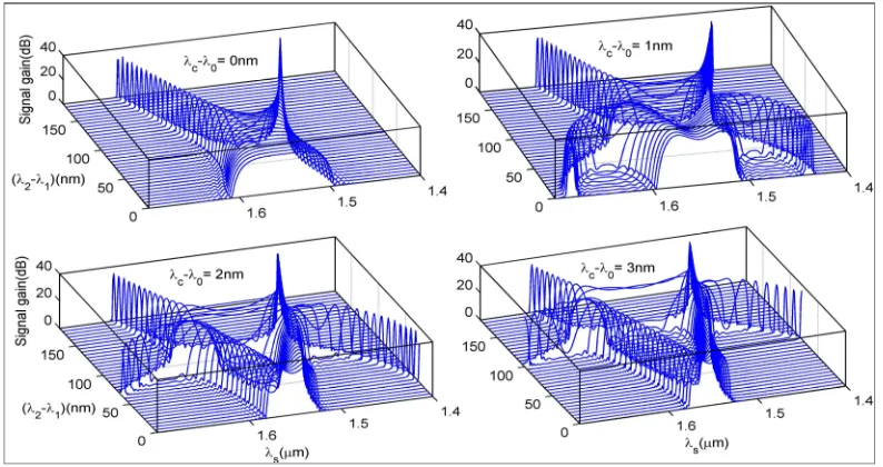
Figure (2) represents the gain spectrum resulting for 2P-FOPA by the adoption of several values to the amplifier center shiftingc0 and each shape has the range of bandwidthB between0180nm. Since, it is evident from the figure the
fact that c00 can not achieve broad bandwidth for all values of B as long as the optimum gain does not happen at
thec00. With broadeningc0 value we notice possibility to achieving broad gain at certain values of bandwidth B. Accordingly, we expect a balance between Band c0 to achieve the ideal gain and that is what will explain in the
following figures.
Figure(2): The gain spectrum of 2P-FOPA as a function of B andc0
Figures (3), and (4) represent the relationship between Band c0 for several values of3and4. The two figures represent a very accurate normalization for amplifier operation. In Figure (3) evident that, at constant4with varying3, this will increase or decrease the range of c0 for the same value ofB. This change, which caused by3, increases
with increasing4. In general, at all4 values, there is a value forc0 that corresponding certainB, at this value, no change will be occurs because of 3 changes. Either in Figure (4), varying 4with proven 3also will increase or reduce the range of c0 for the same value ofB, and there is a value for c0 corresponding certain B does not
Volume 2, Issue 10, October 2013
Page 118
of c0 and that lead to reduce the flatness value of the spectrum and vice versa for Figure (4). In general, to getting larger bandwidth it is better to use fixed value of 4against varying in4value, while, to get the best flatness it is better to use a stability value of3 against varying 4value. Balancing between3and4, makes the possibility of obtaining the optimum spectrum less difficult.
Figure(3): B as function of c0for different values of 3and 4.
Figure(4): B as function of c0for different values of 3and 4.
6. CONCLUSIONS
For small bandwidth B, the optimum gain happens at small c0 values, but for highB, the optimum solution will be
at high c0 values. The flatness ratedecreases by increasing bandwidth and vice versa. The balancing between Band
0
c may be achieved the ideal gain. To get larger bandwidth, it is better to use fixed value of4against varying in3
Volume 2, Issue 10, October 2013
Page 119
REFERENCES
[1] M. E. Marhic et al., “Broadband fiber-optical parametric amplifiers,” Opt. Lett. 21, 573 (1996).
[2] M. C. Ho et al., “200-nm-bandwidth fiber optical amplifier combining parametric and raman gain,”J. Lightwave Technol. 19, 977 (2001).
[3] J. Hansryd and P. A. Anderkson, “Broadband continuous-wave-pumped fiber optical parametric amplifier with 49 dB gain and wavelength conversion efficiency,” IEEE Photon. Technol. Lett. 13, 194 (2001).
[4] M. E. Marhic et al., “Broadband fiber-optical parametric amplifiers and wavelength converters with low-ripple Chebyshev gain spectra,” Opt. Lett. 21, 1354 (1996).
[5] L. Provino et al., "Broadband and nearly flat parametric gain in single-mode fibers,” In Conference on Lasers and Electro-Optics’2000, Conference digest, p. 81, paper Ctul2 (September 10-15, 2000, Nice, France).
[6] S. E. French and J. L. Blows, “Continuous wave optical fibre parametric amplifier with flattened gain,” Optical Amplifiers and Their Applications, (Optical Society of America, Washington DC, 2001), paper PD7 (July 1-3, Stresa, Italy).
[7] M. E. Marhic et al., “High-nonlinearity fiber optical parametric amplifier with periodic dispersion compensation,” J. Lightwave Technol., 17, 210 (1999).
[8] Roger H. Stolen and John E. Bjorkholm, “Parametric Amplification and Frequency Conversion in Optical Fibers,” IEEE J. Quantum Electron. QE-18, 1062-1071 (1982).
[9] F. Yaman, Q. Lin, S. Radic, and Govind P. Agrawal, “Impact of Dispersion Fluctuation on Dual-Pump Fiber-Optic Parametric Amplifiers,” IEEE Photon. Technol. Lett. 16, 1292-1294 (2004).
[10]Per Kylemark, Per Olof Hedekvist, Henrik Sunnerud, Magnus Karlsson and Peter A. Andrekson, “Noise Characteristics of Fiber Optical Parametric Amplifiers,” IEEE J. Lightwave Technol. 22, 409-416 (2004).
[11]A. Mussot, A. Durécu-Legrand, E. Lantz, C. Simonneau, D. Bayart, H. Maillotte, and T. Sylvestre, “Impact of pump phase modulation on the gain of fiber optical parametric amplifier,” IEEE Photon. Technol. Lett. 16, 1289-1291 (2004).
[12]F. A. Callegari, J. M. Chavez Boggio, and H.L. Fragnito, “Spurious four-wave mixing in two-pump fiberoptic parametric amplifiers,” IEEE Photon. Technol. Lett. 16, 434-436 (2004).
[13]Jaeyoun Kim, Özdal Boyraz, Jin H. Lim, and Mohammed N. Islam, “Gain Enhancement in cascaded fiber parametric amplifier with quasi-phase matching: theory and experiment,” IEEE J. Lightwave Technol. 19, 247-251 (2001).
[14]Jonas Hansryd, Peter A. Andrekson, Mathias Westlund, Jie Li, and Per-Olof Hedekvist, “Fiber-Based Optical Parametric Amplifiers and Their Applications,” IEEE J. Sel. Top. Quantum Electron. 8, 506-520 (2002).
[15]Min-Chen Ho, Katsumi Uesaka, Michel Marhic, Youichi Akasaka and Leonid G. Kazovsky, “200-nm- Bandwidth Fiber Optical Amplifier Combining Parametric and Raman Gain,” IEEE J. Lightwave Technol. 19, 977-980 (2001).
[16]L. Provino, A. Mussot, E. Lantz, T. Sylvestre, and H. Maillotte, “Broadband and flat parametric amplifiers using a multi-section dispersion-tailored nonlinear fiber arrangement,” J. Opt. Soc. Am. B 20, 1532-1537 (2003).
[17]Wen Zhang, Chengao Wang, Jianwei Su, Chun Jiang and Weisheng Hu, “ Design of fiber optical parametric amplifier,” IEEE Photon. Technol. Lett. 16, 1652-1654 (2004).
[18]C. J. Mckinstric, S. Radic and A. R. Chraplyvy, “Parametric Amplifier Driven by Two Pump Waves,” IEEE J. Sel. Top. Quantum Electron. 8, 538-547 (2002).
[19]S. Radic and C. J. Mckinstric, “Two-pump fiber parametric amplifiers,” Opt. Fiber. Technol. 9, 7-23 (2003).
[20]J. Hansryd, P. A. Andrekson,M.Westlund, J. Li, and P. O. Hedekvist, “Fiber-based optical parametric amplifiers and their applications,” Selected Topics in Quantum Electronics, IEEE Journal of, vol. 8, pp. 506–520, May 2002.
[21]M. Marhic, "Fiber Optical Parametric Amplifiers, Oscillators and Related Devices". Cambridge: Cambridge University Press, 2007.
[22]R.H. Stolen and J.E. Bjorkholm, ”Parametric Amplification and Frequency-Conversion in Optical Fibers,” IEEE J. Quantum Electron. 18 1062-1072 (1982).]