A FAST METHOD FOR CALCULATION OF
TRANSFORMERS LEAKAGE REACTANCE
USING ENERGY TECHNIQUE
A. Naderian Jahromi, Jawad Faiz and Hossein Mohseni
Department of Electrical and Computer Engineering Center of Excellence in Applied Electromagnetics
Faculty of Engineering, University of Tehran, P. O. Box 74395/515 Tehran, Iran, [email protected]
(Received: June 23, 2002 – Accepted: February 6, 2003)
Abstract Energy technique procedure for computing the leakage reactance in transformers is
presented. This method is very efficient compared with the use of flux element and image technique and is also remarkably accurate. Examples of calculated leakage inductances and the short circuit impedance are given for illustration. For validation, the results are compared with the results obtained using practical tests for 3 types of a small single-phase transformer, 3-phase distribution transformers and a high voltage test transformer were studied.
Key Words Leakage Reactance, Transformer, Electromagnetic Energy, Inductance
ﻩﺪﻴﻜﭼ
ﻩﺎﺗﻮﻛﻝﺎﺼﺗﺍﺲﻧﺍﺪﭙﻣﺍ ،
ﺮﺘﻣﺍﺭﺎﭘﻚﻳ
ﺭﺩﻢﻬﻣ ﻱﺭﺍﺩﺮﺑﻩﺮﻬﺑﻭﻲﺣﺍﺮﻃ ﺯﺍ
ﺭﻮﺗﺎﻣﺭﻮﻔﺴﻧﺍﺮﺗ ﺖﺳﺍ
. ﻪﻟﺎﻘﻣﻦﻳﺍﺭﺩ
ﻲﺴﻴﻃﺎﻨﻐﻣﻭﺮﺘﻜﻟﺍﻱﮊﺮﻧﺍﻱﺮﻴﮔﺭﺎﻜﺑﺎـﺑ ،
ﻱﺮﺛﻮﻣﺵﻭﺭ ﻱﺍﺮﺑ
ﻩﺪﺷﻪﺋﺍﺭﺍﺭﻮﺗﺎﻣﺭﻮﻔﺴﻧﺍﺮﺗﻲﮔﺪﻨﻛﺍﺮﭘﺲﻧﺎﺘﻛﻭﺪﻧﺍﻪﺒﺳﺎﺤﻣ
ﺖـﺳﺍ . ﺎـﺑﻪـﺴﻳﺎﻘﻣﺭﺩﺵﻭﺭﻦـﻳﺍ ﺮﻳﺎـﺳ
ﻪـﻠﻤﺟﺯﺍﺎﻬـﺷﻭﺭ ﺮﺗﺮﺛﻮﻣﺮﻳﻭﺎﺼﺗﺵﻭﺭﻭﺭﺎﺷﻥﺎﻤﻟﺍ
ﻭ ﺖﺳﺍﺮﺘﻘﻴﻗﺩ .
ﻦﻳﺍ
ﻉﻮـﺿﻮﻣ
ﻖﻳﺮـﻃﺯﺍ ﻱﺯﺎـﺳﻪﻴﺒـﺷ
ﺩﻮﺷﻲﻣﺪﻴﻳﺎﺗ .
ﻱﺍﺮﺑ
ﻱﮊﺮﻧﺍﻪﺒﺳﺎﺤﻣﺵﻭﺭﺖﻗﺩﻥﺩﺍﺩﻥﺎﺸﻧ ،
ﻪﺠﻴﺘﻧ ﺎﺑﺕﺎﺒﺳﺎﺤﻣ
ﻚﺗﺭﻮﺗﺎﻣﺭﻮﻔﺴﻧﺍﺮﺗﻚﻳﻱﺍﺮﺑﻩﺎـﺗﻮﻛﻝﺎـﺼﺗﺍﻱﺎﻬـﺸﻳﺎﻣﺯﺁﺞﻳﺎﺘـﻧ ﺯﺎﻓ
ﻭ ﻊﻳﺯﻮﺗﻱﺎﻫﺭﻮﺗﺎﻣﺭﻮﻔﺴﻧﺍﺮﺗ ﺖﻔﺟ
ﻭﺯﺎﻓ ﻚﻳ
ﺭﺎﺸﻓﺭﻮﺗﺎﻣﺭﻮﻔﺴﻧﺍﺮﺗ ﻮﻗ
ﻩﺪﺷﻪﺴﻳﺎﻘﻣﻱ ﺖﺳﺍ
.
1. INTRODUCTION
Determination of transformer leakage reactance using magnetic cores has long been an area of interest to engineers involved in the design of power and distribution transformers. This is required for predicting the performance of transformers before actual assembly of the transformers. A method has been presented for estimating the leakage reactance by flux tube in order to be included in an electric circuit model of transformer [1].
Computer-based numerical solution techniques using finite elements analysis, boundary element method and boundary-integral method are accurate and form an important part of the design procedures. However, they require rather elaborate computer resources and a somewhat lengthy setup before a solution can be obtained. Also a
closed-form solution often provides more insight about critical physical parameters than a computer-based numerical solution.
Finite-element method is used for calculation of leakage inductances of electric machineries nowadays, but it needs special software and ample time [2-4]. A superposition of 2-D analysis results for approximate determination of the flux density distribution is presented in Reference 3. The FEM is also used to determine the leakage inductance of synchronous machines [2].
yokes and limbs that usually form the rest of the core in full-core transformers, were not presented [6].
In this paper a closed form solution technique applicable to the leakage reactance calculations for transformers is presented. An emphasis is on the development of a simple method to characterize the leakage reactance of the transformers.
Leakage reactance calculations play an important role in designing geometry of transformers. The design parameters may be varied as such that the required short circuit impedance is determined. A 2D representation proves to be satisfactory in determining the leakage reactance. Final expressions are developed on a per-unit-of-length basis for the third dimension. Certain assumptions have been made in this calculation. End effects introduced by the terminations in 3D configurations are not evaluated here.
There are different techniques for the leakage reactance evaluation in transformers. The most common technique is the use of the flux leakage elements and estimation of the flux in different parts of the transformer [1,7-11]. The images technique can also be used. The base of this method is considering the image of every turn of the winding where the magnetic potential vector [12,13] is employed to compute the mutual and leakage inductances. Although the technique is effective, the computation result depends on the current of the image conductor [12].
This paper presents a novel technique for calculation of the leakage inductance in different parts of the transformer using the electromagnetic stored energy.
2. COMPUTATION USING FLUX ELEMENT TECHNIQUE
In order to compute the leakage reactance analytically, some approximation is required to achieve a closed-loop solution [1]. The assumptions are:
1. The leakage flux distribution in the winding and the space between the windings must be in the direction of the winding axial.
2. The leakage flux is uniformly distributed along the length of the windings.
3. The leakage flux in the space of two windings is divided equally between them.
The leakage flux for each winding for a two-winding transformer, based on the above assumptions is [1]:
C
mt L
s d IL
N )/
2 3 (
2
0 +
=µ
λ (1)
Using the following equation:
I f
X =2π λ (2)
and reflecting leakage reactance between HV windings to the primary side yields:
X=X1+(N1/N2)2X2 (3)
Equation 3 will be as follows:
)) 2 s 3 d ( L ) 2 s 3 d ( L ( L N µ f π 2
X 2 2
mt 2 1 mt c 2 2
12 = o 1 + + 2 +
(4) If it is assumed that Lmt1 = Lmt2 (meaning that
the length of each turn of HV and LV windings are equal). Equation 3 can be simplified as follows:
) 3
(
2 1 2
1 2 1
0 s
d d L L N f
X mt
C
+ +
= π µ (5)
This is the conventional equation used in References 8, 9 and 10.
3.COMPUTATION USING IMAGE METHOD
circular filamentfor two conductors, the leakage inductance is [12]:
Lleakage12 = f r1, r2, A(r1), Aimage(r1), A(r1-r2),
Aimage (r1-r2), i1, i2, i1image, i2image (6)
Where r1 and r2 are the radiuses of conductors, A and Aimage are the magnetic vector potentials
with respect to actual and image conductors that are dependent on elliptic integral of first and second kinds [12,13].
The current of image conductor has a value different from the real conductor and it should be adjusted for each image conductor. So the result of the leakage inductance changes according to the default of image conductor currents.
There are several recommendations for this parameter to evaluate the best result of Image Method but there is not a fixed rule for it and the error from calculation and test results may not be optimized.
4. COMPUTATION USING ENERGY TECHNIQUE
The electromagnetic energy stored in the windings and the space between them can be used to calculate the inductance between the windings and the leakage inductance.
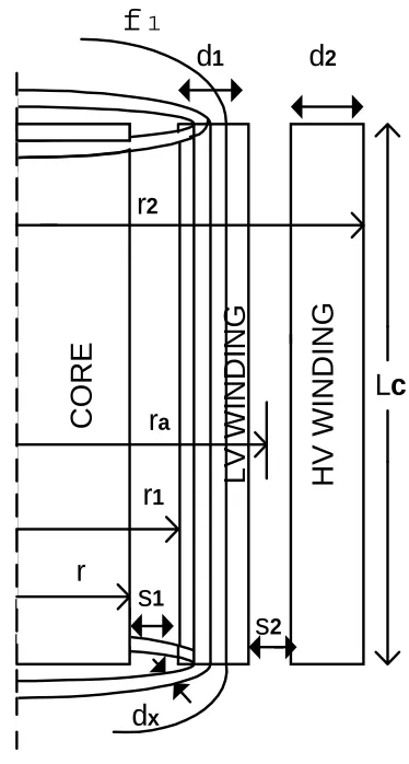
The previous assumptions are considered here in order to obtain a closed-form solution. Consider the path F1 in Figure 1, mmf for the path having distance x from the beginning of LV winding is [7]:
1 1 1
d
x
I
N
F
x=
(7)Rising x from 0 to d1 increases the magnetic
field intensity and approaches its peak value N1I1/Lc. A volume differential from LV winding
as shown in Figure 1, with height Lc, thickness dx and radius r+s1+x is considered. The
electromagnetic energy stored in this element
is [14]:
dv
H
dw
x x22
1
o
µ
=
(8)and the total energy is:
1 1 1 2
1 2 1
2
0
1 2
1 2 1 2 1
0 1
)
4
3
(
)
(
1 1
d
d
s
r
Lc
I
N
dx
x
x
s
r
Lcd
I
N
dw
W
d d
x
+
+
=
+
+
=
=
∫
∫
o
o
πµ
πµ
(9)
Similarly the stored energy in HV winding can be
LV WINDING
HV WINDING
d
2d
1L
c
r
1r
2CORE
s
2r
as
1r
d
xf
1Figure 1. The volume element of LV winding for energy
determined: 2 2 2 1 2 1 2 2 2 2 2 ) 4 3
(r s s d d d d Lc
I N
W =πµo + + + + − (10)
With a constant magnetic field intensity between the windings, Wa the electromagnetic
energy stored between them is:
2
2
0 a a
a
V
H
W
=
µ
(11)Hence: 2 2 1 1 2 2 2 2
)
2
(
r
s
d
s
s
Lc
I
N
W
a=
πµ
o+
+
+
(12)The stored energy for this two-winding transformer is: 2 2 1
2
1
LeqI
W
W
W
W
=
+
a+
=
(13)Using Equations 9-13, the inductance will be as follows: ] s r d ) 4 d 3 r ( d ) 4 d 3 r [( Lc N πµ 2 Leq 1 a 2 2 2 1 1 1 2 2 12 + − + + = o (14)
r1 , r2 and ra are defined as follows:
2
2 1 1 2 2 1 1 2 1 1s
d
s
r
r
d
s
d
s
r
r
s
r
r
a
=
+
+
+
+
+
+
+
=
+
=
(15) (16)A notable point is that if term (r1/3+d1/4) is
substituted by rave1/3 and term (r2/3-d2/4) in
replaced by rave2/3, Leq will be:
) s r 3 d r d r ( Lc N πµ 2 f π 2 Xeq 2 a 2 ave 1 ave 2 2 12 2
1 + +
= o
(17)
The following simplification is applied:
2 2 1 1 2 1
2
,
2
)
2
(
2
ave mt ave mt mt mtr
L
r
L
ra
L
L
π
π
π
=
=
=
+
(18)Equation 17 is converted into Equation 5. It means that the flux element method is an approximation of the energy method.
5. SIMULATION
5.1 A Single-Phase Transformer
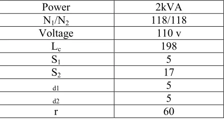
A small single-phase transformer with specifications given in Table 1 is simulated [12]. The image method result of this reference is used to compare the accuracy of different methods.Using the previous results of the transformer from Reference 12, the result of different methods can be compared. As shown in Table 2, the error using the energy method is lower than that of the
TABLE 1. Specifications of the Proposed Single-Phase Transformer. Dimensions are in mm.
Power 2kVA
N1/N2 118/118
Voltage 110 v
Lc 198
S1 5
S2 17
d1 5
d2 5
r 60
TABLE 2. Computations Results Using Different Methods.
Method Inductance (mH)
image method. Also the flux element method has larger error compared to the other two methods.
5.2 Three-Phase Distribution Transformers
Three types of three-phase distribution transformers with voltages 20/0.4 kV and connection group YZn5 with specification given in Table 3 are considered. Figure 2 shows the dimensions of the 25,50 and 100kVA transformers. The last column of Table 3 shows the result of short-circuit test of transformers in the factory. The specifications and the test results (last column) in Table 3 are measured for more than 100 distribution transformers.
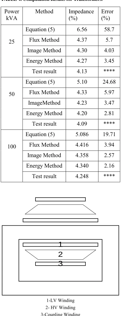
The short-circuit impedance has been
calculated using the above-mentioned methods. The results for these transformers have been summarized in Table 4. The result shows that energy method has the best accuracy compared to other methods for all of these distribution transformers.
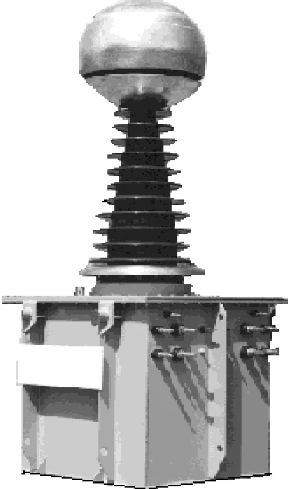
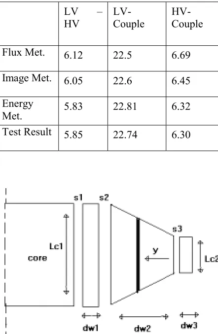
5.3 A Single-phase High Voltage Test
Transformer
The result of simulation of a 500 kVA, 250kV test transformer, illustrated in Figure 3 and designed by the authors and manufactured in Iran, is shown in Table 5. The schematic presentation of windings are in Figure 4.D3 D2 D1
L
cD1 : diameter of core, D2: diameter of primary winding
D3: diameter of secondary winding
Figure 2. A simple geometrical schematic Dimensions of the transformer.
Figure 3.A 250 kV, 500 kVA test transformer designed and
manufactured in Iran.
TABLE 3. Specifications of the Proposed Transformers.
Power kVA
N1 N2 D1 mm
D2 mm
D3 mm
V/N Zsc %
25 11 6
5224 10 5
11 0
13 5
2.3 0
4.1 3 50 88 3962 11
1 11 6
16 1
3.0 3
4.0 9 100 68 3062 12
2 12 7
17 7
3.9 2
It is noticeable that the transformer has 3 windings: low voltage, high voltage and coupling (for energy transmission to upper steps).
6. CONCLUSIONS
Different analytical methods for the leakage inductance of transformer calculation have been compared. It has been shown that the energy method is the most accurate one. Although the image method is accurate and convenient, it depends on the current of the image conductors. These results are compared by practical measurements for three types of transformers: small single-phase transformer, three-phase distribution transformers and a high voltage test transformer.
So by calculating stored electromagnetic energy in windings and distance between them leakage reactance will be calculated simply and accurately comparing to test result.
7. APPENDIX
Calculation of Leakage Reactance of
Test Transformer
The reactance betweenwindings calculated two by two and the detail of calculation is given here. The result shows that energy method is also reliable in this case.
Because of trapezoid shape of HV winding of test transformer according to Figure 5, the formula of 10 will be changed:
] C L
C L ln C L C L
C L ) C L k r (
) C L C L C L C L ( 3 k ) C L k 5 . 1 r ( C L 2
) C L C L ( ) C L k 3 r ( 2 1 [ w d
I N µ π W
2 1 2
1
2 2 2 2
2 1 2 2 2 1 2
2 2
2 1 2 2
2 2 2 2 2 2
− +
+ +
+ −
+ −
+ +
= o
(A1) TABLE 4. Computation Results for Transformers.
Power kVA
Method Impedance (%)
Error (%) Equation (5) 6.56 58.7
Flux Method 4.37 5.7 Image Method 4.30 4.03 Energy Method 4.27 3.45 25
Test result 4.13 **** Equation (5) 5.10 24.68 Flux Method 4.33 5.97 ImageMethod 4.23 3.47 Energy Method 4.20 2.81 50
Test result 4.09 **** Equation (5) 5.086 19.71 Flux Method 4.416 3.94 Image Method 4.358 2.57 Energy Method 4.340 2.16 100
Test result 4.248 ****
1
3
2
1-LV Winding 2- HV Winding 3-Coupling Winding
Considering Leakage reactance between LV and HV:
−
+ + +
+ −
+ + − +
+ + +
=
2 1
2 1
2 2 2 2 2 1 2 2 2 1
2 2
2 2
1 2 2 2 1
2 1 1 1
1 2 2 2
12
C L
C L ln C L C L
C L ) C L k r ( C L C L C L C L ( 3 k
) C L k 5 . 1 r ( C L 2 ) C L C L ( ) C L k 3 r ( 2 1 w d
C L
ras w d ) 4 w d 3 r ( C L
N µ f .
π
4
Xeq o
(A2) Where k is a constant.
8. LIST OF SYMBOLS
λ
Leakage flux N No. of turn of winding I currentLmt Mean length of one turn of winding
Lc length of window of core
d Width of winding
s1 Distance between core and LV windings
s,s2 Distance between LV and HV windings
rave1, rave2
Mean radius of HV and LV winding respectively
X Reactance of transformer
F Frequency of current of windings W Electromagnetic energy stored in active
part
Leq Equivalent inductance of transformer
Hx Magnetic field intensity in a distance x of
first layer of primary winding
9. REFERENCES
1. 1.Karsai, K., Kerenyi, D. and Kiss, L., "Large Power Transformers", Hungary, Elsevier, (1987).
2. Shima, Kazumasa and Miyoshi Takahshi, “Finite-Element Calculation of Leakage Inductances of a Sutured Salient-Pole Synchronous Machine with Damper Circuits”, IEEE Transaction on Energy Conversion, Volume 17, Number 4, (December 2002),
463- 470.
3. Branislaw Tomczuk, “Analysis of 3-D Magnetic Fields in High Leakage Reactance Transformers”, IEEE Transaction on Magnetics, Vol. 3, No.5, (September
1994), 2734-2738.
4. Guemes Alonso and Antonio, J., “A New Method for Calculating of Leakage Reactances and Iron Losses in Transformers”, 5th International Conference on Electrical Machines and Systems, (ICEMS 2001), Vol. 1, 178-181.
5. Frederic Robert and Pierre Mathys, “Ohmic Losses Calculation in SMPS Transformers: Numerical Study of Dowell’s Approach Accuracy”, IEEE Transaction on Magnetics, Vol. 34, No.4, (July 1998), 1255-1257.
6. Liew, M. C. and Bodger, P. S., “Partial Transformer Design Using Reverse Modeling Techniques”, IEE Proc. Electrical Power Application, Vol. 148, No. 6,
(November 2001), 513- 519.
TABLE 5. Result of Methods for the Test Transformer.
LV –
HV
LV- Couple
HV- Couple
Flux Met. 6.12 22.5 6.69
Image Met. 6.05 22.6 6.45 Energy
Met. 5.83 22.81 6.32
Test Result 5.85 22.74 6.30
7. Agrawal, R. K., "Principles of Electrical Machines Design", Third Edition, India, (1997).
8. Turowski, J., Turowski, M. and Kopec, M., "Methods of Three-Dimensional Network Solution of Leakage Field of Three-Phase Transformers", IEEE Transaction on Magnetics, Vol. 26, No. 5, (September
1990), 2911-2919.
9. Blume, L. F., et al., "Transformer Engineering", Second Edition, John Wily and Sons, (1951).
10. Allan, D. J. and Harrison, T. H., "Design for Reliability of High Voltage Power Transformers and Reactors", GEC Rev., Vol. 1, (1985).
11. Smith, J., “Transformer Reactance Calculations
with Digital Computers”, AIEE Trans., (1956),
261-267.
12. DeLeon, F. and Semlyen, A., "Efficient Calculation of Elementary Parameters of Transformers", IEEE Trans. on Power Delivery, Vol. 7, No. 1, (January 1992),
376-383.
13. Wilcox, D. J., Hurley, W. G. and Conlon, M., "Calculation of Self and Mutual Impedances Between Section of Transformer Windings", IEE Proceeding,
Volume 136, Part C, Number 5, (September 1989), 308-314.
14. Kruse, Paul C., "Analysis of Electric Machinery ",