*Corresponding author:Adarsh Kumar ISSN: 0976-3031
INNOVATIVE APPROACH USING FUZZY BASED MAXIMUM POWER POINT CONTROLLING
TECHNIQUES FOR HARMONIC REDUCTION IN GRID CONNECTED SOLAR
Adarsh Kumar
Department of Electrical Eng
DOI: http://dx.doi.org/10.24327/ijrsr.2019.100
ARTICLE INFO ABSTRACT
This research reviews power quality problems
radiations and the variation in the load connected with the system. These power quality problems like voltage fluctuation, voltage distortion, and harmonics at the L.T. line are generated by source and load also at the PCC. This paper comprises about power quality problems and mitigation technique on the by using active filters.
Age of fossil fuel as source of energy is constantly getting extinct. Demand of fuel and energy is exponentially rising w
overcome these critical situations we can use renewable resources at our disposal from which energy can be tapped. Photovoltaic cell converts solar energy to direct electric energy.
INTRODUCTION
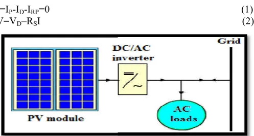
For the synchronization of utility grid and grid connected PV system, some condition has to satisfy like voltage level, frequency and phase sequence matching. This synchronization is done by PV inverter which having advance power electronics technology.
The power-voltage relationship or current-voltage relationship of the cell can generally be representing the Electrical characteristics of a PV unit. The changes of solar irradiance on the cell and the cell temperature are directly varies these characteristics.
A proper simulation model is needed to convert the changes of temperature and radiation on generated voltage and current of the PV arrays. So that at the different weather conditions, the dynamic performance of PV system can be analyze. Solar cell is basically a photovoltaic cell form of p-n junction.
It when exposed to sunlight absorbs some energy greater than band-gap. This creates some hole-electron pairs proportional to incident radiations. These carriers are affected by internal
Available Online at
International
Vol. 10, Issue, 04(A), pp. 31655
Copyright © Adarsh Kumar, Shanti Rathore and Qureshi M.F
terms of the Creative Commons Attribution License, which permits unrestricted use, distribution and reproduction in any medium, provided the original work is properly cited.
Article History:
Received 12th January, 2019 Received in revised form 23rd February, 2019
Accepted 7th March, 2019 Published online 28th April, 2019
Key Words:
Photovoltaic (PV), MPPT, ANFIS, Matlab/Simulink, SAPF, Power Quality Issues, Fuzzy logic controller (FLC), Power quality (PQ), Renewable energy sources (RES), DCDC boost converter, Power Quality, ANFIS Controller, Voltage Sag, Voltage Swell.
Research Article
INNOVATIVE APPROACH USING FUZZY BASED MAXIMUM POWER POINT CONTROLLING
TECHNIQUES FOR HARMONIC REDUCTION IN GRID CONNECTED SOLAR
Adarsh Kumar, Shanti Rathore and Qureshi M.F
of Electrical Engineering., CVRU, Bilaspur, Chhattishgarh
DOI: http://dx.doi.org/10.24327/ijrsr.2019.1004.3308
ABSTRACT
This research reviews power quality problems that raises by changes in weather conditions like solar radiations and the variation in the load connected with the system. These power quality problems like voltage fluctuation, voltage distortion, and harmonics at the L.T. line are generated by source d load also at the PCC. This paper comprises about power quality problems and mitigation technique on the by using active filters.
Age of fossil fuel as source of energy is constantly getting extinct. Demand of fuel and energy is exponentially rising with time. At the same time energy cost is also continuously increasing. To overcome these critical situations we can use renewable resources at our disposal from which energy can be tapped. Photovoltaic cell converts solar energy to direct electric energy.
For the synchronization of utility grid and grid connected PV system, some condition has to satisfy like voltage level, frequency and phase sequence matching. This synchronization is done by PV inverter which having advance power electronics
voltage relationship of the cell can generally be representing the Electrical characteristics of a PV unit. The changes of solar irradiance on the cell and the cell temperature are directly varies these
A proper simulation model is needed to convert the changes of temperature and radiation on generated voltage and current of the PV arrays. So that at the different weather conditions, the dynamic performance of PV system can be analyze. Solar cell
n junction.
It when exposed to sunlight absorbs some energy greater than electron pairs proportional to incident radiations. These carriers are affected by internal
electric fields of p-n junction and forms photo current proportional to solar isolation. PV cells have nonlinear characteristics which vary with radiation intensity and temperature.
PV cells produces less than 3W at 0.5 to 0.6 Volts, so cells are connected in series to produce enough power. The terminal equation for the current and voltage of the array of PV panels are given as under (figure 2)
I=IP-ID-IRP=0
V=VD–RSI
Figure 1 Grid connected PV system
Available Online at http://www.recentscientific.com
International Journal of Recent Scientific Research
Vol. 10, Issue, 04(A), pp. 31655-31662, April, 2019
Adarsh Kumar, Shanti Rathore and Qureshi M.F, 2019, this is an open-access article distributed under the terms of the Creative Commons Attribution License, which permits unrestricted use, distribution and reproduction in any
, provided the original work is properly cited.
CODEN: IJRSFP (USA)
INNOVATIVE APPROACH USING FUZZY BASED MAXIMUM POWER POINT CONTROLLING
TECHNIQUES FOR HARMONIC REDUCTION IN GRID CONNECTED SOLAR POWER SYSTEM
M.F
ing., CVRU, Bilaspur, Chhattishgarh
that raises by changes in weather conditions like solar radiations and the variation in the load connected with the system. These power quality problems like voltage fluctuation, voltage distortion, and harmonics at the L.T. line are generated by source d load also at the PCC. This paper comprises about power quality problems and mitigation Age of fossil fuel as source of energy is constantly getting extinct. Demand of fuel and energy is ith time. At the same time energy cost is also continuously increasing. To overcome these critical situations we can use renewable resources at our disposal from which energy can be tapped. Photovoltaic cell converts solar energy to direct electric energy.
n junction and forms photo current proportional to solar isolation. PV cells have nonlinear characteristics which vary with radiation intensity and
PV cells produces less than 3W at 0.5 to 0.6 Volts, so cells are to produce enough power. The terminal equation for the current and voltage of the array of PV panels
(1) (2)
Grid connected PV system
International Journal of
Recent Scientific
Research
access article distributed under the terms of the Creative Commons Attribution License, which permits unrestricted use, distribution and reproduction in any
Adarsh Kumar, Shanti Rathore and Qureshi M.F., Innovative Approach using Fuzzy Based Maximum Power Point Controlling Techniques for Harmonic Reduction in Grid Connected Solar Power System
IP=
I = I ( − 1)
IPh= Light Generated Current, V= Terminal Voltage of the Cell,
Id = Diode Current, Io = Saturation Current, I
Current, q = Electron Charge, k = Boltzmann Constant, T =Temperature, RD = Series Resistance, RP = Shunt Resistance
Figure 2 Equivalent circuit Diagram of PV cell
Boost Converter and Inverter
Boost converter increases voltage level for inverter and control MPPT. Output voltage of boost converter is higher than input voltage. Input current is same as inductor current and hence it is not discontinuous as buck convertor and hence input filter requirements are relaxed in boost converter.
If solar panels of high rating are implemented then requirement of boost converter can also be relaxed and switching loss in converter can be saved. PV Panels generate DC Voltage and to connect panels to grid DC power has to be converted to AC Power. We require inverter to convert DC to sinusoidal AC before connecting to grid. Output voltage and frequency should be same as that of grid voltage and frequency. Many inverter topologies are available.
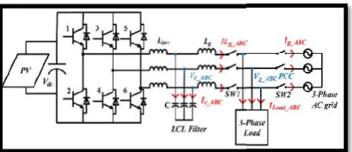
In proposed scheme PWM (pulse width modulated) Voltage Source Inverter is selected d-q theory with phase. Output of the Inverter is near to Sinusoidal. 6 switches are used and its switching is controlled by discrete PWM signals. Electrical diagram for inverter is shown in Figure 3.
Figure 3 PWM 3 phase inverter with passive filter
Possible Effects on Distribution System Due to Grid Connected PV System
In the renewable energy system, PV system is more reliable sources of energy. So that it attracting considerable commercial interest. For distribution network, the connection of distributed PV system to utility grid may causes several operational problems. The severity of these problems distinguishes on the basis of the percentage of PV penetration and the geography of the installation. So that, knowing the possible impact of distributed grid-connected PV systems on distribution networks
Innovative Approach using Fuzzy Based Maximum Power Point Controlling Techniques for Harmonic Reduction in
(3) (4) = Light Generated Current, V= Terminal Voltage of the Cell,
= Saturation Current, IRP = Shunt
Current, q = Electron Charge, k = Boltzmann Constant, T = Shunt Resistance
Equivalent circuit Diagram of PV cell
Boost converter increases voltage level for inverter and control MPPT. Output voltage of boost converter is higher than input voltage. Input current is same as inductor current and hence it is not discontinuous as buck convertor and hence input filter
If solar panels of high rating are implemented then requirement of boost converter can also be relaxed and switching loss in converter can be saved. PV Panels generate DC Voltage and to ower has to be converted to AC Power. We require inverter to convert DC to sinusoidal AC before connecting to grid. Output voltage and frequency should be same as that of grid voltage and frequency. Many inverter
eme PWM (pulse width modulated) Voltage q theory with phase. Output of the Inverter is near to Sinusoidal. 6 switches are used and its switching is controlled by discrete PWM signals. Electrical
PWM 3 phase inverter with passive filter
Possible Effects on Distribution System Due to Grid
In the renewable energy system, PV system is more reliable sources of energy. So that it attracting considerable commercial interest. For distribution network, the connection of distributed PV system to utility grid may causes several operational The severity of these problems distinguishes on the basis of the percentage of PV penetration and the geography of the installation. So that, knowing the possible impact of connected PV systems on distribution networks
can provide feasible solutions before real implementations.
Overvoltage
PV systems are designed in that way so it can fully utilize solar energy. It is happened only when system is operating near unity power factor. In this case, the reactive power flow system changes due to active power from PV system injects into utility grid. Hence, due to the lack of reactive power, voltage of near buses can be increased. The produced over voltage can have negative effects on the operation of both the utility and customer sides.
Harmonics
Harmonic distortion is a serious power quality problem that due to use power electronics devices in PV system like power inverter that convert DC power into AC power. Due to inverter, the produced harmonics can cause series a
resonances, overheating in transformer and capacitor bank, and reliability of power systems may reduce due to false operation of protection devices, inverter and PWM generator.
Power Fluctuation
The fluctuation of the output power of PV syste
main factors that may cause severe operational problems for the utility network. The variation in solar irradiance occurs due to the movement of clouds and may continue for minutes or hours, depending on wind speed, the type and size of pa clouds, the area covered by the PV system. These variations in solar irradiation result in power fluctuation. And this Power fluctuation may cause for unacceptable voltage fluctuation, voltage flickers, power swings in lines, and over
loadings.
Frequency Fluctuation
Frequency is most important factor in power quality. Frequency fluctuation may causes due to imbalance between the consumed and the produced power. The small size of PV systems causes the frequency fluctuation to be negligible compared with other renewable energy
However, increasing the penetration levels and no. of distributed PV systems becomes more severe for these issues. Inrush Current
The difference between grid voltage and PV system voltage may introduce an inrush current that flows between the PV system and the utility grid at the time of connection, and an exponentially decays to zero. Nuisance trips, thermal stress, and other problems may causes due to the inrush current. These problems are occurs due to changes in grid connected PV systems. These problems can be eliminated. Harmonics, over voltage due to excess reactive power in the grid, voltage fluctuation by traditional methods like passive filters. But in traditional method or passive filter have
the problems. The value for inductors and capacitors are kept fixed. Because of that it can work for fix range of harmonics. It doesn’t work for reactive power. It can’t inject excess voltage in the system or draw excess voltage fro
Voltage fluctuation. If value of inductance and capacitor will increased, the impedance of the grid may be changes. So it causes other problems. So that active filter is way to improve
Innovative Approach using Fuzzy Based Maximum Power Point Controlling Techniques for Harmonic Reduction in
e solutions before real-time and practical
PV systems are designed in that way so it can fully utilize solar energy. It is happened only when system is operating near unity power factor. In this case, the reactive power flow of the system changes due to active power from PV system injects into utility grid. Hence, due to the lack of reactive power, voltage of near buses can be increased. The produced over-voltage can have negative effects on the operation of both the
Harmonic distortion is a serious power quality problem that due to use power electronics devices in PV system like power inverter that convert DC power into AC power. Due to inverter, the produced harmonics can cause series and parallel resonances, overheating in transformer and capacitor bank, and reliability of power systems may reduce due to false operation of protection devices, inverter and PWM generator.
The fluctuation of the output power of PV systems is one of the main factors that may cause severe operational problems for the utility network. The variation in solar irradiance occurs due to the movement of clouds and may continue for minutes or hours, depending on wind speed, the type and size of passing clouds, the area covered by the PV system. These variations in solar irradiation result in power fluctuation. And this Power fluctuation may cause for unacceptable voltage fluctuation, voltage flickers, power swings in lines, and over- and under
Frequency is most important factor in power quality. Frequency fluctuation may causes due to imbalance between the consumed and the produced power. The small size of PV systems causes the frequency fluctuation to be negligible compared with other renewable energy-based resources. However, increasing the penetration levels and no. of distributed PV systems becomes more severe for these issues.
International Journal of Recent Scientific Research Vol. 10, Issue, 0
power quality by eliminating these problems. It cov
problems with the system from generating as well as load of system.
For the last two decades renewable energy is very well known. Renewable energy sources are forecasted to turn out to be competitive with conventional power generation systems. The efforts to widen the use of renewable energy resources instead of polluting fossil fuels and other forms have been raised. Renewable energy source such as photovoltaic (PV), hydro, fuel and wind generation systems have obtained much attention newly as alternative means of producing electricity. The PV energy as an alternative energy source has been extensively employed since it is pollution free, plentiful, and largely accessible.
The PV power generation applications can be categorized into, stand-alone systems and grid connected systems. A standalone system needs the battery bank to accumulate the PV energy and is appropriate for a low power system. Alternatively, a grid connected system does not need the battery bank and has turned out to be the primary method for high power applications. Power quality is manipulated by three factors such as generation aspects, consumer aspects and network aspects. Effects of poor power quality like sags, swells, distortion in waveform, harmonics, and reactive power generation has affected both grid and utility sectors. PV cells and power quality conditioner for voltage sags suggests to work out power quality issue by means of a voltage controlled converter that performs as a shunt controller enhancing the voltage quality in case of small voltage dips and in the presence of nonlinear loads. For stabilizing and improving voltage profile in power systems and to balance current harmonics and unbalanced load current shunt controllers can be employed as static VAR generator.
PV systems can improve the operation of power systems by enhancing the voltage profile and by decreasing the energy losses of distribution feeders, the maintenance costs, and the loading of transformer tap changers during peak hours. Planned for enhancing the energy competence and power quality issues with increasing demand, grid connected solar PV systems are taking a superior place. The injected grid voltage and current with the active filter facilitated and with dissimilar power factors. The reactive power is supplied to the grid, and the total harmonic distortion (THD) of the grid current rise. While the low power devices with restricted current capability would be implemented in an actual application, the power losses of the full-bridge driving the common-mode transformer would raise. The power switches dependability decreased the size of the power converter increased. The power losses, THD, and errors on dissimilar parts of the system for which the behavior of the system varies considerably and instability may happen inside the system. This paper proposes PI controller based power quality analysis in grid connected Photovoltaic (PV) system. Grid Connected PV System with PI Controller
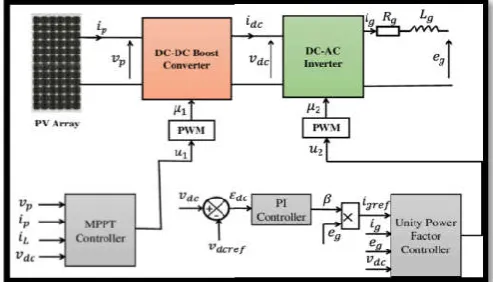
In figure 4, described about the grid connected PV system with PI controller. Here, PV system is the source and it generates electricity from the solar energy. The PV connected to the grid via inverter, LC filter and point of common coupling (PCC). The inverter converts the DC supply into AC and fed to the LC filter. The main aim of the grid connected PV topology is give
International Journal of Recent Scientific Research Vol. 10, Issue, 04(A), pp. 31655-31662
power quality by eliminating these problems. It covers many problems with the system from generating as well as load of For the last two decades renewable energy is very well known. Renewable energy sources are forecasted to turn out to be competitive with conventional power generation systems. The efforts to widen the use of renewable energy resources instead of polluting fossil fuels and other forms have been raised. Renewable energy source such as photovoltaic (PV), hydro, fuel and wind generation systems have obtained much attention ernative means of producing electricity. The PV energy as an alternative energy source has been extensively employed since it is pollution free, plentiful, and largely
The PV power generation applications can be categorized into, ystems and grid connected systems. A standalone system needs the battery bank to accumulate the PV energy and is appropriate for a low power system. Alternatively, a grid connected system does not need the battery bank and has method for high power applications. Power quality is manipulated by three factors such as generation aspects, consumer aspects and network aspects. Effects of poor power quality like sags, swells, distortion in waveform, harmonics, and reactive power ation has affected both grid and utility sectors. PV cells and power quality conditioner for voltage sags suggests to work out power quality issue by means of a voltage controlled converter that performs as a shunt controller enhancing the in case of small voltage dips and in the presence of nonlinear loads. For stabilizing and improving voltage profile in power systems and to balance current harmonics and unbalanced load current shunt controllers can be employed as
systems can improve the operation of power systems by enhancing the voltage profile and by decreasing the energy losses of distribution feeders, the maintenance costs, and the loading of transformer tap changers during peak hours. Planned e energy competence and power quality issues with increasing demand, grid connected solar PV systems are taking a superior place. The injected grid voltage and current with the active filter facilitated and with dissimilar power is supplied to the grid, and the total harmonic distortion (THD) of the grid current rise. While the low power devices with restricted current capability would be implemented in an actual application, the power losses of the mode transformer would raise. The power switches dependability decreased the size of the power converter increased. The power losses, THD, and errors on dissimilar parts of the system for which the behavior of the ty may happen inside the system. This paper proposes PI controller based power quality analysis in grid connected Photovoltaic (PV) system. Grid Connected PV System with PI Controller
In figure 4, described about the grid connected PV system with PI controller. Here, PV system is the source and it generates electricity from the solar energy. The PV connected to the grid via inverter, LC filter and point of common coupling (PCC). erter converts the DC supply into AC and fed to the LC filter. The main aim of the grid connected PV topology is give
a constant power flow parameters for both the normal and abnormal conditions. During the grid faulty condition develops the PQ issues in the grid connected PV systems. By employing the suggested control technique the reported problems can be corrected. The proposed PI control technique is used to generate the control pulses of the inverter by utilizing the grid parameters.
Figure 4 Block diagram of the grid connected
PV system with controller The LC filter is employed as the output filter in order to limit the higher order harmonics coming from the inverter switching behavior as it can be seen in the figure 4.4. The grid parameters like v
are essential to decide the grid side PQ, which is used to determine the active and reactive power of the grid. The PQ problem is identified through the error calculation between the actual grid side parameters and the reference power va attained from the PV system.
Figure 5 Controller diagram of the grid connected PV system
In the PV system, Maximum Power Point Tracking technique (MPPT) is utilized for the power value calculation. The control diagram under grid fault condition is
figure 5. The error calculation is defined in the following equation (4) and (5).
∆P=[P(act)–P(ref)] ∆Q=[P(act)–P(ref)] Where, ΔP and ΔQ are the error values of reactive power; P(act) and Q
reactive power; P(ref ) and Q
reactive power. The error values are allowed to the PI controller, which is described in the following figure 6. The outcome of the PI controller is used for the evaluation of reference grid current and which will be utilized for generating the appropriate control pulses of the inverter.
31662, April, 2019
a constant power flow parameters for both the normal and abnormal conditions. During the grid faulty condition develops he grid connected PV systems. By employing the suggested control technique the reported problems can be corrected. The proposed PI control technique is used to generate the control pulses of the inverter by utilizing the grid
diagram of the grid connected
PV system with controller The LC filter is employed as the output filter in order to limit the higher order harmonics coming from the inverter switching behavior as it can be seen in the figure 4.4. The grid parameters like voltage and current are essential to decide the grid side PQ, which is used to determine the active and reactive power of the grid. The PQ problem is identified through the error calculation between the actual grid side parameters and the reference power values
Controller diagram of the grid connected PV system
In the PV system, Maximum Power Point Tracking technique (MPPT) is utilized for the power value calculation. The control diagram under grid fault condition is described in the following figure 5. The error calculation is defined in the following
(5) P(ref)] (6)
Adarsh Kumar, Shanti Rathore and Qureshi M.F., Innovative Approach using Fuzzy Based Maximum Power Point Controlling Techniques for Harmonic Reduction in Grid Connected Solar Power System
Figure 6 PI controller structure
In normal condition, the grid side power flow parameters are in normal condition. If any fault condition occurs, the parameters are changed from the normal condition, because of the amplitude variation of the grid side voltage and current. According to the variation of the grid side parameters, the control signals are generated using the proposed PI controller. The proposed method is implemented in the MATLAB/Simulink platform.
Results Obtained with PI
The implementation of the proposed control technique is carried out in the MATLAB/Simulink 7.10.0 (R2012a) platform, 4GB RAM and Intel(R) core(TM) i5. Here, the grid connected PV system is modelled and the PQ of the system is analyzed through the PI controller technique. The proposed control technique produces control pulses of the inverter for both the normal and abnormal conditions of the grid. The simulink model of the grid connected PV system and control technique is described in the figure 7.
Figure 7 Simulink model: Grid connected PV model
(a)
(b)
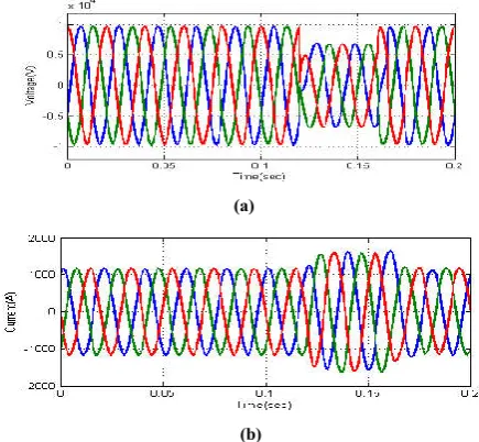
Figure 8 Grid at normal condition: (a) Voltage (b) Current
To analyze the PQ improvement using PI controller, grid parameters are required like voltage, current, real power and reactive power for both the normal and abnormal conditions. Initially the performance of the grid connected PV system is tested under normal condition, which ensures that the system have no fault at the grid side. The simulation time required for the testing process is 0 to 0.2 seconds.
(a)
(b)
Figure 9 Grid at fault condition: (a) Voltage (b) Current
The grid side voltage, current, real power and reactive power at normal condition are described in the Figure 8. It shows that the grid voltage 10kV, grid current is 1000A, real power is 100MW and reactive power is 0.35MVAr. The grid side parameters under fault condition are described in the Figure 9. Here, three phases to ground fault was introduced in the grid side at the time duration 0.12 to 0.15 seconds.
(a)
(b)
Figure 10 Using PI controller: (a) Voltage; (b) Current
International Journal of Recent Scientific Research Vol. 10, Issue, 04(A), pp. 31655-31662, April, 2019
parameters are illustrated in the figure10. It shows that the grid voltage has amplitude reduction 23% from the original value at the fault applied time 0.12 to 0.15 seconds.
Performance of Grid-Connected PV System Based on SAPF for Power Quality Improvement
This paper presents the design of a shunt Active Power Filter (SAPF) for grid-connected photovoltaic systems. The proposed system injects PV power into the grid, by feeding the SAPF; to eliminate harmonics currents and compensate reactive power produced by nonlinear loads.
To inject the photovoltaic power to the grid we use a boost converter controlled by a Fuzzy logic (FLC) algorithm for maximum power point tracking (MPPT). The SAPF system is based on a two-level voltage source inverter (VSI); P-Q theory algorithm is used for references harmonic currents extraction. The overall system is designed and developed using MATLAB /Simulink software. Simulation results confirm the performance of the grid-connected photovoltaic system based on SAPF. For the MPPT controller, the results show that the proposed FLC algorithm is fast in finding the MPPT than conventional techniques used for MPPT like perturbed and observed (P&O). The simulated compensation system shows its effectiveness such as the sinusoidal form of the currents and the reactive power compensation. The proposed solution has achieved a low Total Harmonic Distortion (THD), demonstrating the efficiency of the presented method. Also, the results determine the performances of the proposed system and offer future perspectives of renewable energy for power quality improvement.
The increasing seriousness of energy shortage crises and environmental concerns has made the development of an intelligent grid, become one of the most pressing issues researched among scholars. The integration of renewable sources, such as small-scale winds, photovoltaic, or fuel cells, into distribution networks brings clean and convenient power supply. At the same time, the intermittent and fluctuation of primary sources, the increasing application of the interfaced power electric devices, and the multiple non-linear loads bring about covert issues of power quality. These nonlinear loads appear to be prime sources of harmonic distortion in a power distribution system. Harmonic currents produced by nonlinear loads are injected back into power distribution systems through the point of common coupling (PCC).
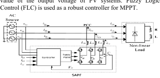
These perturbations (harmonics) are the origin of many problems and affect electrical equipment connected to the power supply. In order to enhance the power quality by considering current distortion limits for non-linear loads, many systems have been proposed. This paper presents an analysis and simulation of PV systems, connected in SAPF, for harmonics elimination and reactive power compensation. The SAPF injects the current in the same amplitude and reverse phase of the load current to compensate for the source current. Figure11 shows the proposed system; the three phase SAPF system is based on a three-phase inverter. The shunt APF is designed to be connected in parallel with the nonlinear load. It is connected to the distribution network in the PCC. For the Shunt Active Filter reference current computation, we used the P-Q Theory. Also, a DC/DC converter can be used to adjust the
value of the output voltage of PV systems. Fuzzy Logic Control (FLC) is used as a robust controller for MPPT.
Figure 11 Block diagram of SAPF fed by PV systems
Configuration of A SAPF fed by PV Systems
Photovoltaic Cell Equivalent circuit
A single-diode PV cell model form is illustrated in Figure12, including four components: a photo current source, Iph, a diode parallel to the source, a series resistor, Rs, a shunt resistor, Rsh. The DC current generated, Iph. The relationship between the cell terminal current and voltage is the following.
Figure 12 A single-diode PV cell model MPPT control algorithms
To increase the efficiency of the PV system, it is required to operate at the maximum power point (MPP). Several methods have been developed for PV systems, and for all conventional MPPT techniques, the main problem is how to obtain optimal operating points (voltage and current) automatically at maximum PV output power under variable atmospheric conditions. The main aspects referred to these algorithms are low response speed, errors in Tracking under rapidly changing atmospheric conditions. On the other hand fuzzy logic has received much attention from a number of researchers in the area of power electronics. Fuzzy logic control is somewhat easy to implement, because it does not need exact mathematical model of the plant.
Fuzzy MPPT Controller
Adarsh Kumar, Shanti Rathore and Qureshi M.F., Innovative Approach using Fuzzy Based Maximum Power Point Controlling Techniques for Harmonic Reduction in Grid Connected Solar Power System
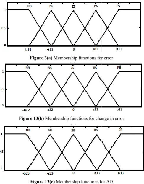
matrix are fuzzy sets of error (e), change of error ( change of duty ratio (ΔD) to the converter.
The fuzzy rules shown in Table 1 are employed for controlling the DC–DC converter such as the maximum power of the PV generator is reached. As an example, the rule in Table 1: If (E is NB) and (CE is NB) then (D is ZE). It is necessary to transform this fuzzy information into deterministic information, this transformation is called defuzzification. The membership functions for the variable are shown in Figure 13.
Figure 3(a) Membership functions for error
Figure 13(b) Membership functions for change in error
Figure 13(c) Membership functions for ΔD
Proposed Inverter Control Technique
The proposed system consists of PV system, Boost chopper, DC-link capacitor, two-level voltage source inverter (VSI) connected at the PCC to a three-phase grid through the interface inductances. The compensator reference current is calculated from the sensed grid current drawn by the nonlin load. In the literature, many control techniques have been proposed for the extraction of harmonics currents. The p theory was proposed in 1983 by Akag,
Table 1 Fuzzy rules for maximum power of the PV
generator
dee E CE D
E NB NB ZE
CE NS ZE PB
D ZE PB PS
Innovative Approach using Fuzzy Based Maximum Power Point Controlling Techniques for Harmonic Reduction in
), change of error (de) and
The fuzzy rules shown in Table 1 are employed for controlling DC converter such as the maximum power of the PV is reached. As an example, the rule in Table 1: If (E is NB) and (CE is NB) then (D is ZE). It is necessary to transform this fuzzy information into deterministic information, this transformation is called defuzzification. The membership
variable are shown in Figure 13.
Membership functions for error
Membership functions for change in error
Membership functions for ΔD
system, Boost chopper, level voltage source inverter (VSI) phase grid through the interface inductances. The compensator reference current is calculated from the sensed grid current drawn by the nonlinear load. In the literature, many control techniques have been proposed for the extraction of harmonics currents. The p-q
Figure 14 Block diagram for the p
Figure 15 Simulink model using fuzzy based MPPT
Figure 16 Responses of the two MPPT controllers (fuzzy and P&O), irradiation G and temperature T are variables
RESULTS AND DISCUSSION
As shown in Figure 16, for this test, we have varied by steps, both the irradiation S and temperature T at very short times. The main aspects referred of the P&O algorithm are, oscillations around the MPP in steady state; low tracking speed; Simulation results confirm that the fuzzy controller operates much better than the P&O controller. Figure 17(a)
shows the source current waveform deformed before filtering. The active filter has imposed a sinusoidal source current
waveform instantaneously as illustrated in Figure 17(a). The load current waveforms are in phase as illustrated in Figure 17(b).The shunt APF supplied by PV array is injected current Iinj as shown in Figure 17(c). The obtained current and voltage
waveforms are in phase as illustrated in Figure 18. Figure 19 shows the spectrum analysis of the source current with/without a PV-SAPF.
Fuzzy rules for maximum power of the PV
D
ZE PB PS
Innovative Approach using Fuzzy Based Maximum Power Point Controlling Techniques for Harmonic Reduction in
Block diagram for the p–q theory
Simulink model using fuzzy based MPPT controller
Responses of the two MPPT controllers (fuzzy and P&O), irradiation G and temperature T are variables
RESULTS AND DISCUSSION
As shown in Figure 16, for this test, we have varied by steps, both the irradiation S and temperature T at very short times. The main aspects referred of the P&O algorithm are, oscillations around the MPP in steady state; low tracking ults confirm that the fuzzy controller operates much better than the P&O controller. Figure 17(a)
shows the source current waveform deformed before filtering. The active filter has imposed a sinusoidal source current
International Journal of Recent Scientific Research Vol. 10, Issue, 0
Figure 17 (a) Supply current (b) Load current (c) Harmonic current of phase generated by the SAPF PV system
Figure 18 Waveform form current and voltage during SAPF operation
The current THD (total harmonic distortion) is reduced from 31.35% to 3.25% on the grid network, which confirms the good quality of filtering after using the PV-SAPF, the simulation results show a good filtering of harmonic currents and a perfect compensation of reactive power.
Figure 19 Spectrum analysis of the source current with/without a PV
Evaluation of Power Quality Issues
Figure 20 shows the performance of the grid
system with variable irradiation level. Under the variable irradiation level VSC controller is able to control the DC bus voltage and power factor at all solar radiations.
Figure 20 Grid connected PV with variable irradiation level
International Journal of Recent Scientific Research Vol. 10, Issue, 04(A), pp. 31655-31662
(a) Supply current (b) Load current (c) Harmonic current of phase generated by the SAPF PV system
form current and voltage during SAPF operation
The current THD (total harmonic distortion) is reduced from 31.35% to 3.25% on the grid network, which confirms the good SAPF, the simulation ing of harmonic currents and a perfect
Spectrum analysis of the source current with/without a PV-SAPF
Figure 20 shows the performance of the grid-connected solar variable irradiation level. Under the variable irradiation level VSC controller is able to control the DC bus voltage and power factor at all solar radiations.
Grid connected PV with variable irradiation level
Table 2 THD for grid voltage,
before filtering and after filtering and DC link voltage Signals of the grid connected
PV system for which THD has been calculated
Grid voltage Grid current Inverter voltage before filter
Inverter voltage after filter DC bus voltage( w.r.t. DC
fundamental value)
Total harmonic distortion (THD) is calculated using FFT analysis tool of MATLAB. The %THD is calculated for grid voltage, grid currents, inverter voltage before filtering and after filtering and DC link voltage and shown in the Table 2. Harmonics in all the signals are satisfying the IEEE limits. Figure 21 shows the performance of grid
system for constant irradiation. The wa
voltages, grid currents, solar irradiations, and DC bus voltage, active power respectively. In this figure, results are shown for constant irradiations (1000W/m2). DC bus voltage is maintained constant at 500V. Power factor is achieve
grid voltages and grid currents are in phase.
Figure 21 Performance analysis with constant irradiation
Figure 22 Performance analysis with variable irradiation
CONCLUSION
This paper provides a complete overview for the analysis of power quality related issues along with the modeling and control of grid connected photovoltaic system. Synchronous reference frame theory based controller has been used to control the grid side Power Factor. The results are obtained using MATLAB software and in Simulink environment for constant and variable irradiation and also in terms of DC link voltage regulation, Power factor and harmonic analysis. %THD has been calculated for grid side voltag
voltage and DC link voltage and presented in bar forms. The
31662, April, 2019
THD for grid voltage, grid currents, inverter voltage before filtering and after filtering and DC link voltage
Signals of the grid connected PV system for which THD
Power Quality evaluation in terms of
THD 0.06% 0.042%
voltage before filter 39.4%
Inverter voltage after filter 3%
DC bus voltage( w.r.t. DC
0.08%
Total harmonic distortion (THD) is calculated using FFT analysis tool of MATLAB. The %THD is calculated for grid inverter voltage before filtering and after filtering and DC link voltage and shown in the Table 2. Harmonics in all the signals are satisfying the IEEE limits. Figure 21 shows the performance of grid-connected solar system for constant irradiation. The waveform shows the grid voltages, grid currents, solar irradiations, and DC bus voltage, active power respectively. In this figure, results are shown for constant irradiations (1000W/m2). DC bus voltage is maintained constant at 500V. Power factor is achieved unity as grid voltages and grid currents are in phase.
Performance analysis with constant irradiation
Performance analysis with variable irradiation
Adarsh Kumar, Shanti Rathore and Qureshi M.F., Innovative Approach using Fuzzy Based Maximum Power Point Controlling Techniques for Harmonic Reduction in Grid Connected Solar Power System
present article presents an analysis and simulation of a three-phase SAPF fed by PV systems. An MPPT fuzzy logic controller is employed to feed the grid by the maximum allowable PV power. The proposed system has been simulated in MATLAB/SIMULINK software. This system is used to eliminate harmonics and to compensate reactive power generated by nonlinear loads. Performances of the shunt APF are related to the current references quality.
This method is very important because it allows harmonic currents and reactive power compensation simultaneously. Simulation results show that the current obtained after filtering and the voltage waveforms are in phase. Also, the current THD is reduced from 31.36% to 3.25% which confirms the good filtering quality of harmonic currents and the perfect compensation of reactive power which improve the power quality.
This paper proposed a PI controller based PQ analysis in the grid connected PV system. The mentioned results show that with PI controller, the percentage total harmonic distortion is reduced. The PI controller only utilizes the fixed gain parameters such as KP=1.4 and KI=18 for all the conditions. A hybrid technique can be used to improve the power quality.
References
1. Baiju, M.R., Gopakumar, K., Mohapatra, K.K., Somasekhar, V.T. and Umanand, L., ( 2003), Fivelevel inverter voltage-space phasor generation for an open-end winding induction motor drive‖,IEE Proc.-Electr. Power Appl., Vol. 150, No. 5.
2. Bojoi, R., (2002), Analysis, design and implementation of a dual three-phase vector controlled induction motor drive‖, Doctoral thesis.
3. Bojoi, R., Farina, F., Lazzari, M., Profumo, F., Tenconi, A., (2003), "Analysis of the Asymmetrical Operation of Dual three-Phase Induction Machines‖,Conf.Rec.IEEE-IEMDC‘03, Madison (USA), 429-435.
4. Bojoi, R., Profumo, F., Tenconi, A., (2003) "Digital Synchronous Frame Current Regulation for Dual Three-Phase Induction Motor Drives", Conf.Rec.IEEE-PESC‘03, Acapulco (Mexico),1475-1480.
5. Calais M., Myrzik J., Spooner T., and Agelidis V. G., (2002), Inverters for single-phase grid connected photovoltaic systems—An overview,‖ in Proc. IEEE PESC‘02, Vol. 2, 1995–2000.
6. Calais, M. and Agelidis, V. G. (1998) , Multilevel converters for single-phase grid connected photovoltaic systems—an overview,‖ in Proc. IEEE ISIE‘98, vol. 1, 224–229.
7. Chaturvedi, D. K., Satsangi, P. S., and Kalra, P. K., (1999) , Load frequency control: A generalized neural network approach,‖ Int. J. Electr. Power Energy Syst., vol. 21, 405–415.
8. Chaturvedi, D. K., Satsangi, P. S., and Kalra, P. K., (2001), Fuzzified neural network approach for load forecasting,‖ Eng. Intell. Syst., vol.1, 3–9.
9. Darvishi, A., Alimardani, A. and Hosseinian, S. H., (2011) ―Fuzzy Multi Objective Technique Integrated with Differential Evolution Method to Optimise Power Factor and Total Harmonic Distortion,‖ IET Generation Transmission and Distribution, vol. 5, issue. 9, 921–929. 10. Debnath, Suman and Ray, Rup Narayan, (1997),
Harmonic Elimination in Multilevel Inverter using GA and PSO:A Comparison‖, IEEE Students Conference on Electrical, Electronics and Computer Science, 2012. 11. F. Bouchafaa, D. Beriber, and M. S. Boucherit, (2010),
Modeling and control of a grid connected PV generation system,‖ in Proc. 18th MED Conf. Control Autom., 315– 320.
12. Fekete, K., Klaic, Z. and Majdandzic, L., (2012), Expansion of the Residential Photovoltaic Systems and Its Harmonic Impact on the Distribution Grid‖, Renewable Energy,vol-43,140-148.
13. Franquelo, L. G., Rodriguez, J., Leon, J. I., Kouro, S., Portillo, R., and Prats, M. A.,(2008), The age of multilevel converters arrives,‖ IEEE Ind. Electron. Mag., vol. 2, no. 2, 28–39.
14. G.A., Lalithamma. and Puttaswamy, P.S., (2013), "Literature Review of Applications of Neural Network in Control Systems", Inter. Jour. of Scientific and Research Publications, Vol. 3,Issue 9, Sept. 2013, 1-6.
15. Ganesh, K and Punniyamoorthy, M, (2005), Optimization of continuous —time production planning using hybrid genetic algorithms—simulated annealing, The International Journal of Advanced Manufacturing Technology,vol.26, no.1-2, 148–154.
How to cite this article:
Adarsh Kumar, Shanti Rathore and Qureshi M.F., 2019, Innovative Approach using Fuzzy Based Maximum Power Point Controlling Techniques for Harmonic Reduction in Grid Connected Solar Power System. Int J Recent Sci Res.
10(04), pp.31655-31662. DOI: http://dx.doi.org/10.24327/ijrsr.2019.1004.3308