Please cite this article asB. Li, L. Hou, R.Q. Mou, Y.Q. Wei,Vibration characteristics of heavy load rack with split-hom together structure, International Journal of Engineering (IJE), TRANSACTIONS B: Applications Vol. 28, No. 2, (February 2015) 277-283
International Journal of Engineering
J o u r n a l H o m e p a g e : w w w . i j e . i rVibration Characteristics of Heavy Load Rack with Split-hom together Structure
B. Li*, L. Hou, R.Q. Mou, Y.Q. Wei
School of Manufacturing Science and Engineering, Sichuan University, Chengdu, China
P A P E R I N F O
Paper history:
Received 28 June 2014
Received in revised form 21 September2014 Accepted 13 November 2014
Keywords: Fault Detection Thau Observer Nonlinear Force
Micro-Parallel Plate Capacitor Noise And Uncertainty
A B S T R A C T
Split-hom together structure is a new heavy load rack structure, and its reliability needs to be verified. Through analyzingmultimodal hom-connection principle from the perspective of bionics and contact mechanics, the article establishes the finite element and mathematical model of the rack. Modal analysis has been done for the finite element model in the prestress state, whose results indicate the reliability of the rack. While numerical simulation is applied to the mathematical model of the rack for the first time in the working state. The results show that the deformations in two ways are almost at the same and meet the demand. Meanwhile, through the minimum frequency of the modal analysis is different from the result of the numerical simulation, the frequency in two states is higher than the workingfrequency. So, the results validate the reliability of the design on split-hom together rack.
doi: 10.5829/idosi.ije.2015.28.02b.14
1. INTRODUCTION1
Nowadays, heavy load rack is widely used in forging hydraulic presses, free forging hydraulic presses, pipe extrusion machines, sheet metal forming presses, rolling mills and other heavy equipment. As a carrier to accumulate, heavy load racksplay an important role in transferring and releasing huge energy. With the development of modern heavy industry, higher requirements have emerged for heavy machinery which is moving to the direction of large-scale, high reliability and manufactur ability, simultaneously the prestress technology and split-hom together technology are gradually formed. With development of technology, the structure of heavy load rack has changed from the overall structure to prestressed bolt split-composite structure, at last, to the wire winded prestress split-hom together structure [1, 2].
Literature [3] studied the principal of carrying and influencing factors of integrity of bumpy-ridge beam in pre-stress wire winded framework. Literature [4] studied the stress of Bumpy-ridge structure. Literature [5]
1*Corresponding Author’s Email:[email protected](B. Li)
studied the parameters optimization of Bumpy-ridge structure. Literature [6] analyzed the reliability of the dissected frame of heavy equipment from the aspects of stress field, integrality and fatigue. Literature [7] analyzed the deformation characteristics and carrying capacities of the frame under the action of center loading and eccentric loading. Literature [8] discussed the influence of the prestress coefficient by the modal analysis. Literature [9] proposed the way to test prestress in finite element analysis. Although literature [3-9] did a lot of work about heavy load rack with split-hom together structure, eccentric load have important influence on the reliability of the rack when it is in the working state. Literature [10-14] established vibration model on wind blade, reducer casing and rotor systemetc., and obtained the frequency capture characteristics of the system by numerical analysis, but has not beenapplied to the heave load rack. So, this paper establishes a three-dimensional (3D) and mathematical model of the rack, through modal analysis and numerical analysis obtains the vibration characteristics of the rack, and the results of the analysis verify the reliability and rationality of the rack model.
2. RACK PRESTRESSED HOM-CONNECTION PRINCIPLE
2. 1. Prestressed Hom-connection The Hom-connection with prestressmakes multi-peak structures embed each other to resist lateral displacement and achieve fusion between the mechanical structures. The ability of resisting lateral displacement is determined by the embedded depth of multi-peak structure, and the deeper they embedded each other, the stronger the ability to resist lateral displacement is, but the greater the likelihood of stress concentrationas well. Therefore, this paper studies an embedded structure, whose depth is between 0.5 and 3mm. The structure has a high capacity of resistance to lateral displacement, which can effectively reduce stress concentration and improve the fatigue resistance.
2. 2. Bionics Multi-peak Structure In nature, there are many multimodal embedded structures for improving adhesion. For example, Boston-ivygrow towards the surface depression and the surface contour can be accurately replicated by Boston-ivy, then the Boston-ivy`s surface will harden, which can make the plant surface and the other surface interlock, thereby firmly adhere together. Gecko can make natural flexible micro setae under the feet and the contact surfaces interlock, thenuse the adhesion force to walk on walls or glasses. Such adhesion structure between animal and plant surfaces, in essence, is a combined multi-peak ridge structure that is the basis for generating mechanical resistance. Multi-peak structure may be hook shape, rivet-like shapeor other shapes producing mechanical obstruction (Figure 1), which is very similar to mechanical connections.
In the biological multimodal interlocking structures, the multi-peaks not only can be generated before, but also after contact. Multi-peak structure has the following characteristics:small-scale, strong adaptability andcontact surface with a hom together in the vertical and parallel direction[15].
2. 3. Hom Combined Multimodal Contact Mechanics Principle Elastic deformation and plastic deformation coexist in the multimodal contact zone of the hom combined structures.
Figure 1. Biosphere multi-peak structure [15]
Therefore, this article uses a cylindrical peak to build mathematics, mechanics model of contact problems.In Figure 2, the cylinder under the load P is pressed into an infinite flat plate, then the contact surface produce local elastic deformation and form a rectangular area of 2bL contact area.The contact width b can be calculated by Hertz theory.
2 2
1 1
4 1 2
1 2
PR b
L E E
m m
p
æ - - ö
ç ÷
= ç + ÷
è ø
(1)
where,E1= cylinder elastic modulus, E2 =flatelastic modulus,m1=cylinder Poisson's ratio and m2=plate Poisson's ratio. In Figure 2, pressure on the contact area presents oval distribution and the maximum contact pressure in the midline of contact surface is 4/π times as big as the average compressive stress, namely [16]:
4 1
max 2 1 2 1 2
1 2
1 2
P P
bL LR
E E
s
p p m m
= =
-
-+
g g
(2)
From Figure 2, it is known that as the load P increase, its plastic deformation will continue to increase. When the average pressure increases to 2.8σs(σs=material yield strength), average pressure getsflat, which shows that most of the contact zone is elasticdeformation [17].
2. 4. Prestressed Hom-Connection Method Based on connection principle, three kinds of hom-connection methods are put forward[18]. Figure 3a is a directmultimodal hom structure connected together, whose two contact surfaces are made of multi-peak structure, and then embed in each other. Figure 3b is embossed multi-peak combined structure with better adaptive capacity and less demand on the machining accuracy and positioning, but the multiple peaks and flat produce large plastic deformation, which have an effect on multimodal hom structure.Figure 3c is embossed multi-peak structure with a transition plate; the materials of transition plate and multi-peak structure are different, so it can ensure a reasonable embedded depth and achieve a good hom-connection. The transition plate imprint type is chosen in the paper.
(a) direct processing
(b) imprint type
(c) transition plate imprint type
Figure 3. Schematic diagram of different multimodal hom
structure [18]
3. WIRE WOUND SPLIT-HOM TOGETHER RACK FINITE ELEMENT ANALYSIS
3. 1. Hom Combined Finite Element Model of the Rack Hom together rack has: total height=20m, horizontal span=8.64m, frame thickness=3m, made of top and bottom arch whose big radiusand small radiusare :4.2 and 2m, respectively; left and right column2.2m wideand 2.3m high, transition plate with 0.03m thickness, and bearing components. The sub-block structures such as top and bottom arches and left and right columns are surroundedby wire, which can produce prestress.
The 3D model is established in the Unigraphics NX 8.0 based on the relevant parameters; then import the model in the finite element analysis software (ANSYS Workbench 13.0). During the modal analysis, the
‘Automatic Mesh Generation’ to mesh and set the mesh size to 100mm are used. Then, 43342 elements and 160394 nodes are obtained. Figures 4a,4barethe rack arch beam rack column finite element models, and Figures5 and6 showthe split-hom together rack finite
element modeland hom combined mesh
rack,respectively.
3. 2. Prestressed Hom Together Rack Modal Analysis
3. 2. 1. Finite Element Model and Boundary Conditions When the press is inactive, the main load of press frame is generated by the prestress produced by steel wire;Figure 7 is the diagram of the loading rack finite element model. Rack prestress is:
( ) ( ) 1 2
2 1
Pn c P
RB c
h +
=
+ (3)
where: P=prestress; h=prestress coefficient; Pn
=nominal load; c=working coefficient; R=radius; B=wire layer width [18].
Load P1=40MP and P2=0.6MP as the Figure 7, which is equivalent to the pressure when the wire is winding, thus the rack cannot be split. Then,impose constraints on the X /Y / Z three directions on the rack, and take the elastic modulus E= 2.0105MPa, poison's ratioλ=0.28.
(a) rack arch beam
(b) rack column
Figure 4. Finiteelement model
Figure 5. Finiteelement model
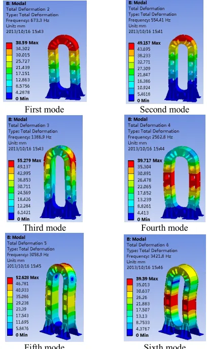
3. 2. 2. Modal Analysis Results and Discussion Figure 8 is therack overall deformation, and Figure 9the third principal stress of the rack called σ3.The overall structure of the rack is under compressive stress; the compressive stress on the column between the 60-100MPa,and the coefficient of column hom together surfaces can be up to 0.4-0.5.So, the hom together surfaces can produce enormous friction, which ensure the security and integrity of the overall rack structure.Figure 10 is the first six order modal analysis results of the overall rack structure.
(a) front view
(b) lateral view
Figure 7. Loading rack finite elementmodel diagram
Figure 8. Rack overall deformation
Figure 9. Third principal stress of the rack
First mode Second mode
Third mode Fourth mode
Fifth mode Sixth mode
Figure 10. First six order modal analysis resultsof the overall
rack structure
TABLE 1. Six order modal results
Order
number frequency/Hz Resonance deformation/mm Maximum Deformation form
1 554.41 49.157 front and rear swing
2 673.3 38.59 Left and right swing
3 1386.9 55.279 twisting motion
4 2562.8 39.717 left and right stretching
5 3058.9 52.628 twisting motion front and rear
6 3421.8 39.39 twisting motion left and right
maximumrack deformation is relatively small.There are hydraulic cylinders and workbench in the rack, whichhave inhibitory effect on the deformation of the rack, so the actual deformation is much less than this value.
4. NUMERICAL ANALYSIS OF HOM TOGETHER
STRUCTURE RACK
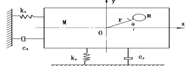
4. 1. Hom Together Structure Rack Model Hom together structure rack is made of top and bottom arch, column, transition plate and wire, which needs high installment precision when it is assembled. Due to improper installation and loading, when the rack is working, there will be eccentric loading, which has a significant impact on the rack. Therefore,the paper construct the mathematical model of hom together structure rack shown as in Figure 11.Obtain the motion
equation based on the Lagrange
principle[19]expressedasfollows:
2 2
1 1
W = m s in cos
2 t 2
2 2 2
1 1 1
2 2 2
d x rd m dy rd
d dt dt dt
d x d y d
M M J
d t d t dt
j j j j
j
æ - ö + æ + ö
ç ÷ ç ÷
è ø è ø
æ ö æ ö æ ö
+ ç ÷ + ç ÷ + ç ÷
è ø è ø è ø
(4)
1 2 1 2
2 2
U = kx + ky -Tj (5)
2 2 2
1 1 1
2 2 2
dx dy d
D c c c
dt dt dt
j j
æ ö æ ö æ ö
= ç ÷ + ç ÷ + +ç ÷
è ø è ø è ø (6)
where, W is the vibration system kinetic energy, U the system potential energy, D the energy dissipation function;, x, ythe vibration substrate horizontal and vertical displacements,,and φeccentric blocks of the rotation angle. M, m, J, r represent the vibrating, substrate mass, eccentric mass, inertia and eccentric distance, respectively. k, c and cφ are supporting
stiffness coefficient,damping, and rotary movement damping; T is the input torque of the motor[19].Obtain the following equations by Lagrange equations[20]:
( )
i
i i i i
d W W U D
Q t
dt q q q q
æ¶ ö- ¶ + ¶ + ¶ =
ç ¶ ÷ ¶ ¶ 
è & ø & (7)
(M m)d x22 kx cdx mr d22 sin d 2cos
dt dt
dt dt
j j j j
æ æ ö ö
ç ÷
+ + + = + ç ÷
ç è ø ÷
è ø (8)
(M m)d y22 ky cdy m r d 2sin d22cos
dt dt
dt dt
j j j j
ææ ö ö
ç ÷
+ + + = ç ÷
-çè ø ÷
è ø (9)
(
2)
2 2 2sin cos
2 2 2
d d x d y d
J m r mr m r c T
dt
dt dt dt
j j j j
j
+ - + + = (10)
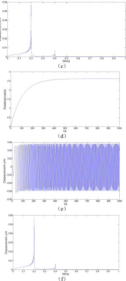
4. 2. Properties of Hom Together Structure Rack According to Equations (8)-(10), confirm the initial condition: M=32500kg, m=3000kg, r=0.8m, J=50000 kg·m2, k=3000N/m, c=60000N·s/m, c
φ=1000 N·s/m, T=2000N·m, M=325000kg. Then, obtain the displacement, velocity and displacement response spectrum of the system by numerical simulation shown in Figure 12. From Figure 12, it is known that the rack vibration characteristics of horizontal and vertical direction are approximate, and the rack resonance frequency is 201Hz. When in theresonance, the amplitude of rack is about 60mm. From (a) and (d), it is known that the maximum speed of eccentric block is about 2.63rad/s, which is far less than the rated speed, thus it is indicated that the hom together structuresatisfies the design requirements. Numerical simulation results is consistent with modal analysis results, maximum deformation of rack is slightly larger than the modal analysis, while resonant frequency is lower than the resonant frequency of the modal analysis. It is known that natural frequency of anobjectis inversely proportional to quality. Through analysis, finite element model natural frequency is larger than mathematical model because of considering the weight of the rack and the eccentric load in the numerical simulation analysis.The results verify thatthe prestressed hom together structure is reasonable.
Figure 11. Hom together structure rack mathematical model
(a)
(c)
(d)
(e)
(f)
Figure 12. Hom toghter rack system response and resonance
spectrum
5. CONLUSION
(1) Establish the heavy load rack 3D model on the basis of studying the principal of the split-hom together structure. Then analyze the vibration characteristics of heavy load rack in the prestress state and working state. (2)In the prestress state, modal analysis has been done for the rack. The minimumr esonance frequency is 554.41Hz, while the maximum deformation is 56mm. The two indexes satisfy the demands, which shows each part can maintain enough stress and generate sufficient friction toensure the structural integrity of the whole
rack.
(3) In the working state, the results of modal analysis couldnot verify the reliability of the rack because of the eccentric load, so the paper establish the mathematical model and numerical simulation have been conducted. The resonance frequency is 201Hz and the amplitude of rack is about 60mm. The two indexes satisfy the requirement, too. At the same time, the amplitudes in two states are approximate, but the frequency in the working state is smaller than the other.
Whether in the prestress state or in the working state, the vibration characteristics of heavy load rack can satisfy the requirement, so the reliability of the rack can be verified.
6. REFERENCES
1. Zhang, W.W., Wang, X.S., Yuan, S.J. and Wang, Z.R., "Design and manufacturing of cylinder-beam integrated hydraulic press",
Applied Mechanics and Materials, Vol. 397, (2013), 157-161. 2. Yongnian, Y., Junbin, P. and Feng, L., "The research and
application of pre-stressed bumpy ridges joining", in 40th CIRP International Seminar on Manufacturing Systems. Liverpool, England, (2007).
3. Peng J. B., " Integrity analysis of bumpy-ridge beam in the pre-stressed wire winded framework", Chinese Journal of Mechanical Engineering, Vol. 44, No. 12, (2008), 308-313. 4. Zhang H., "Analysis and simulation on the bumpy-ridge
structure of heavy equipment", Journal of Engineering Manufacture, Vol. 224, No. 6, (2010), 971-980.
5. Zhang H. R., "Study on influence of some factors on bumpy-ridge structure applied to heavy equipment", China Mechanical Engeering, Vol. 20, No. 23, (2009), 308-313.
6. Zhang, H., Yan, Y., Zhang, R. and Lin, F., "Analysis of the reliability of the dissected frame of heavy equipment", Tsinghua Science & Technology, Vol. 15, No. 5, (2010), 526-533. 7. Liu, H., Yan, Y., Zeng, P. and Lin, F., "Pillar and arched girder
totally bumpy ridge joining frame with steel wire wound", Jixie Gongcheng Xuebao(Chinese Journal of Mechanical Engineering), Vol. 47, No. 4, (2011), 82-87.
8. HuangZ.C., "Modal analysis of 32.8mn energy-saving automatic hydraulic press", Energy Education Science and Technology Part A: Energy Science and Research, Vol. 31, No. 1, (2013), 82-87.
9. Lv, D.Q., "Finite element static analysis of yp2080 automatic hydraulic press", in Applied Mechanics and Materials, Trans Tech Publ. Vol. 556, (2014), 1046-1049.
10. Yamapi, R. and Woafo, P., "Dynamics and synchronization of coupled self-sustained electromechanical devices", Journal of Sound and Vibration, Vol. 285, No. 4, (2005), 1151-1170. 11. Han Q. K., "Frequency capture simulation and experiment of a
rotor system with elastic supports", Journal of Vibrate and Shock, Vol. 27, No. S, (2008), 63-66.
12. Besanjideh, M. and Mahanib, M.F., "Nonlinear and non-stationary vibration analysis for mechanical fault detection by using emd-fft method", International Journal of Engineering-Transactions C: Aspects, Vol. 25, (2012), 363.
14. A. Naderi., " Element free galerkin method for static analysis of thin micro/nanoscale plates based on the nonlocal plate theory",International Journal of Engineering-Transactions C: Aspects, Vol. 26, No. 7, (2013), 795-806.
15. Junbin, P., Yongnian, Y. and Renji, Z., "Principle and application of pre-stressed bumpy-ridge in field of heavy mechanism",
Chinese Journal of Mechanical Engineering, Vol. 44, No. 6, (2008), 107-113.
16. Timoshenko, S., Goodier, J. and Abramson, H.N., "Theory of elasticity", Journal of Applied Mechanics, Vol. 37, (1970). 17. Tabor, D., The hardness of metals, 1951. 2000, Clarendon Press,
Oxford.
18. PENG, J., YAN, Y., ZHANG, R., LIN, F. and WU, R., "Pre-stressed bumpy ridge joining method for mechanical structures [j]", Journal of Tsinghua University (Science and Technology), Vol. 8, (2007),1274-1277.
19. Zhang, L.-A. and Wu, J.-Z., "Frequency capture characteristics in wind blade fatigue loading process", Journal of Sichuan University: Engineering Science Edition, Vol. 43, No. 6, (2011), 248-252.
20. Hand, L.N. and Finch, J.D., "Analytical mechanics, Cambridge University Press, (1998).
Vibration Characteristics of Heavy Load Rack with Split-hom together Structure
B. Li, L. Hou, R.Q. Mou, Y.Q. Wei
School of Manufacturing Science and Engineering, Sichuan University, Chengdu, China
P A P E R I N F O
Paper history:
Received 28 June 2014
Received in revised form 21 September 2014 Accepted 13 November 2014
Keywords: Fault detection Thau Observer Nonlinear Force
Micro-Parallel Plate Capacitor Noise And Uncertainty
ﺪﯿﮑﭼ
ﺎﺳﮏﯾمﻮﻫﻢﯿﺴﻘﺗﻢﻫﺎﺑرﺎﺘﺧﺎﺳ
هز ي ﯽﺴﻔﻗ ﻦﯿﮕﻨﺳ ﺪﯾﺪﺟ ﺖﺳا ﻪﮐ
ﺪﯿﯾﺎﺗﻪﺑزﺎﯿﻧنآرﺎﺒﺘﻋا
دراد
.
،ﻪﻟﺎﻘﻣﻦﯾارد
ﻖﯾﺮﻃزا
مﻮﻫﻞﺻاﻞﯿﻠﺤﺗوﻪﯾﺰﺠﺗ
-،سﺎﻤﺗﮏﯿﻧﺎﮑﻣوﮏﯿﻧﻮﯿﺑﺮﻈﻨﻣزالﺎﺼﺗا
لﺪﻣ
ﻪﺴﻔﻗﯽﺿﺎﯾرودوﺪﺤﻣنﺎﻤﻟا
ﺖﺳاهﺪﺷﻪﯿﻬﺗ
.
رددوﺪﺤﻣنﺎﻤﻟالﺪﻣياﺮﺑلادﻮﻣﺰﯿﻟﺎﻧآ
ﺖﻟﺎﺣ ﺶﯿﭘ هﺪﯿﻨﺗ
ﺖﺳاهﺪﺷمﺎﺠﻧا
ﺞﯾﺎﺘﻧﻪﮐ،
نآ
نﺎﻨﯿﻤﻃاﺖﯿﻠﺑﺎﻗﻪﮐ
ارﻪﺴﻔﻗ
ﯽﻣنﺎﺸﻧ
ﺪﻫد
دﻮﺷﯽﻣمﺎﺠﻧاندﺮﮐرادﻪﻧاﺪﻧدزا
.
ردرﺎﺑﻦﯿﻟواياﺮﺑﻪﺴﻔﻗزاﯽﺿﺎﯾرلﺪﻣﻪﺑيدﺪﻋيزﺎﺳﻪﯿﺒﺷﻪﮐﯽﻟﺎﺣرد
ﺖﻟﺎﺣ رﺎﮐ
هدﺎﻔﺘﺳا
،ﺖﺳاهﺪﺷ
ﯽﻣنﺎﺸﻧﺞﯾﺎﺘﻧ
ًﺎﺒﯾﺮﻘﺗشورودردﻞﮑﺷﺮﯿﯿﻐﺗﻪﮐﺪﻫد
ﺖﺳابﻮﻠﻄﻣﺪﺣردونﺎﺴﮑﯾ
.
زا،لﺎﺣﻦﯿﻤﻫرد
ﺲﻧﺎﮐﺮﻓﻞﻗاﺪﺣﻖﯾﺮﻃ
، ﻪﺠﯿﺘﻧ ي
لادﻮﻣﺰﯿﻟﺎﻧآ
ﺎﺑ ﻪﺠﯿﺘﻧ ي
يدﺪﻋيزﺎﺳﻪﯿﺒﺷ
توﺎﻔﺘﻣ
ردﺲﻧﺎﮐﺮﻓ،ﺖﺳا
ﺮﻫ ود ﺖﻟﺎﺣ
زاﺮﺗﻻﺎﺑ
ﺖﺳارﺎﮐﺲﻧﺎﮐﺮﻓ
.
نﺎﻨﯿﻤﻃاﺖﯿﻠﺑﺎﻗ،ﻦﯾاﺮﺑﺎﻨﺑ
ﯽﻣﺪﯿﯾﺎﺗشورﻦﯾاﻪﺑ
دﻮﺷ
.
![Figure 2. Cylinder and flat contact force planar graph[15]](https://thumb-us.123doks.com/thumbv2/123dok_us/228957.2017459/2.595.315.543.645.740/figure-cylinder-flat-contact-force-planar-graph.webp)
![Figure 3. Schematic diagram of different multimodal hom structure [18]](https://thumb-us.123doks.com/thumbv2/123dok_us/228957.2017459/3.595.123.217.106.304/figure-schematic-diagram-of-different-multimodal-hom-structure.webp)