Design of Measurement Memory System Based on
MEMS Acceleration Sensor
https://doi.org/10.3991/ijoe.v14i09.8689
Lei Xu, Liqing Fang!!", Xu Li, Ruikun Huo, Deqing Guo, Ziyuan Qi Mechanical Engineering College, Shijiazhuang, China
Abstract—With the rapid development of MEMS technology, MEMS ac-celeration sensors have been used more and more widely due to their unique advantages. Taking MEMS acceleration sensor as the core device, a measure-ment memory system was designed. The system mainly included acceleration detection module, acceleration memory module and control display module, which could realize real-time acceleration measurement and memory, and up-loaded the stored data to the computer. The vibration test was used to detect the performance of the system. Result showed that the system could achieve the de-sired effect, and realize real-time acceleration measurement and memory within the allowable error range. The system possessed strong resistance to high overload capacity, which could still work normally under the condition of the maximum overload of at least 100g.
Keywords—MEMS technology; MEMS acceleration sensor; measurement-memory system
1
Introduction
successfully developed in many aspects, and the maximum overload could reach 200000 g. Using this accelerometer could achieve the penetration depth control, which would be greatly promoted in drilling munitions [8].Although application ran-ge of the acceleration sensor was expanding, due to the limitation of the technical level, practical application which used MEMS acceleration sensor as the core design still remains low [9-10].
Acceleration, velocity and displacement were important indicators of the motion characteristics of objects. Obtaining these signals was of great significance for evalu-ating the functional properties of an object and grasping the state of the moving object at all times [11-12] . Compared with the acceleration signal, displacement signal and velocity signal were more difficult to obtain accurately in engineering practice [13-16], but the mathematical calculus relationship between acceleration, velocity, and displacement was also relatively clear. It was possible to indirectly obtain displace-ment and velocity of an object by using the calculus relationship between accelerati-on, velocity, and displacement. Using MEMS acceleration sensor to measure the motion characteristics of an object had unique advantages.
2
Overall Design of the Measurement Memory System
2.1 Overall Design of the Hardware Circuit
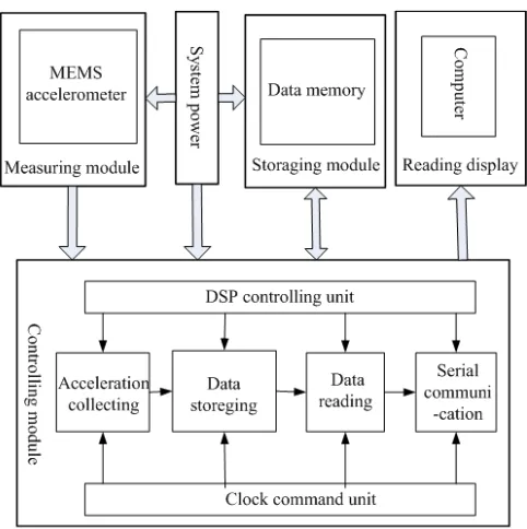
In the measurement memory system, the functions to be implemented include ac-celeration signal detection, acac-celeration signal storage, and acac-celeration signal upload. In order to realize the corresponding functions, the system is divided into three mo-dules: acceleration detection module, acceleration storage module, and control display module. The overall block diagram of the system is shown in figure 1.
Fig. 1. Overall block diagram of the measurement memory system
2.2 Overall Design of Software
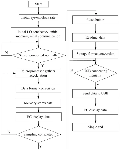
Objects controlled by the measurement memory system designed with MEMS ac-celeration sensor as the core include I2C data acquisition, SPI data storage, and SCI data transmission. The software flow chart is shown in figure 2. When the system is powered on, the microprocessor first initializes each module, which mainly includes the initialization of the microprocessor, memory, sensors, and communication unit. After the initialization, the acceleration sensor starts to detect the acceleration of the object, and sends the data to the microprocessor. The microprocessor checks the connection status of the acceleration sensor. When the connection is normal, the ac-celerometer signal supplied by the sensor is received, and the format is converted. The data will be collected accordingly. Acceleration data is sequentially stored in a ferroelectric memory. The vibration module is directly connected to the computer while the vibration tester is in vibration. When the microprocessor stores data, the data measured by the sensor is also displayed in the computer. After a period of vibra-tion, the process is judged. Whether the sampling is completed, press the reset button after the sampling is completed. At this time, the acceleration data of the storage module will be uploaded to the computer in a fixed format. After transporting succes-sfully, the power is turned off and the measurement storage system stops working.
The microprocessor uses DSP which possesses advantage of digital processing. In order to make full use of digital processing capabilities of DSP, maximize the acquisi-tion frequency of the acceleraacquisi-tion sensor in the vibraacquisi-tion process, meet the require-ments of real-time measurement and storage in the measurement memory, the system adopts data stream processing to collect and process acceleration signals. After the completion of an acquisition, the acceleration data is sequentially stored immediately. it needs to be ensured that the acceleration sensor will not generate acceleration data before completing storage. Since the data stream processing method can be stored and implemented within the sampling period of the sensor, the system delay can be mini-mized, so acceleration sensor can reach the maximum acquisition frequency, which is conductive to improving the measurement accuracy .
2.3 Error Evaluation Criteria
For the acquired acceleration signal, MATLAB simulation can be used to fit the waveform of the vibration acceleration change. Through comparing measuring curve with the waveform diagram of the vibration test bench, it can be seen intuitively that the measured acceleration of the storage system coincides with the output acceleration of the test stand. However, in order to quantitatively analyze the measurement results, there must be corresponding indicators for error evaluation. In this paper, the perfor-mance of the measurement storage system is evaluated by using three error evaluation parameters, namely the sum-squared error, the average maximum relative error, and the average peak error.
To evaluate two waveforms, we must first examine the overall effect of different waveforms, that is, to evaluate the energy difference of the waveforms. Therefore, the sum of squared error is introduced to describe the energy difference between the out-put signal of the shaking table and the actual measurement signal.
(1) In the formula, b(i) represents the actually measured acceleration signal, a(i) re-presents the shaking table output signal, and N rere-presents the sampling point [16].
(2)
The average peak error is the average of the errors of the positive and negative peaks of the acceleration time b(t) with respect to the positive and negative peaks of the ac (t) of the vibration table.
(3)
3
Design of Hardware Circuit
3.1 Design of Acceleration Measurement Module Circuit
INT INT
SDA SCL SDA SCL SDA SCL
Master unit Slave unit
I2C bus
SDA
SCL VCC
Pull-up resister Pull-up resister
Slave unit
Fig. 3. Circuit schematic of acceleration measurement module
3.2 Design of Acceleration Memory Module Circuit
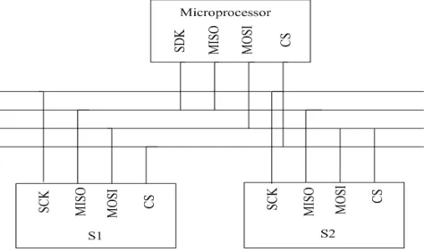
The memory module utilizes the ferroelectric memory FM25V20A, which is recent introduction of a non-volatile memory that combines low power consumption and high performance in Ramtron. The stored data is not lost after power down, which not only overcomes the shortcomings of long writing time of EEPROM. and low erasure of FLASH, but also costs much lower than other non-volatile SRAMs. The circuit schematic is shown in figure 4. The processor and ferroelectric memory are connected by using a SPI (Serial Peripheral Interface) bus, in which a master device is connected to a plurality of slave devices. A four-wire communication method is used, which includes: SCLK clock, CS slave device Select, MISO master input slave output, and MOSI master output slave input. The controller determines the ferroelectric memory using the CS pin, writes read data commands to the MEMS acceleration sensor through the MOSI, and reads the output acceleration of the MEMS acceleration sen-sor from the MISO port, and provides an external clock signal for the MEMS accele-ration sensor through the SCLK port.
3.3 Design of Control Display Module Circuit
The control display module includes a storage unit and a communication unit, completes real-time reading and storage of the acceleration, and uses the serial com-munication circuit to upload the data to the computer. This module uses a micropro-cessor DSP (Digital Signal Promicropro-cessor) which is capable of high-speed digital signal processing operations. DSP adopts the Harvard structure, has independent program space and data space, whose program space and data space access simultaneously through an independent data bus. Built-in high-speed multipliers and enhanced multi-stage pipelines enable high-speed data processing capabilities. The DSP also provides highly specialized instruction sets that increase the speed of operation. The charac-teristics of the DSP greatly increase its computing power and processing power, so that it can well meet the requirements for fast, accurate, real-time processing and control of signals.
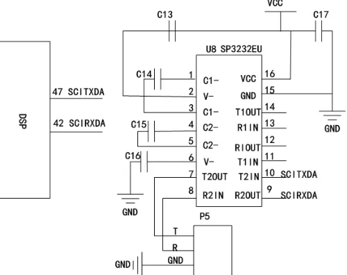
The communication unit realizes the communication between system and computer which uploads the acceleration data stored in the ferroelectric memory into the com-puter. As is shown in Figure 5, DSP uses a serial interface circuit to achieve commu-nication with the host computer. This commucommu-nication method has less data lines and can save costs in long-distance communication. At the same time, SCITXDA and SCIRXDA realize the data sending and receiving respectively, which make transmis-sion speed faster. The serial interface circuit design is implemented using the com-mon RS-232 (ANSI/EIA-232 standard) serial connection standard. The hardware design directly connects the serial port to the USB circuit. No matter encoding mode or the level conversion, it can meet the requirements of using. Therefore, there is no need for excessive support for software programming, and the processing speed of the processor is increased.
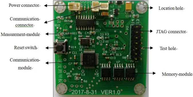
The circuit board of the system is shown in figure 6, power connector provides vol-tage for the whole system through connecting external power; communication connector realizes real-time reading display and storage display of acceleration data. In order to ensure the normal operation of the circuit system, measure the working status of the circuit board accurately, test holes are provided in the circuit board to facilitate the detection of the output signal. Two data storage display, the real-time acceleration measurement data unconverted and the data converted from ferroelectric memory. When the two pieces of data are consistent, it indicates that the measure-ment memory system is working properly .Then the data uploaded to the computer is analyzed. , and the measurement accuracy of the measurement storage system is tested.
Fig. 6. Printed circuit board
4
Design of Vibration Test
the test of high overload resistance, then set the vibration test stand outputs measurab-le accemeasurab-leration data. Through observing the LED lights flicker, observing data display interface data characteristics, and outputting upload acceleration data, analyzing the data output curve, the working status of the measurement system was determined.
Fig. 7. Design of vibration test
5
Results and Analysis
There were two groups of data uploaded to the computer. One group was real-time measurement and uploading data, the storage format of which was not converted. The other group was the data that was stored in ferroelectric memory. Both sets of data were presented as binary values. The form of the complement code was uploaded. The original data was shown in Table 1, and the second set of acceleration data was processed using MATLAB.
Table 1. Results of vibration test Real-time measurement data
original value Real-time measurement data actual value Original data in storage system
0xb6 0x07 0b67H 0b67H
0xca 0x0e 0caeH 0caeH
0xa8 0x07 0a87H 0a87H
0xb7 0x0c 0b7cH 0b7cH
0xc8 0x0e 0c8eH 0c8eH
0xe5 0x08 0e58H 0e58H
0xec 0x0a 0ecaH 0ecaH
0xc6 0x07 0c67H 0c67H
0xb6 0x0a 0b6aH 0b6aH
!
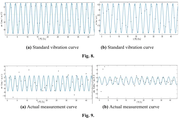
(a) Standard vibration curve (b) Standard vibration curve Fig. 8.
(a) Actual measurement curve (b) Actual measurement curve Fig. 9.
The obtained data were fitted by using MATLAB curve fitting tool.The fitted cur-ves obey respectively a=-3.061-2.092!cos(i!2.504)-3.494!sin(i!2.504), a=-6.545+0.9701!cos(i!2.086)+ 0.48!sin(i!2.086). Due to the influence of gravity ac-celeration during the vibration test, the acac-celeration of gravity should be added to the fitting function. The function after adding gravity acceleration was shown in Table 2.
Table 2. Comparison table of output function and measurement function of vibration test stand
Test stand output
function Function added gravity acceleration Measurement function
a=6.8-2!cos(t!
2.5)-3.5!sin(t!2.5) a=-3-23.5!!sin(tcos(t!!2.5) 2.5)- a=-3.061-2.092sin(i!cos(i!2.504) !2.504)-3.494!
a=3.3+cos(t!2)+0.2!sin(t
!2) a=-6.5+cos(t!2)+0.2!sin (t!2) a=-6.545+0.9701sin(i!!cos(i2.086) !2.086)+0.48!
Table 3. Error Analysis of Acceleration Measurement The
sum-squared error% the average maximum relative error % the average peak error %
First vibration test 1.5 1.04 1.37
Second vibration test 2.6 2.78 0.68
!
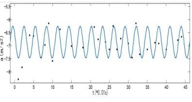
From Table 1, it could be seen that the two sets of data were identical, which indi-cated that the measurement memory system worked normally, and that acceleration measurement and storage could be performed; from the comparison of the output function and the output curve, it could be found that the measurement memory system could basically and accurately measure the variation trend of vibration test. From Table 3, it could be seen that the accuracy of the acceleration measurement of the acceleration measurement storage system was high, and data support could be provi-ded for speed calculation and displacement calculation within the allowable error range, which could meet the needs of the actual project. When carrying out the anti-overload capability test of the vibration test stand, the maximum acceleration of the vibration test stand was adjusted to 50g, 80g, 100g for two minutes, followed by a=3+0.4!cos(t!2)-0.5! sin(t!2). The test results of the measurement memory system were shown in FIG. 10.
Fig. 10. Measuring Vibration Curve
From the vibration curve and the LED flashing status, it could be judged that the measurement memory system could still work normally, and system could resist a high overload.
6
Conclusion
ability to resist high overload. Under the condition of at least 100g, the measurement memory system was basically free from damage and could still work normally. It could be used under high-speed impact environmental conditions. The performance of the MEMS acceleration sensor in the measurement memory system was stable. By comparing with the actual output curve of the vibration experiment, it was found that the system could basically and accurately measure the vibration acceleration and meet the requirements of engineering applications within the allowable error range. It could provide reliable data for the calculation of velocity and displacement. But the system was affected by installation errors, ambient temperature, and sensor zero drift during the test . Of course, these paramaters can all be further processed. For example, the installation errors can be reduced by optimizing the processing technology,;the tem-perature control test can be used to obtain the influence law of temtem-perature on the system, and the zero-drift of the system can be determined by the turntable test. Through various measures, the system can be further optimized.
7
References
[1]Chakraborty A, Gupta B.(2016) Development of compact 180° phase shifters based on MEMS technology [J]. Sensors & Actuators A Physical, 247:187-198. https://doi.org/10.1016/j.sna.2016.05.046
[2]WANG J,JIANG X J,ZHANG L,et al.(2015). Design and fabrication of ener-getic superlattice like-PTFE/Al with superior performance and application in functional micro-initiator [J] Nano Energy, 12: 597−605.https://doi.org/10.1016/j.nanoen.2014.12. 016
[3]Xu R, Ghou S, Li WJ.(2012). MEMS accelerometer based nonspecific-user hand gesture recognition [J].IEEE Sensors Journal,12(5):1166-1176. https://doi.org/10.1109/JSEN.201 1.2166953
[4]Merz, P.;Reimer, K.;Weiss, M. et.al.,Combined MEMS inertial sensors for IMU applica-tions, 2010 IEEE 23rd International Conference on Micro-Electro-Mechanical Systems (MEMS), Jan 24-28, 2010, Wanchai, Hong Kong, pp:488-491 .
[5]Peter S, Hubert G.(2012). State estimation on flexible robots using accelerometers and an-gular rate sensors [J]. Mechatronics,22(8):1043-1049. https://doi.org/10.1016/j.mechatroni cs.2012.08.009
[6]Han Ying Dang, Li Zhe.(2015). Data Acquisition and Preprocessing of MEMS Accelerati-on Sensors [J]. InstrumentatiAccelerati-on Technology and Sensors,2:16-19.
[7]Wen Feng, Shi Yunbo, Zhou Zhen, et al.(2013). High-g-value accelerometer based on MEMS and its application in projectile penetrating double-layer steel target test[J]. Journal of Vibration and Shock, 32(19):165-169.
[8]Beravs T, Podobnik J, Munih M.(2012). Three axial accelerometer calibration using kal-man filter covariance matrix for online estimation of optimal sensor orientation[J].IEEE Transactions on Instrumentation and Measurement,61(9):2501-2511. https://doi.org/10.11 09/TIM.2012.2187360
[9]WANG Dai-hua,Yuan Gang. (2011). A six-degree-of-freedom acceleration sensing meth-od based on six coplanar single-axis accelerometer[J].IEEE Transactions on Instrumenta-tion and Measurement,60(4):1433-1442. https://doi.org/10.1109/TIM.2010.2083331 [10]Lin P C, Lu .T C , Tsai C H,et al.(2012). Design and implementation of a nine-axis
[11]Wan Zhen, Cui Feng, Zhang Weiping, et al. Design of proof mass and system-level simu-lation of a micromachined electrostatically suspended accelerometer[C].2011 Internation-al Conference on Advanced Design and Manufacturing Engineering Guangzhou, China. pp:1631-1634.
[12]Dongjun Hyun, Minsu Jegal. Compact Self-contained Navigation System with MEMS In-ertial Sensor and Optical Navigation Sensor for 3-D Pipeline mapping[C]. International Conference on Intelligent Robots and Systems,2010,Taibei,pp:1488-1493.
[13]Xu R Z, Zhou S L, Li W J. (2012). MEMS Accelerometer Based Nonspecific-User Hand Gesture Recognition[J]. IEEE Sensors Journal,12(5):1166-1173. https://doi.org/10.1109/ JSEN.2011.2166953
[14]Young D J, Zurcher M A, Semaan M, et al.(2012). MEMS Capacitive Accelerometer-Based Middle Ear Microphone[JJ. IEEE Transactions on Biomedical Engineer-ing,59(12):3283-3292. https://doi.org/10.1109/TBME.2012.2195782
[15]Li Jie, Zhao Wei, Liu Jun, et al.(2013). Semi-strapdown MEMS inertial measurement de-vice for high-spinning ammunition flight attitude measurement[J]. Acta Metallurgica Sini-ca, 34(11):1398-1403.
[16]Wen Guangrui ,Li Yang, Liao Yuhe,et al. (2013). Faulty rotor system vibration acceler-ation signal integracceler-ation method based on precise informacceler-ation reconstruction [J] . Journal of Mechanical Engineering ,49(8):1-9. https://doi.org/10.3901/JME.2013.08.001
8
Authors
Lei Xu (First author)is a master student in Mechanical Engineering College, Shi-jiazhuang, China. His main research direction is mechanical testing technology. ( Email:[email protected]).
Liqing Fang is a professor in Mechanical Engineering College, Shijiazhuang, China. His main research direction is the mechanical performance testing and fault diagnosis technology. (Email:[email protected]).
Xu Li is a master student in Mechanical Engineering College, Shijiazhuang, Chi-na. His main research direction is mechanical testing technology.
Ruikun Huo is a master student in Mechanical Engineering College, Shijiazhuang, China. His main research direction is mechanical testing technology.
Deqing Guo is an associate professor in Mechanical Engineering College, Shijia-zhuang, China. His main research direction is mechanical fault prediction technolo-gy.
Ziyuan Qi is an associate professor in Mechanical Engineering College, Shijia-zhuang, China. His main research direction is mechanical fault prediction technolo-gy.