Available Online at www.ijpret.com 153
INTERNATIONAL JOURNAL OF PURE AND
APPLIED RESEARCH IN ENGINEERING AND
TECHNOLOGY
A PATH FOR HORIZING YOUR INNOVATIVE WORK
DESIGN AND ANALYSIS OF HORIZONTAL PRESSURE VESSEL FOR VACUUM
SYSTEM DRAIN COLLECTION RECEIVER
PROF. PRASAD L. MANE1, PROF. V. MURALI MOHAN 2 1. Assistant professor, Automobile, RMCET Ratnagiri, Maharashtra, India
2. Associate Professor, Mechanical, FAMT Ratnagiri, Maharashtra, India
Accepted Date: 15/03/2016; Published Date: 01/05/2016
\
Abstract: The knowledge of process equipment design or Pressure Vessel design is an important prerequisite for the development of any processing industries, such as oil & gas, Chemical Processing Industries, Pharmaceutical, since it governs the shape and size of the plant.in this project work emphasis is given on mechanical aspect of process equipment design i.e. strength and rigidity consideration, for the smooth functioning and operation of equipment. In a refinery or in process industry for some process purpose vacuum is required to remove the air inside the piping and main vessel. That air may contain moisture, chemical vapors and steams etc. It is also a very corrosive environment. All of this corrosive air will get condensed and that condensate need to store in an ancillary pressure vessel as a collection receiver for an oil refinery or process industry. The proposed work focuses on design and analysis of horizontal pressure vessel for Vacuum system drain collection receiver based on (ASME) Boiler and Pressure Vessel Code, Section VIII, Division 1. As per the customer requirement, the pressure vessel will be designed for a capacity of 0.5 m3. The vessel is required to contain an internal working pressure of 0.815 kg/cm2 with Temperature is 51.6 0C. In order to make this pressure vessel safe, the vessel is designed for Maximum pressure is 1.54 kg/cm2, with design temperature of the fluid is 1020C. The Theoretical results are validating with the PV elite software result as per ASME Section –VIII and Division.1.
Keywords:Vacuum system, ASME, Pressure vessel, and condensate etc….
Corresponding Author: PROF. PRASAD L. MANE
Access Online On:
www.ijpret.com
How to Cite This Article:
Prasad L. Mane, IJPRET, 2016; Volume 4 (9): 153-171
Available Online at www.ijpret.com 154 INTRODUCTION
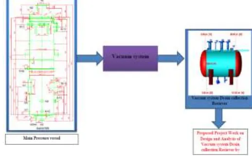
Pressure vessel is a closed cylindrical vessel for storing gaseous, liquids or solid products. The stored medium is at a particular pressure and temperature. The cylindrical vessel is closed at both ends by means of dished end, which may be hemispherical, ellipsoidal and torispherical. The pressure vessels may be horizontal or vertical. In a refinery or in process industry for some process purpose vacuum is required to remove the air inside the piping and main vessel. That air may contain moisture, chemical vapors and steams etc. It is also a very corrosive environment. All of this corrosive air will get condensed and that condensate need to store in an ancillary pressure vessel as a collection receiver for an oil refinery or process industry as shown in fig-1
The proposed work focuses on design and analysis of horizontal pressure vessel for Vacuum system drain collection receiver based on (ASME) Boiler and Pressure Vessel Code, Section VIII, Division 1. As per the customer requirement, the pressure vessel will be designed for a capacity of 0.5 m3. The vessel is required to contain an internal working pressure of 0.815 kg/cm2 with Temperature is 51.6 0C. In order to make this pressure vessel safe, the vessel is designed for Maximum pressure is 1.54 kg/cm2, with design temperature of the fluid is 1020C.
Fig -1: Layout of project work
1.1 Basic Considerations in Process Equipment Design
(a) Selection of type of vessel and its capacity required gives the service in the most satisfactory manner. Here the basic parameters under consideration are function of the vessel, nature of fluid and process, and storage or processing capacity of equipment.
Available Online at www.ijpret.com 155 (c) Appropriate Material of Construction: For the construction of equipment, appropriate material must be recommended which should be suitable for the process conditions with sufficient strength and low cost. Another important requirement of the material selected is the ability to resist the corrosion.
(d) Sufficient Strength and Rigidity of Components and Equipment: While designing equipment, various loads are to be considered; like load due to self-weight, loads from supported equipment and piping, wind and earthquakes load, impact and cyclic load which ultimately affect the strength and rigidity of equipment.
(e)Performance of Mechanism: Satisfactory performance of mechanism for smooth and reliable functioning of equipment is required.
(f) Ease of maintenance and repair: selection and positioning of the proper openings and connections gives ease in maintenance and repair or replacement.
(g) Ease of Operation and control: Equipment should be designed ergonomically for easy operation and control. The controls should be easily accessible and logically positioned.
(h) Fabrication Methods: Each fabrication method has certain advantages for particular types of equipment. The size, shape, service, and material properties of the equipment influence the selection of the reliable fabrication method.
(i) Economic Considerations: Obviously it is a major constraint on any engineering design: plant must make profit within its constraints; the cost of material, mechanism and fabrication must be as low as possible.
(j) Safety Requirements: all safety measures must be taken while designing equipment.
1.2 Materials of Construction for Processing Equipment’s
Available Online at www.ijpret.com 156
The materials commonly used in process vessel construction can be grouped as follows:
1. Ferrous Materials: carbon, low alloy, high alloy and stainless steels etc.
2. Non-Ferrous Materials: Aluminum, copper, nickel and their alloy etc.
3. Non-Metallic Materials: Plastics, rubber, glass, graphite etc.
1.3 Limitations of Pressure Vessel
Fatigue occurs when a material is subjected to repeated loading and unloading. If the loads are above a certain threshold, microscopic cracks will begin to form at the stress concentrators such as the surface, persistent slip bands (PSBs), and grain interfaces. Round holes and smooth transitions or fillets will therefore increase the fatigue strength of the structure. Pressure vessels are held together against the gas pressure due to tensile forces within the walls of the container. The normal (tensile) stress in the walls of the container is proportional to the pressure and radius of the vessel and inversely proportional to the thickness of the walls. Therefore, pressure vessels are designed to have a thickness proportional to the radius of tank and the pressure of the tank and inversely proportional to the maximum allowed normal stress of the particular material used in the walls of the container.
A fracture is the separation of an object or material into two or more pieces under the action of stress. The fracture of a solid usually occurs due to the development of certain displacement discontinuity surfaces within the solid. If a displacement develops perpendicular to the surface of displacement, it is called a normal tensile crack or simply a crack; if a displacement develops tangentially to the surface of displacement, it is called a shear crack, slip band, or dislocation. Fracture strength or breaking strength is the stress when a specimen fails or fractures.
2. Aim and objectives behind present research work
Aim of proposed work is to design new horizontal pressure vessel For Vacuum system Drain Collection Receiver as per ASME div VIII section1 and analyzing with PV elite software results. The main objectives of proposed work is to analyze the design of a horizontal pressure vessel For Vacuum system Drain Collection Receiver as per customer requirement based on ASME code section VIII Divison.1. According to that following are the objectives to be discussed. To understand the industrial operating parameters by industrial visit.
Available Online at www.ijpret.com 157
To understand the reasons behind the defect occurred in the horizontal pressure vessel. • To plan for design of horizontal pressure vessel In Vacuum system Drain Collection Receiver based on ASME code section VIII Divison.1.
To prepare a model for analysis purpose using PV Elite Software techniques.
To prepare design calculation to overcome possible defects in horizontal pressure vessel.
To compare theoretical results with the results of PV elite software.
To check design consistency and suggest final design for fabrication based on the analysis carried out.
2.1 Definition of the problem:
In a refinery or in industry for some process purpose vacuum is required to remove the air inside the piping and main vessel. This vacuum is created with the help of vacuum system. That air may contain moisture, chemical vapors and steams etc. It is also a very corrosive environment. As per the client’s requirement, all of this corrosive air will get condense and that condensate need to store in an ancillary pressure vessel as a collection receiver for an oil refinery or process industry.
In order to make horizontal pressure vessel For Vacuum system Drain Collection Receiver we are using the ASME code section VIII Div.1 and analyzing the same with the results we are getting with the help of PV Ellite software. Also tackling various defect arising in the pressure vessel.
Thus problem can be defined as “Design of horizontal pressure vessel For Vacuum system Drain Collection Receiver as per customer requirement and overcoming defects arising in horizontal pressure vessel”
3. Manual Calculations
Design pressure including static head:
Static Head =
=
=433.705 Kg/ = 0.043 Kg/cm²
Therefore,
Available Online at www.ijpret.com 158
= 1.54 +0.043
= 1.583 Kgf/cm²
3.1 Cylindrical Shell Thickness for Internal Design Pressure as Per UG-27(c)
Fig -2: Cylindrical shell 1] Circumferential Stress (Longitudinal Joints) as per UG 27 (c):
Minimum required thickness
=
= 0.361 mm
2] Longitudinal Stress (Circumferential Joints) as per UG 27 (c):
Minimum required thickness
=
=0.212 mm
But, As per UG-16(b), Minimum required thickness shall be>3/32 inch
i.e., = 0.094 inch
=2.500mm
Therefore
Cylindrical Shell Thickness =Governing thickness + corrosion allowance
=2.500+3
SE P
PR t 6 . 0
SE P
Available Online at www.ijpret.com 159
=5.500~6mm
3.2 Cylindrical Shell Thickness for External Design Pressure as Per UG-28(c):
Fig -3: Cylindrical shell From Fig. G Subpart 3 of section II part D,
Factor A= 0.0002272
From Fig. CS-2 Subpart 3 of section II part D, Factor B= 22.71
Maximum Allowable external working Pressure (Pa):
Pa= 4B/3(D0/t)
=4*22.71/3*(215.6667)
=0.140402 MPa
AS Pa > P Hence Thickness Is Adequate. Design is Safe for External Pressure
3.3 Ellipsoidal Head Thickness for internal design pressure, as Per UG-32 (d)
Fig -4: Ellipsoidal head
Minimum Required Thickness of Head as Per UG-32(d)
t = 0.155∗641
(2∗138∗1)−(0.2∗0.155
SE P
PD t
2 . 0 2
Available Online at www.ijpret.com 160
t = 0.36mm
t = 0.36mm
But, As per UG-16(b), Minimum required thickness shall be>3/32 inch
i.e. , 𝑡 = 0.094 inch
=2.500mm
Therefore,
Ellipsoidal Head Thickness = Governing thickness + corrosion allowance
= 2.500+3
=5.500~6mm
Provided Head Thickness is Adequate.
3.4 Ellipsoidal Head Thickness for External design pressure, as Per UG-33(d)
Fig -5: Ellipsoidal head
Spherical Radius Factor (𝐾𝑂) =0.90
Therefore,
Outside Radius of Ellipsoid Head
(𝑅𝑂) = (𝐾𝑂*𝐷𝑂)
(𝑅𝑂) =0.90*647
Available Online at www.ijpret.com 161
Factor A = 0.125𝑅𝑂
𝑡
=582.300∗30.125
= 0.000644
From fig CS-2, Factor
B=64.380Mpa
=656.483 Kg/Cm2
Maximum Allowable external working Pressure (𝑃𝑎)
(𝑃𝑎) =𝑅𝑂𝐵 𝑡
𝑃𝑎 =582.300/364.380
𝑃𝑎 = 0.332 MPa
𝑃𝑎 = 3.38 Kg/Cm2
Hence Pa > P Hence Thickness Is Adequate.
3.5 Checking for Heat Treatment of Shell (As Per UCS-79 &UG 79):
all vessel shell sections, heads, and other pressure parts fabricated by cold forming shall be heat treated subsequently when the resulting extreme fiber elongation exceeds 5% from the supplied condition.
The extreme fiber elongation:
%Elongation = (50×𝑡)
𝑅𝑓 × (1 −
𝑅𝑓
𝑅𝑂)
= 320.500(50×6) × (1 − 320.500
𝑖𝑛𝑓𝑖𝑛𝑖𝑡𝑦)
=0.936
Available Online at www.ijpret.com 162 3.6 Checking for Heat Treatment of Dish end (As per UCS-79 &UG 79):
The extreme fiber elongation:
%Elongation =(75×𝑡)
𝑅𝑓 × (1 −
𝑅𝑓
𝑅𝑂)
Where,
Inside spherical radius of dish = K0× 𝐷𝑖
=0.9×635
=571.500mm
Inside knuckle radius of dish =0.17× 𝐷𝑖
=0.17×635
=107.950mm
Governing radius = min ( Ko× 𝐷𝑖, 0.17× 𝐷𝑖)
=107.950mm
Final Centerline mean Radius= (governing thickness + t/2)
𝑅𝑓=107.950+6/2
𝑅𝑓=111.950mm
Material designation=SA516 Gr 70
% Elongation= (75×8)
111.950× (1 −
111.950 𝑖𝑛𝑓𝑖𝑛𝑖𝑡𝑦)
=5.36
% Elongation is 5.36(exceed than 5%) therefore heat treatment check is required for Dish end.
4. PV-Ellite software Calculations
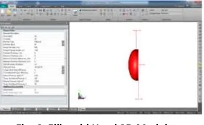
4.1 Inputs for Ellipsoid Head:
In element screen different type of head are available.
Available Online at www.ijpret.com 163
• Hemispherical • Torispherical • 2:1 Ellipsoidal • Conical Flat Head • Flanged Head.
Select the required head from it.Then put the following inputs • Dimensions • Material of construction • Straight face dimension • Finished Thickness • Nominal Thickness • Corrosion allowance • Material of construction • Condition of Material (Normalized / Not Normalized) • Design Parameters .Once we put all the values dish end will appear in screen as shown below:
Fig -6: Ellipsoid Head 3D Model
4.2 Inputs for Cylindrical Shell:
In element screen select a shell. Then put the following inputs • Diameter
• Shell Length
• Material of construction • Finished Thickness • Nominal Thickness • Corrosion allowance • Material of construction
• Condition of Material (Normalized / Not Normalized) • Design Parameters
Once we put all the values dish end will appears in screen as shown below:
Available Online at www.ijpret.com 164 4.3 Inputs for Nozzles:
Select the element on which you want to provide nozzle. Then click on the Nozzle Symbol indicated in “Detail Screen”. Once you click on nozzle symbol, below screen will appear. First select the required type of Nozzle. To select type click on the correct image of below screen. These images are of
• Set in Nozzle with RF Pad • Set in Nozzle without RF Pad • Set out Nozzle with RF Pad • Set out Nozzle without RF Pad • SRN (Self Reinforced Nozzle)
Once we select required type of nozzle then we have to put following parameters of Nozzles
• Nozzle Description • Nozzle Material • Nozzle Size
• Nozzle thickness (Nozzle Schedule) • Corrosion allowance
• Nozzle elevation / Distance from Node (Weld Line) • For Inclined Nozzle, Nozzle inclination angle. • If not inclined the click on radial nozzle. • Nozzle inside Projection
• Nozzle outside Projection
If Reinforcement element is required then put • Pad Material
• Pad outside Diameter • Pad Thickness
• Welding Details of Nozzles Nozzle Flange Details
• Flange Type (Like WNRF/SORF etc) • Flange Rating
• Flange Grade
Available Online at www.ijpret.com 165 Fig -8: Nozzles 3D Model
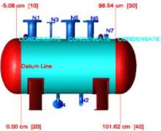
Then click on the analyze symbol which is in “Analyze” screen. Then you will get complete vessel calculations Reports.
Fig -9: Vacuum system drain collection receiver (3D-Model)
5. RESULTS AND DISCUSSION
5.1 Cylindrical Shell Design for internal Pressure:
Available Online at www.ijpret.com 166 Chart -1: Cylindrical Shell Thickness for internal Pressure
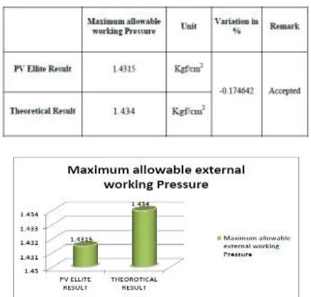
5.2 Cylindrical Shell Design for External Pressure:
Table -2 Maximum allowable working Pressure
Chart -2: Maximum allowable working Pressure
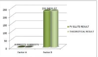
5.3 Shell Design for External Pressure:
Available Online at www.ijpret.com 167 Chart -3: Factors A and Factor B Results
5.4 Ellipsoid head Design for internal Pressure:
Table -4 Ellipsoid head thickness for internal Pressure
Chart -4: Ellipsoid head thickness for internal Pressure
5.5 Ellipsoid head Design for External Pressure:
Available Online at www.ijpret.com 168 Chart -5: Factors A and Factor B Results
5.6 Ellipsoid head Design for External Pressure:
Table -6 Maximum allowable working Pressure
Chart -6: Maximum allowable working Pressure
5.7 Ellipsoid head Design for External Pressure Results:
Available Online at www.ijpret.com 169 Chart -7: Ellipsoid head Thickness
5.8 Extreme Fiber Elongation Results:
Table -8 Extreme Fiber Elongation
Chart -8: Extreme Fiber Elongation
5.9 Hydrostatic test pressure Results:
Available Online at www.ijpret.com 170 Chart -9: Hydrostatic test pressure
3. CONCLUSIONS
A numerical design study was performed to examine the structural failure of pressure vessels exposed to internal pressure As per ASME section VIII Div.1.Also it is analyzed by PV-Ellite software the result fully complied with standard code and had been employed on practical design of pressure vessel.
The design of pressure vessel is more of a selection procedure, selection of its component rather than designing each and every component, for storage of fluid the pressure vessel is mostly used because of its simplicity, high reliability, lower maintenance and compactness. The main parameter towards the design of pressure vessel is its high pressure fluid storage. The selection of pressure vessel component is very critical, slight change in selection will lead to different pressure vessel altogether from what is aimed to be designed. It is observed that all the manufactures of pressure vessels follow the ASME design codes for designing of pressure vessel so that leaves the designer free from designing the component. This aspect of design greatly reduces the development time for a new pressure vessel. It also allows the designer the freedom to play with multiple prototypes for the pressure vessel before finalizing the decision. Selection of pressure vessel should be according to standards rather than customizing the design additional conclusion were made from project study are Low overall cost, Less time.
REFERENCES
1. J.C. Virella et all” Dynamic buckling of anchored steel tanks subjected to horizontal earthquake excitation” Journal of Constructional Steel Research 2006.
Available Online at www.ijpret.com 171
3. J. Katolickýet all “CFD analysis of coolant flow in the nuclear reactor VVER440” Applied and Computational Mechanics 2007.
4. R.C. Carbonari et all “Design of pressure vessels using shape optimization: An integrated approach” International Journal of Pressure Vessels and Piping 2011.
5. Kiran D. Parmar et all “Thermal analysis for skirt dished end joint of pressure vessel using finite element analysis approach.” International Journal of Advanced Engineering Research and Studies 2012.
6. Shaik Abdul Lathuef et all “Design and structural analysis of pressure vessel due to change of nozzle location and Shell thickness” International Journal of Advanced Engineering Research and Studies 2012.
7. Jagajyoti panda et all “Analysis and design of vertical vessel foundation” Department of Civil Engineering ,National Institute of Technology Rourkela 2013.
8. Farhad Nabhani et all” Reduction of Stresses in Cylindrical Pressure Vessels Using Finite Element Analysis” Teesside University, School of Science and Engineering2012.
9. Myung Jo Jhung “Fatigue analysis of a reactor pressure vessel for smart” nuclear engineering and technology 2011.
10. Viraj H. Barge et all “Thermal-structural analysis &optimization of pressure vessel using finite element analysis” International Journal of Advanced Engineering Research and Studies 2013.
11. Mohammed Qazam naser “Structural & Thermal Analysis of Pressure Vessel by using Ansys ”international journal of scientific engineering and technology research 2013.
12. Adithya M et all “Finite Element Analysis of Horizontal Reactor Pressure Vessel Supported on Saddles”International Journal of Innovative Research in Science, Engineering and Technology 2013.
13. Aniket A. Kulkarni et all “A Review on Optimization of Finite Element Modeling for Structural Analysis of Pressure Vessel” International Journal of Engineering Trends and Technology 2014.
14. Digvijay Kolekar et all “Stress Analysis of Pressure Vessel with Different Type of End Connections by FEA” International Journal of Innovative Research in Science, Engineering and Technology 2015.
15. ASME Boiler and Pressure Vessel Code sec.VIII Div-1(2013).