Available Online at www.ijpret.com 1562
INTERNATIONAL JOURNAL OF PURE AND
APPLIED RESEARCH IN ENGINEERING AND
TECHNOLOGY
A PATH FOR HORIZING YOUR INNOVATIVE WORK
MICROCONTROLLER BASED AUTOMATIC RAILWAYGATE CONTROL
DR. H.R DESHMUKH, MS. SADAF ANSARI, MS. KARISHMA SIRSAT, MS. PUJA MATRE MS. DEEPA PAWASE
Dept. Of ComputerScience & Engg., Dr. Rajendra Gode Institute of Technology & Research, Amravati.
Accepted Date: 15/03/2016; Published Date: 01/05/2016
\
0
Abstract: Aim of this project is control the unmanned rail gate automatically using embedded platform. Present project is designed to avoid such accidents if implemented in spirit. This project utilizes two powerful IR transmitter and two receivers, one pair of transmitter and receiver is fixed at upside (from the train comes) at a level higher than human being in exact alignment and similarly other pair is fixed at down side of the train direction. The sensors are fixed at 5km on both sides of the gate, we call foreside sensor pair for common towards gate train, and aft side sensors for the train just Crosses the gate. When train cross the fore side sensor it gives signal to the gate receiver to close the gate. The buzzer is activated to clear the gate area for drivers about 5 seconds. Gate motor is turned on in one direction and gate is closed, and stay closed till train crosses the gate and reaches aft side sensors when aft side receiver get activated motor turns in opposite direction and gate opens and motor stops . By employing the automatic railway gate control at the level crossing the arrival of the train is detected by the sensor placed near to the gate. Hence, the time for which it is closed is less compared to the manually operated gates and also reduces the human labor. This type of gates can be employed in an unmanned level crossing where the chances of accidents are higher and reliable operation is required. Since, the operation is automatic, error due to manual operation is prevented. Automatic railway gate control is highly economical microcontroller based arrangement, designed for use in almost all the unmanned level crossings in the country.
Keywords: Embedded platform, IR transmitter, IR receiver, Microcontroller.
Corresponding Author: DR. H.R DESHMUKH Access Online On:
www.ijpret.com
How to Cite This Article:
H. R. Deshmukh, IJPRET, 2016; Volume 4(9): 1562-1577
Available Online at www.ijpret.com 1563
INTRODUCTION
In this paper we are concerned of providing an automatic railway gate control at unmanned level crossings replacing the gates operated by gate keepers and also the semi-automatically operated gates. It deals with two things. Firstly, it deals with the reduction of time for which the gate is being kept closed. And secondly, to provide safety to the road users by reducing the accidents that usually occur due to carelessness of road users and at times errors made by the gatekeepers.
By employing the automatic railway gate control at the level crossing the arrival of train is detected by the sensor placed on either side of the gate from the level crossing. Once the arrival is sensed, the sensed signal is sent to the microcontroller and it checks for possible presence of vehicle between the gates, again using sensors. Subsequently, buzzer indication and light signals on either side are provided to the road users indicating the closure of gates.
The departure of the train is detected by sensors placed at another side from the gate. The signal about the departure is sent to the microcontroller, which in turn operates the motor and opens the gate. Thus, the time for which the gate is closed is less compared to the manually operated gates since the gate is closed depending upon the telephone call from the previous station. Also reliability is high as it is not subjected to manual errors.
1. LITERATURE SURVEY
Rail/road intersections are very unique, special, potentially dangerous and yet unavoidable in the World. Here two different entities with entirely different responsibilities, domains, performances come together and converge for a single cause of providing a facility to the road user. During the normal operation also, there is every possibility of accidents occurring even with very little negligence in procedure and the result is of very high risk. The railway systems of Asia and the Pacific are no exception to this. Each year, accidents at level crossings not only cause fatalities or serious injuries to many thousands of road users and railway passengers, but also impose a heavy financial burden in terms of disruptions of railway and road services and damages to railway and road vehicles and property. A very high number of these collisions are caused by the negligence, incompetence or incapacity of road vehicle drivers, who by and large operate their vehicles in environments in which safety consciousness is practically non-existent.
Existing System:
Available Online at www.ijpret.com 1564
Limitations of exiting system:
1. Chances of human error.
2. Time consuming.
Advantages of proposed system:
1. Reduces Chances of human error.
2. Less Time consuming.
3. No human resource is required.
3. METHODOLOGY
Present project is designed using microcontroller to avoid railway accidents happening at unattended railway gates, if implemented in spirit. This project utilizes two powerful IR transmitters and two receivers; one pair of transmitter and receiver is fixed at upside (from where the train comes) at a level higher than a human being in exact alignment and similarly the other pair is fixed at down side of the train direction. Sensor activation time is so adjusted by calculating the time taken at a certain speed to cross at least one compartment of standard minimum size of the Indian railway. We have considered 5 seconds for this project. Sensors are fixed at 5km on both sides of the gate. We call the sensor along the train direction as ‘foreside sensor’ and the other as ‘aft side sensor’. When foreside receiver gets activated, the gate motor is turned on in one direction and the gate is closed and stays closed until the train crosses the gate and reaches aft side sensors. When aft side receiver gets activated motor turns in opposite direction and gate opens and motor stops. Buzzer will immediately sound at the fore side receiver activation and gate will close after 10 seconds, so .giving time to drivers to clear gate area in order to avoid trapping between the gates and stop sound after the train has crossed.
3.1. BLOCK DIAGRAM AND GENERAL DESCRIPTION
The above fig shows the general block diagram of unmanned railway gate control, the various blocks of this are:
1. Power supply unit
Available Online at www.ijpret.com 1565 3. LCD Message display unit
3.1.1. Power supply unit:
The Block diagram consists of the power supply, which is of single- phase 230V ac. This should be given to step down transformer to reduce the 230V ac voltage to lower value. i.e., to 9V or 18V ac this value depends on the transformer inner winding. The output of the transformer is given to the rectifier circuit. This rectifier converts ac voltage to dc voltage. But the voltage may consist of ripples or harmonics. To avoid these ripples, the output of the rectifier is connected to filter. The filter thus removes the harmonics. This is the exact dc voltage of the given specification. But the controller operates at 5V dc and the relays and driver operates at 12V dc voltage. So the regulator is required to reduce the voltage. Regulator 7805 produces 5V dc and regulator 7812 produces 12V dc. Both are positive voltages. The supply from 7805 regulator is used for the purpose of track changing which consists of a stepper motor driven with ULN2003 the current driver chip. The supply of 12v is given to drive the stepper motor for the purpose of gate control.
3.1.2. Gate control unit:
Fig (1): Gate control unit
Available Online at www.ijpret.com 1566 the microcontroller to enable the current driver to open the gate by rotating the stepper motor in steps to get back in to original position.
3.1.3. LCD message display unit:
Usually, announcement made at the station for the information of train arrival and departure. In this model we are using a buzzer for the announcement and LCD for the purpose of display message. LCD is interfaced to microcontroller. The announcement and display message is according to the second sensor which should be used for the purpose of gate opening.
Fig(2): System Block Diagram
3.2 WORKING PRINCIPLE
Available Online at www.ijpret.com 1567
3.2.1. Initial signal display:
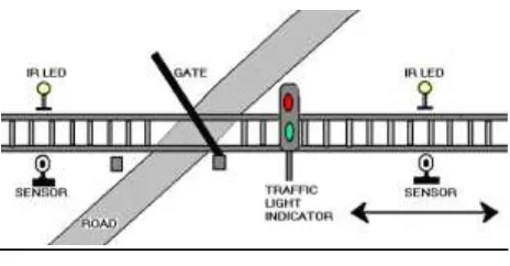
Signals are placed near the gate each at a specified distance. The train may be approaching the gate in either direction. So all signals are made RED to indicate the arrival of the train. the gate buzzer is made ‘ON’ , and road users need to be warned. The road user signals are made GREEN so that they can freely move through the gate buzzer is made ‘OFF’ since there is no approach of train and road users need not be warned.
In this model we are using a buzzer for the announcement and LCD for the purpose of display message. LCD is interfaced to microcontroller. The announcement and display message is according to the second sensor which should be used for the purpose of gate opening.
3.2.2 Train arrival detection:
Fig (3): IR sensors implementation
Fig (4): Approximate distance between two sensors
Available Online at www.ijpret.com 1568 R1, R2, R3 & R4 placed on either side of the gate. In particular direction of approach, R1 is used to sense the arrival; R3 is used to sense the departure of the train. In the same way R4&R2 senses arrival and departure in the other direction. Train arrival and departure sensing can be achieved by means of relay technique. A confined part of parallel track is supplied with positive voltage and ground. As wheels of the train, is made up of aluminum which is a conducting material, it shorts two parallel tracks. When the wheels of the train moves over it, both tracks are shorted to ground and this acts as a signal to microcontroller indicating train arrival. The train detection in the other direction is done in the same way by the sensors R1 & R4. These sensors are placed 5km before the gate.
3.2.3 Train departure detection:
Detection of train is also done using relay techniques as explained the head of train arrival detection. Sensor R3&R2 respectively considering direction of train approach do train departure. A message is displayed on LCD when train reaches the platform. Sensed by IR sensors.
3.2. POWER SUPPLY
Power supply unit consists of following units:
1. Step down transformer
2. Rectifier unit
3. Input filter
4. Regulator unit
5. Output filter
3.3.1 Step down transformer:
Available Online at www.ijpret.com 1569
3.3.2 Rectifier unit:
The Rectifier circuit is used to convert the AC voltage into its corresponding DC voltage. There are Half-Wave, Full-Wave and bridge Rectifiers available for this specific function. The most important and simple device used in Rectifier circuit is the diode. The simple function of the diode is to conduct when forward biased and not to conduct in reverse bias.
3.3.3 Input filter:
Capacitors are used as filter. The ripples from the AC voltage are removed and pure DC voltage is obtained. And also these capacitors are used to reduce the harmonics of the input voltage. The primary action performed by capacitor is charging and discharging. It charges in positive half cycle of the AC voltage and it will discharge in negative half cycle. So it allows only AC voltage and does not allow the DC voltage. This filter is fixed before the regulator. Thus the output is free from ripples.
3.3.4 Regulator unit:
Regulator regulates the output voltage to be always constant. The output voltage is maintained irrespective of the fluctuations in the input AC voltage. As and then the AC voltage changes, the DC voltage also changes. Thus to avoid this Regulators are used.
3.3.5 Output filter:
The principle of the capacitor is to charge and discharge. It charges during the positive half cycle of the AC voltage and discharges during the negative half cycle. So it allows only AC voltage and does not allow the DC voltage. This filter is fixed after the Regulator circuit to filter any of the possibly found ripples in the output received finally. Here we used 0.1μF capacitor. The output at this stage is 5V and is given to the Microcontroller.
3.4. IR SENSORS
This infrared sensor also called as IR sensors, consists of two parts:
1. IR transmitter circuit
2. IR receiver unit
Available Online at www.ijpret.com 1570
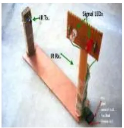
3.4.1 IR Transmitter unit:
IR LED:
The IR LED emitting infrared light is put on in the transmitting unit, To generate IR signal. IC 555 is used to construct an astable multivibrator which has two quasi- stable states. It generates a square wave of frequency 38kHz and amplitude 5Volts. It is required to switch ‘ON’ the IR LED.
3.4.2 IR Receiver unit:
The receiver unit consists of a sensor and its associated circuitry. In receiver section, the first part is a sensor, which detects IR pulses transmitted by IR-LED. Whenever a train crosses the sensor, the output of IR sensor momentarily transits through a low state. As a result the mono-stable is triggered and a short pulse is applied to the port pin of the microcontroller. On receiving a pulse from the sensor circuit, the controller activates the circuitry required for closing and opening of the gates.
3.5. EMBEDDED SYSTEM
3.5.1 Introduction:
A system is something that maintains its existence and functions as a whole through the interaction of its parts. E.g. Body, Access Control, etc. An embedded system is micro controller-based, software driven, reliable, real-time control system. Microcontrollers and Microprocessors are widely used in embedded system products. An embedded product uses a Micro controller to do one task only. A Printer is an example of embedded system that it is getting the data and printing it.
Embedded System is a combination of hardware and software used to achieve a single specific task.
Embedded systems are computer systems that monitor, respond to, or control an external
environment.
Environment connected to systems through sensors, actuators and other I/O interfaces.
Available Online at www.ijpret.com 1571
High-end embedded & lower end embedded systems:
High-end embedded system - Generally 32, 64 Bit Controllers used with OS. Example, Personal
Digital Assistant and Mobile phones etc.
Lower end embedded systems – Generally 8, 16 Bit Controllers used with a minimal operating
systems and hardware layout designed for the specific purpose. Examples Small controllers and devices in our everyday life like Washing Machine, Microwave Ovens, where they are embedded in.
3.5.2Embedded system tools:
Assembler:
An assembler is a computer program for translating assembly language —essentially, a mnemonic representation of machine language — into object code. A cross assembler produces code for one type of processor, but runs on another .Translating assembly instruction mnemonics into opcodes, assemblers provide the ability to use symbolic names for memory locations (saving tedious calculations and manually updating addresses when a program is slightly modified), and macro facilities for performing textual substitution — typically used to encode common short sequences of instructions to run inline instead of in a subroutine. Assemblers are far simpler to write than compilers for high-level languages.
Assembly language has several benefits:
Speed: Assembly language programs are generally the fastest programs around.
Space: Assembly language programs are often the smallest.
Capability: You can do things in assembly, which are difficult or impossible in High-level languages.
Simulator:
Available Online at www.ijpret.com 1572
Compiler:
A compiler is a program that reads a program in one language, the source Language and translates into an equivalent program in another language, the target language. The translation process should also report the presence of errors in the source program
3.6. MICROCONTROLLER
3.6.1 Introduction:
A computer-on-a-chip is a variation of a microprocessor, which combines the processor core (CPU), some memory, and I/O (input/output) lines, all on one chip. The computer-on-a-chip is called the microcomputer whose proper meaning is a computer using a (number of) microprocessor(s) as its CPUs, while the concept of the microcomputer is known to be a microcontroller. A microcontroller can be viewed as a set of digital logic circuits integrated on a single silicon chip. This chip is used for only specific applications.[1]
A designer will use a Microcontroller to:
1. Gather input from various sensors
2. Process this input into a set of actions
3. Use the output mechanisms on the Microcontroller to do something useful
4. RAM and ROM are inbuilt in the MC.
5. Cheap compared to MP.
6. Multi machine control is possible simultaneously.
Examples:
8051, 89C51 (ATMAL), PIC (Microchip), Motorola (Motorola), ARM Processor,
Applications:
Available Online at www.ijpret.com 1573
4. ALGORITHM
STEP 1: Start.
STEP 2: Set the variables.
STEP 3: Make initial settings of the signals for the train and road users.
STEP 4: Check for the arrival of the train in either direction by the sensors.
If the train is sensed go to STEP 5. Otherwise repeat STEP 4.
STEP 5: Make the warning signal for the road users and set the signal for the train.
STEP 6: Check for the presence of the obstacle using sensors. If there is no obstacle go to STEP 7. Otherwise repeat STEP 6.
STEP 7: Close the gate and stop the buzzer warning.
STEP 8: Change the signal for the train.
STEP 9: Check for the train departure by the sensors. If the train sensed go to next STEP. Otherwise repeat STEP 9.
STEP 10: Open the gate.
STEP 11: Go to STEP 3.
STEP 12: Stop.
5. FUTURE ENHANCEMENT
6.1: Track Switching:
Available Online at www.ijpret.com 1574
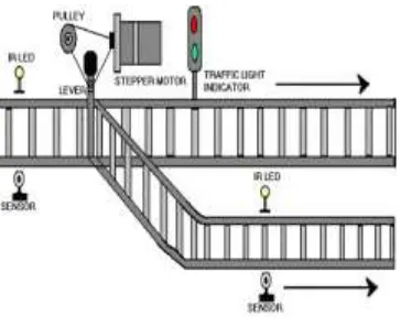
Fig (5): Track switching
Concept of automatic track switching. Considering a situation where in an express train and a local train are traveling in opposite directions on the same track; the express train is allowed to travel on the same track and the local train has to switch on to the other track. Indicator lights have been provided to avoid collisions .Here the switching operation is performed using a stepper motor. In practical purposes this can be achieved using electromagnets. For the ease of description we are considering only two plat forms thus this can be implemented to any number of platforms. When train reaches the platform before a 2km distance apart a set of sensors are placed to detect the train and two pair of sensors are placed on each of track at platforms. When the train is at the first pair of sensors it sends a signal to microcontroller to know the availability of plat form. Here after checking availability microcontroller operates stepper motor to change the track.
The mechanism is arranged as shown in fig. but in this case the track changing is done due to second sensor that used to open the gate.
6.2 Power supply:
Available Online at www.ijpret.com 1575
6.3 Sensing for vehicles:
Laser light is used as a source and LDR as a tool for sensing purpose. When light strokes on LDR its resistance decreases and when light does not strike LDR its resistance remains at normal value. This change of resistance of LDR is used for sensing by the micro controller by the use of compensation.
If there is no vehicle in between or beneath the gates, then the laser light from the source falls on the LDR since there is no obstacle. Since there is no vehicle or obstacle, signal is made GREEN for the train to pass through the gate. The same is applied for in the other direction and signals are made GREEN and gates are closed.
Due to some unavoidable circumstances, if there is a sudden breakdown of a Vehicle between the gate, then the light from laser source does not fall on LDR. It indicates the presence of vehicle and the signal for train should be made RED in order to slow down the train to avoid collision. Then the obstacle should be warned to clear the path.
We know that the rate of accidents increasing day by day, in this because failure of mechanism at track changing two trains coming on same track. This can also happens sometimes due to human negligence. This can avoided by using the following unmanned detection for two trains coming on same track case. In our model of project, we are using the gate controlling pair of sensors to execute this method. i.e., when two trains are coming same track at that location the two sensors will operate at a time i.e., two 555 timers of circuit are driven in to quasi stable state and thus corresponding two buzzer will operate at a time and two IR LED will operate and hence signal sends to micro processor to operate the stepper motor attack changing. The components that we use in order to execute are stepper motor 5v, µC AND IR sensors.
7. SCOPE OF PROJECT
This project is developed in order to help the INDIAN RAILWAYS in making its present working system a better one, by eliminating some of the loopholes existing in it.
Based on the responses and reports obtained as a result of the significant development in the working system of INDIAN RAILWAYS, this project can be further extended to meet the demands according to situation.
Available Online at www.ijpret.com 1576 This circuit can be expanded and used in a station with any number of platforms as per the
usage.
Additional modules can be added without affecting the remaining modules. This allows the
flexibility and easy maintenance of the developed system.
This system consists of following features over manual system:
There is no time lag to operate the device.
Accuracy.
Simulation is provided to reflect the present status of the system.
End user can operate this without knowing about electronics.
8. CONCLUSION
The idea of automating the process of railway gate operation in level crossings has been undertaken. As the system is completely automated, it avoids manual errors and thus provides ultimate safety to road users. By this mechanism, presence of a gatekeeper is not necessary and automatic operation of the gate through the motor action is achieved. Microcontroller performs the complete operation i.e., sensing ,gate closing and opening operation is done by software coding written for the controller. The mechanism works on a simple principle and there is not much of complexity needed in the circuit.
9. REFERENCES
1. “Principles of Electronics” by V.K.MEHTA.
2. International Journal of Modern Engineering Research (IJMER) Vol.2, Issue.1, Jan-Feb 2012 pp-458-463. www.ijmer.com
3. http://files.spogel.com/fypin-ece/p-00575--Automatic-Railway-Gate-Control.pdf
4. http://www.elprocus.com/automatic-railway-gate-control-system-projects-using
microcontroller
5. www.mitel.databook.com
6. www.atmel.databook.com
7. www.keil.com
8. www.8052.com/tutorial.phtml
Available Online at www.ijpret.com 1577 10.www.electronicsforu.com/electronicsforu/articles/hits.asp?id=1431
11.Programming Embedded Systems: With C and GNU Development Tools. By Michael Barr
12.Basic electronics By: GROB