Available Online at www.ijpret.com 93
INTERNATIONAL JOURNAL OF PURE AND
APPLIED RESEARCH IN ENGINEERING AND
TECHNOLOGY
A PATH FOR HORIZING YOUR INNOVATIVE WORK
PLANER IMPLEMENTATION OF SWITCHED-BEAM ANTENNA USING BUTLER
MATRIX FEED NETWORK
KSHIRSAGAR AN1, MALGE PS2
1. P.G. Student Electronics Department, Walchand Institute of Technology, Solapur, India 2. Assistant Professor Electronics Department, Walchand Institute of Technology, Solapur, India
Accepted Date: 24/10/2014; Published Date: 01/11/2014
\
Abstract: This paper concentrates on design & implementation of Buttler matrix feed Switched beam smart antenna system for 2.45 GHz ISM band. The butler matrix feeds the phase incremented signal to the antenna array to direct the beam in desired direction thereby reducing the problem of multipath fading, delay, interference. Basically there are two types of smart antenna systems; one is Switched beam system and another Adaptive array system. This paper presents optimum design and implementation of a switched beam smart antenna using 4x4 planar Butler matrix array. The beam forming network is formed using micro strip antenna and butler matrix (hybrid couplers, cross-coupler, phase shifter). All the individual components of butler matrix as well as the microstrip patch antenna is simulated and implemented. Finally the prototype is simulated using HFSS software and implemented on low cost FR4 substrate. The coupling effect among different ports are investigated.
Keywords: Switched Beam antenna, Butler matrix, microstrip antenna.
Corresponding Author: MR. AMIT N. KSHIRSAGAR
Access Online On:
www.ijpret.com
How to Cite This Article:
Kshirsagar AN,Malge PS,IJPRET, 2014; Volume 3 (3): 93-103
Available Online at www.ijpret.com 94
INTRODUCTION
In the recent years topic of multi-beam smart antenna has been receiving much attention. A smart antenna system combines multiple antenna elements with a signal processing capability to optimize its radiation transmission and reception pattern adaptively in response to the available signal environment. Smart antenna system have been introduced to improve wireless performance and to increase the capacity[7] by spatial filtering, which can separate spectrally and temporally overlapping signals from multiple users.
Multiple beam smart antennas have wide range of applications. Different multi-beam antenna prototypes are implemented for the applications in base stations [4], to improve the quality of transmission and enhance the cellular capacity, range, and coverage [6] because the antenna array is capable of pointing to desired targets automatically in real time. Moreover, the multipath fading and interferences phenomenon in communications systems can be solved using switched beam antenna array for rejecting interference signals
Available Online at www.ijpret.com 95
DESIGN AND ANALYSIS
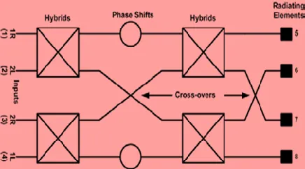
The structure of beamforming network [1] with array elements is as shown in figure 1. This matrix generates a set of N orthogonal beams from the N antenna elements of an equispaced linear array. For simulation, though the data was considered for a range of 1.5 to 3 GHz frequency, but the individual component designs were done at 2.4 GHz. The final design is fabricated on FR4 board, with substrate height of 1.6mm, r = 4.4, tan = 0.0027.
In this we simulate the Butler Matrix. The N × N Butler matrix creates a set of N orthogonal beams in space by processing the signal from the N antenna elements of an equispaced linear array. These beams are pointing in direction θ governed by the following equation [8]:
………... (1)
Where i = 1, 2, 3… (N-1). The corresponding inter element phase shift with spacing d=λ/2 is
)……….. (2)
Where β = 2π/λ, is the wave number. The optimum design of 4x4 planar Butler matrix array which consist of phase shifters. Butler matrix has four in-puts 1R, 2L, 2R, 1L and four outputs. These four outputs are used as inputs to antenna elements to produce four beams. The input ports of the Butler matrix are named according to their beam position.
Fig. 1 Structure of Butler matrix fed array
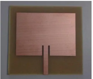
A. Microstrip antenna
Available Online at www.ijpret.com 96 radiated field obtained at normal to the structure surface. Hence to take care of this new problem of the fringing fields along the width, the patch length is extended on both sides by additional length given by[8],
……….... (3)
Where,
However the element spacing was kept constant throughout the four patch antennas [2].
B. Butler Matrix
The Butler matrix is a beam forming network. It is formed using four 900 hybrid, two zero dB crossover and 450 phase shifter. The butler matrix perform constant phase gradient. The output of butler matrix is used to radiate the array elements forming the beams in different direction.
The 900 hybrid is simulated and S parameters are analyzed. The result ensures the required phase shift. Zero dB Crossover coupler is designed by cascading two 900 hybrids. The result for crossover is given in fig 6. The phase shifter is implemented using microstrip transmission line. The length of the line corresponding to 450 phase shift is given by the formula
………... (4)
Where L is in meters, φ is in radians. λ is the wavelength in the microstrip line. The wavelength in the microstrip transmission line is given by
……….. (5)
Where λ0 is the free space wavelength and ϵreff is the effective dielectric constant of the
Available Online at www.ijpret.com 97
EXPERIMENTAL SETUP AND RESULTS
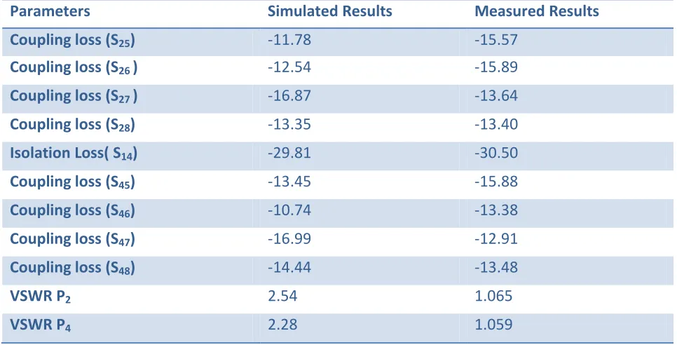
The design simulation process has been successfully done using Ansoft HFSS 13.0. For simulation, the data was considered for a range of 1.5 to 3 GHz frequency. The final design is implanted on FR4 board. The CorelDraw Graphic Suite 12 has been used to transform the circuit from HFSS 13.0 into layout printable on transparency. The designed prototypes have been measured using Network Analyzer. The measurement results have been compared to the simulation results. The results for butler matrix are given in table 1. The isolations from the input ports are greater than 20 dB. The coupling losses are also nearly 10 dB giving constant magnitude at the output ports. This ensures the correctness of the implemented design. However, there are still some mismatches occur inside the matrix and cause the small differences in the magnitude at the output ports.
The results for final prototype are summarized in table 2. The return loss, isolation loss and VSWR signify the good results. The far field radiation characteristics of the beams for final prototype are obtained by exciting different ports in HFSS simulation software. Fig. 16 illustrates radiation patterns of 1L, 2R, 2L, and 1R beams respectively. From the radiation patterns, it is shown that the angles of the four beams associated with different inputs are -380, 520, -540, and 400. For all the beams side lobe levels (SSL) are lower than –10 dB. However, the SSL of the 1L and 1R beams, corresponding to the beams is due to the mutual coupling effects between the radiating elements as well as the slightly mismatches between the feeding network and the antennas.
Available Online at www.ijpret.com 98
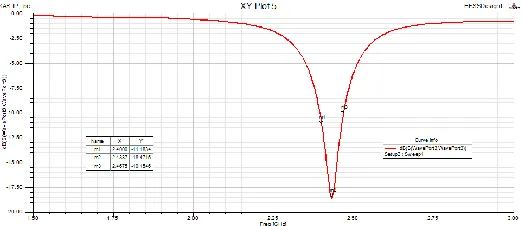
Fig. 3 Return loss for Microstrip patch antenna.
Fig. 4 VSWR for microstrip patch antenna.
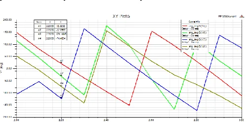
Fig. 5 S-Parameters for 90 degree hybrid.
Available Online at www.ijpret.com 99
Fig. 7 Return loss for phase shifter
Fig. 8 Transmission coefficient for port 2 of Buttler Matrix.
Fig. 9 Isolation parameters for port 2 of Buttler matrix
Available Online at www.ijpret.com 100
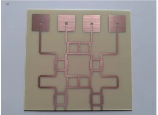
Fig. 11 Implemented Butler Matrix feed network.
Table 1: Summary of Practical Results for Butler Matrix
Parameters Simulated Results Measured Results
Coupling loss (S25) -11.78 -15.57
Coupling loss (S26 ) -12.54 -15.89
Coupling loss (S27 ) -16.87 -13.64
Coupling loss (S28) -13.35 -13.40
Isolation Loss( S14) -29.81 -30.50
Coupling loss (S45) -13.45 -15.88
Coupling loss (S46) -10.74 -13.38
Coupling loss (S47) -16.99 -12.91
Coupling loss (S48) -14.44 -13.48
VSWR P2 2.54 1.065
Available Online at www.ijpret.com 101
Table 2: Summary of Practical Results for Switched Bream system prototype
Parameters Simulated Results Measured Results
Return Loss( S22) -16.05 -34.13
Return Loss( S44) -11.74 -28.17
Isolation ( S12) --- -28.66
Isolation ( S23) --- -41.20
Isolation ( S14) --- -27.89
VSWR P2 1.35 1.099
VSWR P4 1.48 1.077
Available Online at www.ijpret.com 102
Fig. 13 Measured beam patterns at 2.45 GHz when a. port 1R is fed, b. port 2L is fed, c. port 2R is fed, and d. port 1L is fed.
CONCLUSION
Available Online at www.ijpret.com 103
REFERENCES
1. Microstrip Antenna Array with Beam forming Network for WLAN Applications Nhi T. Pham1, Gye-An Lee2, and Franco De Flaviis Department of Electrical Engineering and Computer Science.
2. M. El-Tager and M. A. Eleiwa Electronics Department, M. T. C., Cairo, Egypt Design and Implementation of a Smart Antenna Using Butler Matrix for ISM-band Progress In Electromagnetic Research Symposium, Beijing, China, March 23{27, 2009}
3. Progress In Electromagnetic Research, PIER 74, 131–140, 2007 WIDEBAND X-BAND MICROSTRIP BUTLER MATRIX J. He, B.-Z. Wang, Q.-Q. He, Y.-X. Xing, and Z.-L. Yin.
4. Application of Butler Matrix to a Tree Structure of Microstrip Antenna Array by Tomader Mazri1, Fatima Riouch2 and Najiba El Amrani El Idrissi3 International Journal of Computer Science Issues, Vol. 8, Issue 4, No 2, July 2011.
5. “Design and Implementation of a 4x4 Butler-Matrix Switched-Beam Antenna Array” by G.A. ADAMIDIS and I.O. VARDIAMBASIS
6. “Implementation of Beam Formation for WMNs” by M. Uthansakul, S. Pradittara, P. Uthansakul. WSEAS TRANSACTIONS on COMMUNICATIONS Issue 12, Volume 9, December 2010.
7. “Study of a Planar Topology ButlerMatrix for Printed Multibeam Antenna” by Guenad Boumediene1, Meriah Sidi Mouhamed2 and Fethi Tarik Bendimerad3 International Journal of Computer Science Issues, Vol. 9, Issue 6, No 3, November 2012.
8. Wriddhi Bhowmik and Shweta Srivastava, "Optimum Design of a 4x4 Planar Butler Matrix Array for WLAN Application", Journal Telecommunication Volume 2 Page-68-74,Volume-April-2010.
9. “A New Design of Compact 4 × 4 ButlerMatrix for ISM Applications” by Mbarek Traii, Mourad Nedil, Ali Gharsallah, and Tayeb A. Denidni International Journal of Microwave Science and Technology Volume 2008.