Comparison of Control Algorithms Using a Generalized Model for a
Human with an Exoskeleton
Antonio Concha
a, Francisco Emmanuel González Sánchez
b, Efrain Ramírez Velasco
c,
Martín Sánchez
b, Suresh Kumar Gadi
b,*a
Facultad de Ingeniería Mecánica y Eléctrica, Universidad de Colima, Colima
bFacultad de Ingeniería Mecánica y Eléctrica, Universidad Autónoma de Coahuila, Torreón
cDepartamento de Eléctrica-Electrónica, Instituto Tecnológico de Aguascalientes
Abstract
This article proposes a pictorial representation of a generalized model for a human with an exoskeleton. This model is useful for comparing control techniques and allows identifying the sensor and actuator requirements for a particular control algorithm. Moreover, the pictorial model displays the control algorithms in block diagrams showing the details of these algorithms. In order to show the utility of this model, the following four control schemes are compared: 1) Kazerooni's algorithm, 2) BLEEX’s algorithm, 3) technique inspired by fictitious gain, and 4) Force control with velocity and position feedback. The hardware and software requirements for these control algorithms are also discussed.
Keywords: Force augmenting device, exoskeletons, Human-Robot Interaction, closed-loop control.
1. Introduction
There is a growing interest in the area of human-robot interactions[1]–[3], which are of two types: 1) Teleoperation, where mechanical forces between humans and robot arms are not exchanged; and 2) Human-exoskeleton interaction, where the robot and the human arms produce reaction forces on each other. This article is focused on the second kind of interaction, where the human and exoskeleton are in contact all the time. The exoskeletons, also called in this document as force augmenting devices (FADs), can be used in various applications ranging from active prosthetics, material handling, military, space research, etc. [4]–[8]. Since the FADs are always in contact with the human, the stability analysis of their control algorithms is of extreme importance.
2. General representation of a Human-Robot interaction
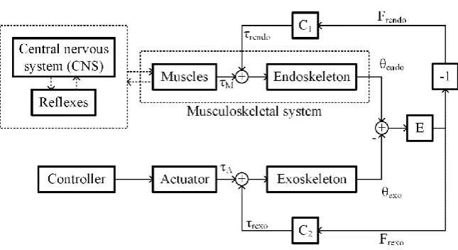
Figure 1. Block diagram showing a general scheme of Human-Robot interaction.
Figure 1 shows a block diagram depicting a human arm (HA) - force augmenting device (FAD) interaction, where two controllers work in parallel, one consists in the Central nervous system of a human and another operates the actuator of the FAD. The human operator generates the desired trajectory and exerts torques that permits the FAD to follow the desired trajectories closely. The electronics in the exoskeleton measures the human interaction with sensors and provides low mechanical impedance in the human’s desired trajectory with the help of actuators [9].
The blocks: Central nervous system (CNS), Reflexes, Muscles and Endoskeleton represent the dynamics associated with the human arm movement. The CNS performs the Coordinate transformation, the Trajectory planning, and the Motor command generation [10]–[12]. Hence the CNS generates the desired trajectory and passes the information to the spinal cord. A closed-loop feedback control is executed by the reflexes in the spinal cord in order to move the arms, whose trajectory mimics the desired human arm trajectory as closely as possible [13], [14].
The difference between the human arm position
endoand the exoskeleton arm position
exo causes a force, which is written asFrexo FrendoE(
endo
exo), whereF
rexo andF
rendoare the reaction force generated on the exoskeleton and the human arm respectively. The termE
(.)
is a nonlinear function, which maps the difference between
endo and
exo toF
rexoandF
rendo. The reaction torque experienced by the human arm
rendo and exoskeleton arm
rexo is given by
rendo C F1 rendo and
rexo
C F
2 rexo, respectively, whereC
1 andC
2 are positive constants. Moreover,
M is the torque exerted by the muscles,
A is the torque produced by the exoskeleton’s actuators. Usually the objective of the control algorithms is to generate
A proportional to
M. The constantK
Ais an amplification factor. In other words, the FAD amplifies the muscle power by a factor ofK
A. If a value ofK
A
1
is selected, the FAD attenuates the torque exerted by the human muscle through the production of an opposite torque. It is worth mentioning that FADs withK
A
1
are used in rehabilitation robots [15].3. Control schemes
3.1 Kazerooni's algorithm
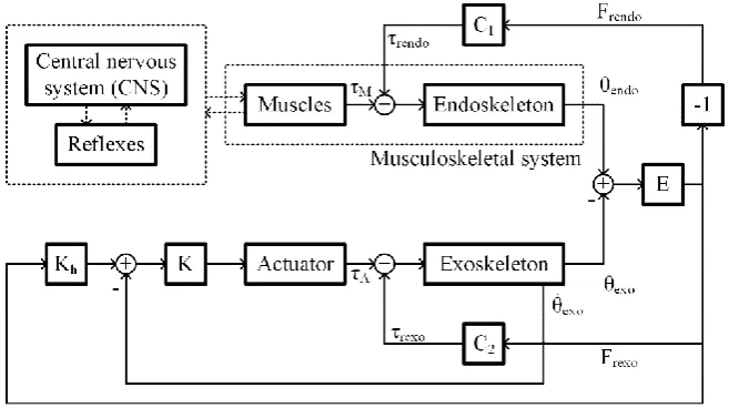
Figure 2: Block diagram showing Kazerooni’s algorithm applied to Human-FAD interaction.
Figure 2 depicts the control scheme presented by Kazerooni in [16], where the author uses linear dynamic models to represent the dynamics of the CNS, endoskeleton, and function
E
(.)
. Author assumes thatK
h and K are linear dynamic systems. Through this control scheme, the velocity of the exoskeleton arm is controlled. The difference between the human arm position and the exoskeleton one causes a velocity in the exoskeleton arm that allows cancelling this difference in position. Signalrexo
F
is measured by means a force sensor, and the exoskeleton arm position remains stationary in thecase that the user is having no interaction with the force sensor.
In Figure 2 it can be observed that the controller requires two inputs, one is the velocity of the exoskeleton arm and the other input comes from the HA-FAD interaction force. Hence a force sensor and an encoder or a tachogenerator is required.
Figure 3 shows the BLEEX control scheme proposed in [17], [18], which does not use any force sensor. A positive feedback loop is used to increase the sensitivity of the FAD to external disturbances. The controller
C s
( )
is given byC s
( )
(1
) ( )
G s
, whereG s
( )
is the exoskeleton dynamics and
is an augmentation factor. Signal
rexo introduces external disturbances into the positive feedback system. Due to the high sensitivity of the FAD controller towards external disturbances, the exoskeleton arm follows the human arm. It is important to mention that the design of the controller needs the knowledge of an accurate model of the actuator and the inverse model of the exoskeleton arm.From Figure 3 it can be observed that the controller uses only one feedback loop. This controller estimates the torque exerted by the HA-FAD interaction by computing the perturbations in the exoskeleton velocity. This helps us to identify that the actuator should be bidirectional, i.e. its position should be sensitive to both the torque from the actuator and the force from the HA-FAD interaction. Actuators based on ball-screw mechanisms are not bidirectional, hence they should be avoided.
3.3 Algorithm inspired by fictitious gain
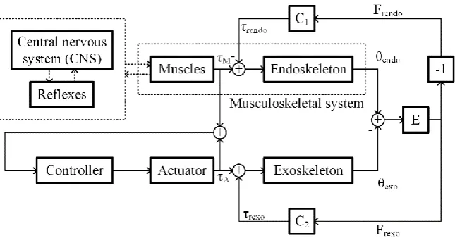
Figure 4. Block diagram showing the algorithm inspired by fictitious gain applied to Human-FAD interaction.
Figure 4 shows a control scheme, inspired by a fictitious gain, presented in [19]. This control scheme needs a positive feedback, which consist in the sum of the torques exerted by the muscles and the actuator. As the algorithm mentioned in the previous subsection, the actuator inverse dynamics is employed by the controller. The torque exerted by the muscles can be estimated by an Electromyography (EMG) sensor, a muscle hardness sensor, or a muscle fiber expansion sensor. Since this control scheme uses a positive feedback, the closed-loop sensitivity of the torque exerted by the muscles, is high. The author of this algorithm also proposes a methodology for adapting this algorithm to users that suffer tremors.
3.4 Force control with velocity and position feedback
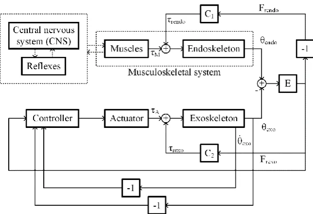
Figure 4. Block diagram showing the force control algorithm with position and velocity feedback applied to Human-FAD interaction.
In this control scheme, presented in [9], authors use a linear model for the CNS, spinal cord, muscles and endoskeleton human arm; and
E
(.)
is approximated as a constant. The actuator dynamics is ignored by introducing its inverse dynamics into the controller, which provides an amplifying effect of
rexo. The actuator does not provide any torque while the human arm is released, which will bring the exoskeleton to the equilibrium point. Additionally, the controller provides a velocity and position feedback for obtaining the desired performance under no human contact. This control scheme is similar to the Kazerooni’s control scheme with a position feedback. It is worth mentioning that the authors of [20] present a methodology to calculate the upper-limit of the augmentation factor. It is observed that the human-FAD interaction would be stable for any value of the augmentation factor if the internal delay of the human reflex action is zero.From Figure 5, it can be observed that controller requires three sensors, which are position, velocity and force sensors.
3.4 Comparison between the controllers
Table 1. Comparison between the four control algorithms under study Kazerooni's algorithm BLEEX’s algorithm Algorithm inspired by fictitious gain Force control with velocity and position feedback
Sensors used Force sensor Encoder or
tachogenerator Electromyography (EMG) sensor Force sensor Disadvantages with sensors Since the exoskeleton may make contact at various points, placing a force sensor is tricky.
None 1. Placing EMG
sensor is difficult. 2. Processing EMG signal is difficult compared to processing a force sensor signal. 3. Calibrating EMG sensor is time-consuming
Since the exoskeleton may make contact at various points, placing a force sensor is tricky.
Control algorithm complexity Easy to implement Difficult:
1. The model should be accurate.
2. Parameters should be estimated
accurately.
3. Controller should implement the inverse dynamics Difficult to implement: 1. Parameters should be estimated accurately. 2. Controller should implement the inverse dynamics Easy to implement Limitations of the control scheme
Users do not experience part of the load that they are handling when the
exoskeleton arm is stationary
1. Stability is not guaranteed.
2. The algorithm may not differentiate between
perturbations caused by human and external sources.
There is a limitation on the mass of the exoskeleton structure. Requires position, velocity, and interaction force feedback.
4. Conclusions
References
[1] Nagarajan, U., Aguirre-Ollinger, G., and Goswami, A. (2016). Integral admittance shaping: A unified framework for active exoskeleton control, Rob. Auton. Syst., Vol. 75, 310–324.
[2] Gopura, R. A. R. C., Bandara, D. S. V., Kiguchi, K. and Mann, G. K. I. (2016) “Developments in hardware systems of active upper-limb exoskeleton robots: A review,” Rob. Auton. Syst., Vol. 75, 203–220.
[3] Manns, P. Sreenivasa, M. Millard, M. and Mombaur,K. (2017). Motion Optimization and Parameter Identification for a Human and Lower Back Exoskeleton Model, IEEE Robot. Autom. Lett., Vol. 2, No. 3, 1564–1570.
[4] Dellon, B. and Matsuoka, Y. (2007). Prosthetics, Exoskeletons, and Rehabilitation [Grand Challenges of Robotics],” IEEE Robot. Autom. Mag., vol. 14, no. 1, pp. 30–34, Mar. 2007.
[5] Makinson, J. B., Bodine, D. P., & Fick, B. R. (1969). Machine augmentation of human strength and
endurance Hardiman I prototype project (No. S-69-1116). General Electric Co Schenectady NY Specialty
Materials Handling Products Operation.
[6] Jansen, J., Richardson, B, Pin, F., Lind, R., and Birdwell, J. (2000). Exoskeleton for Soldier Enhancement Systems Feasibility Study, Oak Ridge, Tennessee 37831.
[7] Schiele, A. and Visentin, G. (2008). Exoskeleton for the Human Arm, in Particular for Space Applications,
United States Pat. 7410338B.
[8] Guizzo E., and Goldstein, H. (2005). The Rise of the Body Bots [robotic exoskeletons],” IEEE Spectr., vol. 42, no. 10, pp. 50–56, 2005.
[9] Lee, S. and Sankai,Y. (2002). Power Assist Control For Leg With Hal-3 Based on Virtual Torque and Impedance Adjustment, Systems, Man and Cybernetics, IEEE International Conference on, Vol. 4.
[10] Schweighofer, N. Arbib, M. A. and Kawato, M. (1998). Role of the Cerebellum in Reaching Movements in Humans. I. Distributed Inverse Dynamics Control, Eur. J. Neurosci., Vol. 10, No. 1, 86–94.
[11] Shaikh, A. G., Meng,H. and Angelaki, D. E. (2004). Multiple Reference Frames for Motion in the Primate Cerebellum,” J. Neurosci., Vol. 24, No. 19, 4491–4497.
[12] Bastian, A.J., Martin, T.A., Keating, J.G. and Thach, W.T. (1996). Cerebellar Ataxia: Abnormal Control of Interaction Torques Across Multiple Joints, J. Neurophysiol., Vol. 76, No. 1, 492–509.
[13] McIntyre, J. and Bizzi, E. (1993). Servo Hypotheses for the Biological Control of Movement, J. Mot.
Behav., Vol. 25, No. 3, 193–202.
[14] Randall F.J and Ostry,D. (1990). Trajectories of Human Multi-Joint Arm Movements: Evidence of Joint Level Planning, Experimental Robotics I, 594–613.
[15] He, W., Ge, S. S., Li, Y., Chew, E., and Ng, Y. S. (2015). Neural Network Control of a Rehabilitation Robot by State and Output Feedback. Journal of Intelligent & Robotic Systems, Vol. 80, No.1, 15-31. [16] Kazerooni, H. (1988). Human Machine Interaction via the Transfer of Power and Information Signals,
ASME Winter Annu. Meet.
[17] Kazerooni, H., Racine, J.L., Huang, L. and Steger, R. (2005). On the control of the berkeley lower extremity exoskeleton (BLEEX), Proceedings of the 2005 IEEE International Conference on Robotics and
Automation, 2005. ICRA 2005., 4353–4360.
[18] Kazerooni, H. and Steger, R. (2006). The Berkeley Lower Extremity Exoskeleton, J. Dyn. Syst. Meas.
Control, Vol. 128, No. 1, 14–25.
[19] Kong, K. and Tomizuka, M.(2009). Control of Exoskeletons Inspired by Fictitious Gain in Human Model,
IEEE/ASME Trans. Mechatronics, Vol. 14, No. 6, 689–698.