Please cite this article as: S. Mahmood Ali, Optimization of Centrifugal Casting Parameters of AlSi Alloy by using the Response Surface Methodology (RSM), International Journal of Engineering (IJE), IJE TRANSACTIONS B: Applications Vol. 32, No. 11, (November 2019) 1516-1526
International Journal of Engineering
J o u r n a l H o m e p a g e : w w w . i j e . i rOptimization of Centrifugal Casting Parameters of AlSi Alloy by using the Response
Surface Methodology
S. Mahmood Ali*
Biomedical Engineering Department, University of Technology, Iraq
P A P E R I N F O
Paper history:
Received 23 July 2019
Received in revised form 6 September 2019 Accepted 12 September 2019
Keywords:
Horizontal and Vertical Centrifugal Casting Response Surface Methodology
Hypoeutectic AlSi Alloy Design of Experiments G- factor and Mold Rotation Speed
A B S T R A C T
Centrifugal casting is one of the advanced casting branches widely used in the metallurgical industry in which the centrifugal force helps strengthen the workpiece material.The present work attempt to study the effect of the horizontal and vertical centrifugal casting parameters included the centrifugal mold rotation speeds and G-factors values on the quality of the product. The work has been completed with design and fabricated of a low cost horizontal and vertical centrifugal casting machine with the main accessories for producing a hypoeutectic aluminum silicone (AlSi) alloy (content 10 % Si) specimens. The experimental results were analyzed and improved by using the statistical computer program “Design Expert 11” and response surface methodology (RSM). The results showed that for vertical and horizontal casting processes, the finest surfaces quality was achieved when working at mold rotation speed from 520 to 690 and 950 to 1230 RPM, i.e., with an average value of the G-factor = 69 and 50, respectively. The proof stress values were increased with increasing the mold rotation speed up to (690 RPM) and (1230 RPM) or used the G- factor value of 87.99 and 60.96 gave an increase in proof stress by 6.7 and (20.62% for vertical and horizontal casting experiments compared with gravitational casting, respectively. The obtained tensile strengths values were improved by 38.6 and 45.41 %, compared with the gravitational casting, respectively; while the percentage elongations were reduced to 0.281and 0.291 %; which means decreased by 33.45 and 31.69 % for the vertical and horizontal centrifugal casting compared with the values obtained by gravitational casting experiments, respectively.
doi: 10.5829/ije.2019.32.11b.02
1. INTRODUCTION1
Today casting is the sixth largest manufacturing industry in the world. Centrifugal casting is an advanced casting process, in which the desired shape of the required component was produced by benefiting the centrifugal force generated by rotating mold to force the molten metal against the mold wall till the metal has solidified. About 15% of the total casting products of the world are producing by centrifugal casting. Centrifugal casting is used when a hard-tough exterior surface must be combined with a high wear resistant surface. It is the quickest and economical method for producing a superior quality and high-density casting.
*Corresponding Author Email: [email protected] (S. Mahmood Ali)
All metals, alloys, nonmetals and virtually any material that can be liquidized and pourable can be cast by centrifugal casting processes for producing an isotropic and a dense product, including carbon and alloy steels, gray and ductile iron, stainless steels, copper, aluminum and magnesium alloys, nickel, cobalt and titanium based alloys and also nonmetals, including plastics, ceramics, glasses [1], by using a stainless steel, cast iron and graphite mold materials [2]. The process has become widely used for producing special castings tubes, pipes, rolls, cylinder liners and other axisymmetric parts [3-5]. The final quality of the products is depending upon the rate of solidification, the rotational speeds of the mold and the molten metal flow pattern [5].
rotating axis: horizontal, vertical, or slightly inclined. The horizontal centrifugal casting involves rotating the mold in a horizontal axis. It is used mainly for making pipes, tubes, bushings, cylinder sleeves (liners), gun barrels, sleeves, rods, rings, etc. [6-10]. Vertical centrifugal casting machine is essentially a pressure casting technique, where the mold is rotated in a vertical axis. It must be constructed to withstand static and dynamic loads imposed on it, where the dynamic loading is the most critical, thus the machine must be fastened and centered. It produces a non-cylindrical (or even nonsymmetrical) parts with high dimensional accuracy and high strength and then enhances the quality [8, 9]. This method is used for casting of parts with too thin sections or for large diameters or short lengths like gears, piston ring, impellers, propellers, bushings, railway wheels, the turbine vanes and blade in an aircraft jet engine, cams and levers in automotive control panels and jewelry.
The centrifugal effects can be divided as centrifugal pressure; intrinsic vibration of the process; and fluid dynamics [11]. Many investigations have been directed to study the effect of the process parameters including, the mold rotational speed, fluids and filling behaviors with different temperatures and speeds on the rate of solidification of the centrifugal casting products [3, 6, 12-14]. To study and optimize the influence of process centrifugal casting parameters on the mechanical properties during fabricating of aluminum alloy (5500), Shailesh et al. have been used the design of experiments technique (DOE) and the Taguchi method, to improving these properties such as, the elongation, the ultimate tensile strength (UTS) and Brinell hardness number (BHN). The optical microscope and the scanning electron microscope (SEM) were used to study the microstructures [15].
The high specific strength aluminum-silicon (AlSi) alloys offering a low thermal expansion coefficients influenced by their physical properties, the chemical composition, microstructure and their mechanical properties, including the high fatigue strength (allows pistons to work with thinner wall sections and lower weight), a lower friction, and the high hardness of silicon particles offering better wear resistance. These AlSi alloys are low-cost and very economically produced, used for automotive components such as pistons, connecting rods, cylinder heads, cylinder liners, turbochargers, impellers, actuators, brake calipers, and rotors. The piston is the most critical component of an internal combustion engine. It must withstand extremely hard conditions, high pressures and temperatures and heavy stresses [12-14]. AI-Si alloys fall into three major categories: Hypoeutectic (<12% Si), eutectic (12-13% Si) and hypereutectic (14-25% Si), where higher silicon contains exhibits excellent dimensional stability, surface hardness and wear resistant properties [16].
The present study aims to achieve some objectives, including studying the effect of the main process parameters for the designed and fabricated a multi-speeds horizontal and vertical centrifugal casting machines on the quality and solidification process of the fabricated hypoeutectic aluminum silicone (AlSi) alloy specimens using different centrifugal rotational speeds to reach the best mechanical properties and quality of the products. The present investigation was focused also on analyzed and improved the processes performances results of the conducting experiments by using the quadratic model power transform, the full factorial design (FFD) response surface methodology (RSM) and the new version of the powerful statistical computer program “Design Expert 11”. To optimized the processes performances, the design of experiments (DOE) technique method was used.
2. DESIGN OF THE VERTICAL AND HORIZONTAL CENTRIFUGAL CASTING MACHINES
To ensure the efficiency of the performance, all major components of the fabricated horizontal and vertical centrifugal casting machines were designed to withstand the applied static and dynamic loadings to resist the effect of imbalance forces associated in the mold during spinning action. The design analysis included, the centrifugal forces, the powers, and torques generated by the spinning parts and other design calculations considered in the following items [1, 4, 17].
For each machine, a two-speed motor (1420 and 950 RPM), has been selected. For the vertical machine, two motor pulleys with sheave diameters of 65 and 85 mm and three driven pulleys with sheave diameters of 75, 155 and 175 mm were fabricated, while for the horizontal machine, five pulleys with a sheave diameters of 65,75X2, 155, and 175 mm were fabricated to obtain five mold centrifugal rotational speeds for each centrifugal casting machine determined by following equation:
1 1 2
2
N d
N d
= (1)
where; N1 is the motor rotation speed (RPM); N2 is the
mold rotational speeds (RPM); d1 is the sheave diameter
of motor pulley = 75 mm and d2 is the sheave diameter
of driven pulley (mm). The calculated mold rotation speeds for the designed vertical machine are; 0, 350, 520, 820 and 960 RPM, and for the horizontal machine are; 0, 405, 690, 950, 1230 and 1420 RPM, where the first speed was used for the first casting experimental subgroup done by gravitational force only.
machines, respectively. Then, the length of the belt of the machine can be calculated as follows [17]:
2 2 1
1 2
( )
2
2( ) 4
d d
L C
d d C
−
= + +
+ (2)
where; L is the effective outside length of the belt (mm); C is the center distance between the two pulleys (mm). Then the used belt lengths are = 750, 950, 1000, 1075 and 1125 mm. To calculate the angular velocities of the rotating mold, the following equation can be used:
60 m m
D N
V = (3)
where; is the angular velocity of the mold (m/s) and Dm is the circle diameter of the rotating mold (mm).
Then the designed angular velocities for the vertical machine are 0, 7.21, 10.64, 14.09 and 16.81 and for the horizontal machine are 0, 1.53, 2.59, 3.58, 4.64 and 5.35 m/s.
The angular velocity of the driven pulley can be calculated by following equation:
2
2 60
N
= (4)
By using the driven pulleys speeds as 0, 350, 520, 820 and 960 and 0, 405, 690, 950, 1230 and 1420 RPM, then the obtained angular velocities were 0, 36.75, 54.60, 86.1, 100.8 and 0, 42.62, 71.94, 99.48, 128.81, 148.70 rad/s for vertical and horizontal machines, respectively.
Then the calculating of the centrifugal accelerations were done by using the angular velocities as mentioned in above and radius of the mold circle = 36mm for horizontal mold, then:
2
.
a= r (5)
The obtained designed centrifugal accelerations were 0, 0.020, 0.057, 0.063, 0.182 and 0.243 m/s2.
For calculating the mass and volume of melted metal for each vertical experiment, where the workpiece dimensions are 10mm diameter and 65 mm length, while the workpiece pipe dimensions for the horizontal machine are 75mm outer diameter, 3 mm thickness and 172 mm length, then the poured metal volume is:
2
. .
V =r I (6)
Where; V is the volume of poured metal, then V = π. (0.52 X
6.5) =5.105 cm3for the vertical mold and V = π X (3.752 –
3.452) X 17.2 =116.72 cm3 for the horizontal mold then the mass of poured metal can be calculated as follows:
( )
( )
M= Volume V X Density of AlSi alloy Xk (7)
where; M is the mass of the melted metal (g); and k is the increased mass ratio of melted metal to product mass. Then M = 5.105 X 2.7X 1.2 = 16.54 g for the vertical molding and M= 116.72 X 2.7= 315.13 g
for the horizontal molding.
Now, to calculate the centrifugal forces applied on the inner wall of the rotation mold and by using the maximum calculated angular velocity of the mold (Vm)
and the design mass of the melted metal (M) as 16.5 g and the rotational circle radius of the mold = 195mm for vertical mold and = 315 g and the radius of the mold = 36 mm for horizontal mold, then the centrifugal forces applied on the inner wall surface of the centrifugal casting machine is [5]:
2
( )
M V m F
r
= (8)
where; F is the centrifugal force on the machine mold, (N); r is the circle radius of the mold (m), then the obtained centrifugal forces values corresponding to each experimental rotational speed were 0. 4.27. 9.29, 16.29, 23.19 and 0, 20.48, 58.70, 112.14, 188.38 250.45 N for vertical and horizontal machines, respectively. Then the generated mold torques can be calculated by:
T = F r (9)
where; T is the torque generated (N.m), and the calculated torques values were 0, 0.83, 1.81, 3,18 and 4.52 and 0, 0.74, 2.11, 4.04, 6.78, 9.02 N.m for vertical and horizontal machines, respectively.
The pushing force (FP) on the mold endplates
generated by the horizontal spinning metal was expressed by the following equation:
2 2 2
5.375. ( ) ( )
(100)
p
N
F = do −di (10)
where, ρ is the molten metal density (= 2700 Kg/m3); N is the mold spinning speed (= 1420, 1230, 950, 690 and 405 RPM); dO is the outside diameter of the casting
product (0.075m) and di is the inside diameter of the
casting product (0.069m), then the obtained pushing forces corresponding to each mold rotational speed was 0, 207.70, 591.79, 1131.63, 2528.32 and 2528.32 N.
The required power for the designed machine for each centrifugal torque and angular speed can be determined by the following relation:
2
2 60
N T
P= (11)
where; P is the required power (W) and they were calculated equal to 0, 0.047, 0.099, 0.23, 0.39 and 0, 0.384, 0.649, 0.897, 0.837, 1.341 KW for vertical and horizontal machines, respectively.
3 16 ( ) (2 )2)
d Kb Mb Kt T
= (12)
where; Mb is the bending moment (N.m) =F x L; L is the distance from the point of action of centrifugal force (F ) to the supporting bracket (= 0.08 and 0.06 m); is the allowable shear stress for the high strength steel material (= 40 MN/m2); d is the shaft diameter (mm); Kb is the shock and fatigue factor applied to bending moment and Kt is the shock and fatigue factor applied to torsional moment. From literature [1], the values of the above factor are; Kt = 1.5 and Kb = 2.0, then the
designed machine shaft diameter (d=21.43 X 1.15 (using a safety factor = 24.64mm), i.e. the minimum fabricated shaft diameter was 25 and 20 mm for vertical and horizontal machines, respectively.
The machine shaft bearings lives were calculated by using the following equation [1]:
6
10 10
60 L L
N
=
(13)
where; L is the bearing life (in million revolutions); L10
is the factor chosen for the rating life of the bearings (for 90% reliability, L10 =106), and by using the
maximum designed mold rotational speed (= 950 RPM), then the bearing life is equal to 17.54 x10⁶ RPM or =308 h.
For calculation the G factor for each centrifugal casting machine and as mentioned before, the centrifugal force acting on a rotating mold metal is, C.F(F)= M(Vm)2/r; the gravitational force, G.F = Mg
(m/s2)and by using the gravitational acceleration due to gravity (g = 9.81m/s2), then the G factor was calculated as [6]:
2 2
( ) ( )
. .
m m
M V V
CF Gfactor
GF r Mg r g
= = = (14)
Then the calculated G-factors for each designed mold rotational speed are 0, 23.04, 50.18, 87.99, 125.24 and 0, 6.63, 18.20, 36.29, 60.96, 81.05 for vertical and horizontal machines, respectively. Boljanovic [18] suggested that for vertical tubed centrifugal casting the G-factor required is more than 50, while for horizontal centrifugal casting the G-factor required between 60 to 80. Excessive stresses and hot tears in outside surfaces occur at too high-speed, while at too low G- factor, the liquid metal will not remain forced against the mold and will drop inside the mold cavity.
3. FABRICATION OF THE VERTICAL AND HORIZONTAL CENTRIFUGAL CASTING MACHINES
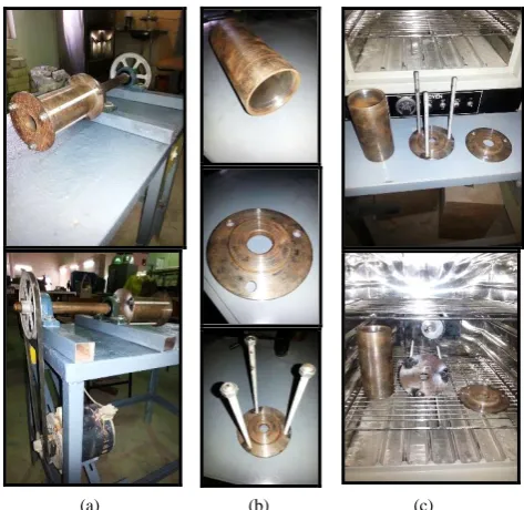
3. 1. Fabrication of the Vertical Centrifugal Casting Machines The fabricated of the vertical centrifugal casting machines can be used also as
precision plaster-mold lost wax process for special applications, including for cams, jewelry, locks, bushings, medals, figurines, keys, and dental castings. The fabricated vertical casting machine as shown in Figure (1a) was consists of a two speeds electric motor (950 and 1420 RPM) and a rotor head capable to holding the centrifugal casting mold rigidly during rotation without any unappreciable vibration. The fabricated centrifugal rotor head and the plaster-mold lost wax were fitted on the central shaft. The circular table with a diameter of 500 mm, which is larger than the mold diameter, was fabricated to mounting the mold and saving the operators during the mold spinning. The central shaft which is mounting by two-bracket type bearings and obtained its rotating speeds from the electric motor through a set of driver and driven pulleys and a V-belt.
The fabricated molds for the vertical machine were made by mixing the white gypsum plaster (CaSO4) fine powder with water to gets a clay-like consistency, which can be shaped around the wax pattern to obtained thinner sections, very good surface finish, and dimensional accuracy. The mold was backed in a thin steel tube of a diameter = 45 mm to strengthening the gypsum plaster pattern. The fabricated centrifugal rotor head and the plaster-mold lost wax are shown in Figure (1b). To melt and remove the wax pattern, the mold then inverted and dried in a low-temperature oven.
However, gypsum plaster method is mainly used for non-ferrous metals of lower-melting-point like zinc, copper, aluminum, and magnesium as it is relatively soft at a temperature above 1200°C. The fabricated machine can also be also used for ferrous metals of high-melting-point like steel, stainless steel, alloy steel, and superalloys by using the ceramic mold material instead of plaster.
The casting cools slowly as the plaster has a lower thermal conductivity, and therefore more uniform grain structures were obtained, with less warpage and residual stresses.
The main selected centrifugal casting parameters to achieve the objectives of this work are the mold rotation speeds, the pouring temperature, the mold initial preheated temperature prior to pouring, the centrifugal force and the spinning period time as illustrated in the Table 1. Other designed parametric values can be obtained as mentioned later.
In this work, the selected hypoeutectic aluminum silicone (AlSi) alloys mainly used for casting pistons for internal combustion engines. Significant structural changes were occurred during the piston’s operation, lead to a reduction of mechanical properties [19]. At elevated temperatures up to 240°C, this alloy offers a high tensile strength [20].
(a) (b)
Figure 1. (a) The fabricated precision plaster-mold lost
wax vertical centrifugal casting machine; (b) The fabricated centrifugal rotor head and the plaster-mold lost wax
TABLE 1. The values of the selected vertical centrifugal
casting parameters.
Item No. Parameter Designed values
1 The mold rotation speeds (RPM) 0, 350, 520, 690, 820
2 The pouring temperature (oC) 770
3 Mold initial preheated
temperature prior to pouring 180
4 Centrifugal force (N) 0, 4.21, 10.64, 10.09, 16.81
5 The spinning period of time
(min.) 5
6 The G factor 0, 25.04, 50.18, 87.99, 125.24
graphite crucible. For increasing the fluidity of the molten metal, the plaster molds for the vertical machines experimental group were preheated at 180 °C at an electric oven type ILE India as shown in Figure (2a). Then the melted metal was poured into the cavity of the fabricated centrifugal rotor head plaster-mold as shown in Figure (2b), which was rotated immediately until solidification of all the poured metal. In gravity casting, the same procedures were used, but the mold was kept stationary.
3. 2. Fabricating the Horizontal Centrifugal Casting Machine The fabricated horizontal centrifugal casting shown in Figure (3a) was mainly contained with same components of the vertical casting machine except that the cylindrical rotating mold was contained from a cylindrical steel mold and two end flanges fixed by three M14 bolts as shown in Figure (3b). A steel pouring device was fabricated for pouring
the melting metal in the mold. The opening end of the cylindrical mold was exposed to receive the pouring melting metal and the closed-end was coaxially connected to the central rotating shaft with the designed variable speeds as 405, 690, 950, 1230 and 1420 RPM. The cylindrical drum mold was fabricated from mild steel with a length of 172mm, inner diameter of 75 mm and a total weight of 4.161 Kg. The workpiece outer diameter is 75, the inner diameter of 69 and a length of 172 mm. The produced AlSi cylindrical workpiece weight is about 315 g and the workpiece volume is about 116.72 cm3. Table 2 illustrates the main selected horizontal centrifugal casting parameters.
The selected material was melted in a graphite crucible at a temperature of 770°C by using an electrical furnace. The mold was preheated at 180 °C using an electric oven, as shown in Figure (3c).
(a) (b)
Figure 2. (a) The electric oven type ILE India for preheated
the plaster molds; (b) The fabricated centrifugal rotor head plaster-mold cavity
(a) (b) (c)
Figure 3. (a) The fabricated horizontal centrifugal casting
TABLE 2. The selected horizontal centrifugal casting parameters.
Item
No. Parameter Designed values
1 The mold rotation speeds (RPM) 0, 405, 678, 950, 1230, 1420
2 The pouring temperature (oC) 740
3 The mold initial preheated
temperature prior to pouring (oC) 180
4 Centrifugal force (N) 20.48, 58.70, 112.14. 188.38, 250.45
6 The spinning period of time (min.) 5
7 The G factor 6.63, 18.20, 36.29,
60.96, 81.05
4. RESULTS AND DISCUSSIONS
After examined for chemical compositions, the main contains SiAl alloy workpiece material were; 10.5 % Si and 2.69 % Cu. The examined alloy is a hypoeutectic aluminum silicone alloy contains less than 12% Si. The two important alloying elements, i.e. Si and Cu are added to Al-Si cast alloys to increase the strength at room and elevated temperature and to make the alloy heat-treatable. Silicone is responsible for good castability, but the more Si contains gives the lower coefficient of thermal expansion. Si is a very hard phase; thus, it contributes to wear resistance. Cu was improving the creep resistance and increasing the strength at elevated temperatures (up to ~200 ºC) [21]. These aluminum alloys have different intermetallic phases and the distribution and morphology of each phase have important roles in mechanical properties on the material [22]. These alloys are used for compressor cases, timing gears, rocker arms, engine cooling fans, crankcases, air compressor pistons, structural aerospace components, etc. [23-25].
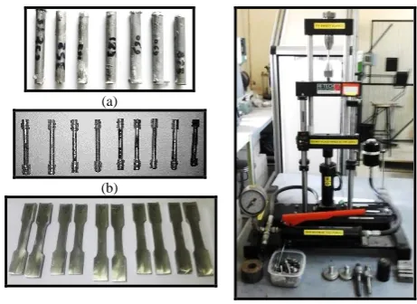
Figures (4a and 4b) show the fabricated vertical centrifugal casting workpieces (which are designed as a tensile test specimen) at different mold rotation speeds before and after turning by the universal turning machine, respectively. Two workpieces were fabricated and tensile tested for each designed mold speed value to the final dimensions of 65x10 mm, that suitable to Hi-Tech (50 kN capacity) tensile testing machine with initial testing length equal to 40mm, and a diameter of 6.5 mm (the cross-sectional area = 33.183 mm2). The average tests results are given in Table 3. Figure (4c) shows the fabricated horizontal centrifugal casting tensile tests specimens at different mold rotation. These tests were implemented on the Instron universal testing machine of 1200 kN capacity.
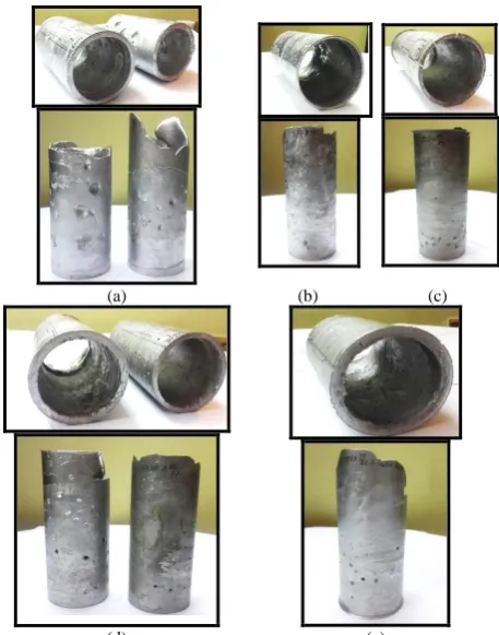
Figures (5a to 5e) show the fabricated horizontal centrifugal casting AlSi hypoeutectic alloy tubes at all
(a)
(b)
(c) (d)
Figure 4. (a) The fabricated vertical centrifugal casting tensile
testing specimens at different mold rotation speeds before turning; (b) after turning; (c) The fabricated horizontal centrifugal casting tensile tests specimens at different mold rotation speeds; (d) The Hi-Tech (50 kN capacity) tensile testing machine
the designed mold rotation speeds. Figure (5a) shows the fabricated two pipes using the mold rotation speed of 407 RPM. The first pipe was fabricated without pre-heating of the used mold (the upper right figure and the lower on the left), while the second pipe was fabricated after pre-heating of the mold in an electric oven to 180°. The proper portion of the first pipe length is 90 mm, i.e. 52% of the total mold length which is equal to 172 mm, while this proper length improved in the second pipe reached 115 mm or 60% of the mold length. This was because of the decreased in the coefficient of friction between poured cast metal and the inner surface of the mold. The produced pipe thickness reached 6.25 mm. At the inner surface of the first pipe, three big raining defects were noted with a diameter of 8-9 mm and a depth of about 2 mm, while only one raining defects were noted in the second pipe with a diameter of 9 mm and depth of about 2 mm. These defects were caused because when the reducing in casting speed results in decreasing the solidification temperature of the inner layers of the molten metal [26].
At the beginning of the first pipe, a linear segregation defects on the outer surface were also observed with a width of 1-1.5 mm and depth of 0.8 mm peripherally directed 10° to the left and other one was noted at the pipe end with the same dimensional and peripherally directed 45° to the right, while at the second pipe less depth, up to 0.7 mm of linear segregation defects were observed at the beginning and the end, at an angle of 25° to the left, due to the insufficient relative motion of SiC particles. These segregations of primary phase were filling by the remaining melt [27].
Figure (5b) shows the fabricated pipes using the mold rotation speed of 690 RPM. An increase in the proper length of the pipe to 153 mm or 89% of the total mold and the thickness of the pipe was 3.3 mm with a smaller number of the shrinkage cavities on the outer surface of the pipe with a diameter less than 3.5 to 5 mm and a depth of 0.6 to 1.8 mm were observed. There are a smaller spaced shrinkage cavity and pores that also found on the outer surfaces, but with lower sizes than the previously fabricated pipes, while no defects were observed on the inner surface of the pipe except a spaced porous.
Figure (5c) shows the fabricated pipe at the mold rotation speed of 950 RPM. It has been observed that the proper length of this pipe reached 150 mm or 87% of the total mold length, and the pipe thickness of 4 mm and more uniformity in thickness variations were achieved [28]. A decrease in the quantity and size of shrinkage cavities on the outer surface of the produced pipe were observed. Only three cavities were seen with an average diameter up to 3-4 mm and a depth of up to 1.2 mm with others that owned lower depths and diameters. A porous with small dimensions were noted in general.
Figure (5d) shows the fabricated two pipes when the mold rotation speed was 1230 RPM. The proper length of the first pipe (at the left figure) was 125 mm or 73% of the total mold length, as the mold was preheated at only 100°, while the second mold was preheated to 180°, and it has been observed that the proper length of the second pipe produced increased to 145 mm or 84% of the total mold length. It was observed that the shrinkage cavities were less than previously fabricated pipes with diameters of about 5 mm and a depth of 2 mm for the first pipe and about 3 mm and a depth of about1 mm for the second pipe. On the outer surface of the first pipe, a linear peripheral segregation defect was observed with small sizes and a number of porous were noted in general, while a lowest and smallest porous were observed in the second pipe.
Figure (5e) shows the fabricated pipe using the mold rotation speed of 1420. It has been observed that the proper length of the produced pipe was 110 mm or 64% of the total mold length, where an increased in the
(a) (b) (c)
(d) (e)
Figure 5. The fabricated AlSi hypoeutectic alloy tubes
produced by the horizontal centrifugal casting machine; (a) at mold rotation speed 405 RPM; (b) at mold rotation speed 690 RPM; (c) at mold rotation speed 950 RPM; (d) at mold rotation speed 1230 RPM; (e) at mold rotation speed 1420 RPM;
diameter of shrinkage cavities defects up to 5 mm but with a less in-depth up to 1.5 mm were observed. A very few porosities were noted on the pipe outer surface, while the inner surface almost seen without defects.
centrifugal casting processes are given in Tables 3 and (4), respectively.
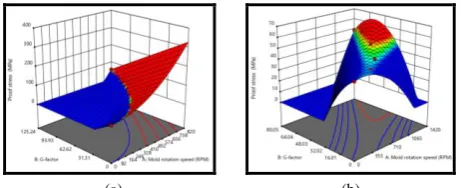
The 3D plots Figures (6a and 6b) show the effects of vertical and horizontal mold rotation speeds and G-factors values on the proof stresses (2% of the final length), respectively. These figures show that the proof stress values were increased with increasing the mold rotation speed up to (690 RPM) and G- factor value of 87.99. For vertical casting experiments reached the maximum value of (59.10 MPa) as shown in Figure (6a), while for gravitational casting (i.e. without mold rotation speed), this value reached (55.40 MPa). This means an increase in proof stress by (6.7%) due to the increase of the used centrifugal force acting on the poured metal
This will lead to squeezing and compact the poured metal particles during solidification and to increase the alloy strength and density and thus to produced castings with fewer defects or shrinkage cavities. This percentage benefited value will be increased when using a larger mass of the produced workpieces. Figure (6b) shows the effects of the same process parameters on the proof stresses (2% of the final length) during the horizontal casting experiments, which was reached it is maximum value at mold rotation speed up to (1230 RPM) and a value of G-factor = 60.96, which means
TABLE 3. The effects of the vertical centrifugal casting mold
rotation speeds and G-factors on the mechanical properties of AlSi alloy workpieces
No. Mold rotation
speed (RPM) G-factor
Proof stress (MPa)
Tensile strength
(MPa)
Elongation (%)
1 0 0 55.40 116.22 0.375
2 350 23.04 56.70 144.76 0.317
3 520 50.18 57.82 171.43 0.305
4 690 87.99 59.10 189.45 0.281
5 820 125.24 57.90 174.11 0.295
TABLE 4. The effects of the horizontal centrifugal casting
mold rotation speeds and G-factors on the mechanical properties of AlSi alloy workpieces pipes
No. Mold rotation
speed (RPM) G-factor
Proof stress (MPa)
Tensile strength
(MPa)
Elongation (%)
1 0 0 44.41 102.46 0.426
2 405 6.63 45.53 122.89 0.393
3 690 18.20 47.12 136.04 0.359
4 950 36.29 51.70 163.31 0.333
5 1230 60.96 53.57 187.69 0.291
6 1420 80.05 48.74 167.64 0.314
agreeing with what Boljanovic [18] found that the G-factor is more than 50), reached (53.57 MPa), which is higher by 20.62 % compared with the gravitational casting. This was the best value obtained and the material reached the best compression and compaction actions of the cast metal particles during solidification. These proof stresses values will be decreased with increased the molding speed or the centrifugal force for both vertical or horizontal centrifugal casting processes due to excessive in speed, that leads to reduce the strength of the produced alloys and to introduce the segregating defects on the crystalline structure grain boundaries.
Figures (7 a and 7b) show the effects of vertical and horizontal centrifugal mold rotation speeds and G-factors values on the tensile strength values for the ex- mined workpieces, respectively.
For the vertical centrifugal casting experiments, the highest tensile strength was obtained when working with die speed of (690 RPM) and (G-factor = 88), while Boljanovic [18] found that the G-factor required between 60 to 80 for the vertical centrifugal casting, reached (189.45 MPa) as shown in Figure (7a).
This value is higher by (38.66 %), compared with the gravitational casting result, which is (116.22 MPa), while Chirita et al. [30] have identified this value as 225 MPa and 178 MPa for vertical centrifugal and gravitational casting, respectively, which means achieving a benefit by 20.9 % when they worked on an aluminium alloy AS12UN [29], and when used Al–Si alloys containing 18% weight of Silicon achieving a benefit by 14.4 %. Figure (7b) shows that for the horizontal centrifugal casting experiments, the highest tensile strength was reached when working with the mold rotation speed of (1230 RPM) and (G-factor = 60.96), reached (187.69 MPa), which is higher by (45.41 %), compared with the gravitational casting result as (102.46 MPa), while Prashantha et al. [34] have identified this value as 163 MPa when they worked on Al–Si alloys containing 12% weight of
(a) (b)
Figure 6. The 3D plots of the effects of centrifugal mold
Silicon and as178 MPa for the work done by Shailesh et al. [31] used an Al-Si alloy (4600).
Figures (8a and 8b) show the effects of centrifugal mold rotation speeds and G-factors values on the percentage elongation of the produced specimens. The results show that the percentage elongation decreased with increasing the mold speed and G-factors. For the vertical centrifugal casting experiments, the lower percentage elongation obtained when the mold speed running at (690 RPM) and the obtained value of G-factor = 88, where the elongation reduced to (0.281%), i.e. decreased by (33.45 %) compared with the value obtained for gravitational casting, while Prashantha et al. [32] have identified this value as 0.44 % when they worked on Al–Si alloys containing 12% weight of Silicon. Then the elongation percentage begin to increase again with increasing the molding speed and centrifugal force as shown in Figure (8a). Chirita et al. [30] have been reduced the elongation percentage for vertical centrifugal to 28% compared with gravitational casting when they worked on an aluminium alloy AS12UN [29], and when used Al–Si alloys containing 18% weight of Silicon achieving 40.8 %.
(a) (b)
Figure 7. The 3D plots of the effects of centrifugal mold
rotation speeds and the G-factors on tensile strength values; (a) for the fabricated vertical centrifugal casting machine tests, and (b) for the fabricated horizontal centrifugal casting machine tests
(a) (b)
Figure 8. The 3D plots of the effects of centrifugal mold
rotation speeds and the G-factors on percentage elongation values; (a) for the fabricated vertical centrifugal casting machine tests, and (b) for the fabricated horizontal centrifugal casting machine tests
Figure (8b) shows that for the horizontal centrifugal casting experiments, the lower percentage elongation obtained when the mold rotation speed running at (1230 RPM) and (G-factor = 60.96), reached (0.291 %), which is lower by (31.69 %), compared with the gravitational casting result.
5. CONCLUSIONS
After studying and examining the quality of the producing workpieces, the following conclusions and can be conducted:
1. The obtained results show that the proof stress values were increased with increasing the mold rotation speed up to (690 RPM) and (1230 RPM) and G- factor value up to 87.99 and 60.96 for vertical and horizontal casting experiments reached the maximum value of (59.10 and 53.57 MPa), respectively. This means an increase in proof stress by (6.7%) and (20.62) % compared with gravitational casting, respectively.
2. The same effects of the vertical and horizontal centrifugal input parameters were existing on the tensile strength values on the examined workpieces, respectively. The highest tensile strength was obtained when working with the same mold speeds and G-factor, reached (189.45 and 187.69 MPa), which is higher by (38.6 and 45.41 %), compared with the gravitational casting, respectively.
3. The results show that the percentage elongation decreased with increasing the mold speed and G-factors. For the vertical and horizontal centrifugal casting experiments, the lower percentage elongation obtained when the molding speed running at (690 RPM) and the value of G-factor = 88, reduced to (0.281and 0.291 %), which was decreased by (33.45 and 31.69 %) compared with the values obtained for gravitational casting experiments, respectively.
4. For the vertical and horizontal produced workpieces, the outer surfaces obtained with the finest surfaces quality and less defects when working at mold rotation speed (520 to 690) and (950 to 1230 RPM), i.e., when the values of the G-factor approximately between (50.18 to 87.99) and (36.29 to 60.69), and with an average of about (G = 69 and 50, which can be considered as the best value, i.e. the centrifugal force obtained of seventy and fifty times the force of gravity, respectively.
6. REFERENCES
1. Oyewole, A. and Sunday, A.M., "Design and fabrication of a centrifugal casting machine", International Journal of Engineering Science and Technology, Vol. 3, No. 11, (2011). 2. Zagorski, R. and Sleziona, J., "Pouring mould during centrifugal
casting process", Archives of Materials Science and Engineering, Vol. 28, No. 7, (2007), 441-444.
3. Song, N.N., Wu, S.P., Kang, X.H. and Li, D.Z., "Hydraulic experiments of mold filling process in horizontal centrifugal casting", in Advanced Materials Research, Trans Tech Publ. Vol. 154, (2011), 314-320.
4. Kim, K., Lim, J., Jang, S., Park, E., Joo, J., Hong, G.-W., Kim, C.-J., Kim, H.-R. and Hyun, O.-B., "Fabrication and characterization of bscco-2212 tube prepared by centrifugal casting", Physica C: Superconductivity and its Applications, Vol. 463, (2007), 460-463.
5. Ali, S.M., "The effect of reinforced sic on the mechanical properties of the fabricated hypoeutectic al-si alloy by centrifugal casting", Engineering Science and Technology, an International Journal, Vol. 22, No. 4, (2019), 1125-1135. 6. Madhusudhan, S.N., Kumar, G. and Mukunda, P.,
"Experimental study on rate of solidification of centrifugal casting", International Journal of Mechanical and Materials Engineering, Vol. 5, No. 1, (2010).
7. Kim, M.G., Sung, S.Y., Lee, G.C., Park, J.P. and Kim, Y.J., "Investment casting of near-net shape gamma titanium aluminide automotive turbocharger rotor", in Materials Science Forum, Trans Tech Publ. Vol. 475, (2005), 2547-2550.
8. Yuan, H., Wan, C., Yiling, L., Bu, Y. and Ge, L., "The research on the biggest borehole curvature that allowed through for the rotating casing (research note)", International Journal of Engineering, Vol. 28, No. 3, (2015), 483-489.
9. El-Galy, I., Ahmed, M. and Bassiouny, B., "Characterization of functionally graded al-sicp metal matrix composites manufactured by centrifugal casting", Alexandria Engineering Journal, Vol. 56, No. 4, (2017), 371-381.
10. Radhika, N., Thirumalini, S. and Jojith, R., "Development and properties of centrifugally cast silicon nitride reinforced functionally graded copper matrix composite", Silicon, Vol., No., (2019), 1-14.
11. Daming, X., Qingmei, Y., Xin, L. and Geying, A., "Mold filling behavior of melts with different viscosity under centrifugal force field", Journal of Materials Sciences and Technology, Vol. 18, No. 02, (2009), 149-151.
12. Madhusudhan, N.S. and Kumar, G.M., "Properties of centrifugal casting at different rotational speeds of the die", International Journal of Emerging Technology and Advanced Engineering, Vol. 3, No. 1, (2013), 727-731.
13. Mukunda, P. and Rao, A.S., An understanding of fluid behavior in centrifugal casting. 2007, AFT/TFI-2007, Commemoration of the 100th Anniversary of Tohoku University ….
14. Mohamad, N.N., Muhamad, N., Jamaludin, K., Ahmad, S. and Ibrahim, M., "Flow behaviour to determine the defects of green part in metal injection molding", International Journal of Mechanical and Materials Engineering, Vol. 4, No. 1, (2009), 70-75.
15. Shailesh, P., Kumar, B.P., Sundarrajan, S. and Komariahia, M., "Experimental investigation on centrifugal casting of 5500 alloy: A taguchi approach", Scientific Research and Essays, Vol. 7, No. 44, (2012), 3797-3808.
16. Royer, A. and Vasseur, S., "Centrifugal casting", ASM Handbook., Vol. 15, (1988), 296-307.
17. Shigley, J.E., "Shigley's mechanical engineering design, Tata McGraw-Hill Education, (2011).
18. Boljanovic, V., "Metal shaping processes: Casting and molding, particulate processing, deformation processes, and metal removal, Industrial Press Inc., (2010).
19. FEJÉR, E. and VARGA, B., "The analysis of eutectical al-si alloys properties used for piston cast in the internal combustion",
Scientific Bulletin of'Valahia'University. Materials & Mechanics, Vol. 12, No. 9, (2014), 43-48.
20. Lee, J.A., "Cast aluminum alloy for high temperature applications", Automotive Alloys, The Minerals, Metals & Materials Society, (2003).
21. Stadler, F., Antrekowitsch, H., Fragner, W., Kaufmann, H. and Uggowitzer, P.J., "Effect of main alloying elements on strength of al–si foundry alloys at elevated temperatures", International Journal of Cast Metals Research, Vol. 25, No. 4, (2012), 215-224.
22. Azadi, M., Rezanezhad, S. and Zolfaghari, M., "Effects of various ageing heat treatments on microstructural features and hardness of piston aluminum alloy", International Journal of Engineering, Vol. 32, No. 1, (2019), 92-98.
23. Stadler, F., Antrekowitsch, H., Fragner, W., Kaufmann, H., Pinatel, E. and Uggowitzer, P.J., "The effect of main alloying elements on the physical properties of al–si foundry alloys",
Materials Science and Engineering: A, Vol. 560, No., (2013), 481-491.
24. Olofsson, J., Svensson, I.L., Lava, P. and Debruyne, D., "Characterisation and investigation of local variations in mechanical behaviour in cast aluminium using gradient solidification, digital image correlation and finite element simulation", Materials & Design, Vol. 56, (2014), 755-762. 25. Carvalheira, P. and Gonçalves, P., "Fea of two engine pistons
made of aluminium cast alloy a390 and ductile iron 65-45-12 under service conditions", in 5th International Conference on Mechanics and Materials in Design Porto-Portugal., (2006), 24-26.
26. Jabari Moghadam, A. and Hosseinzadeh, H., "Thermal simulation of solidification process in continuous casting",
International Journal of Engineering Transactions B: Applications, Vol. 28, No. 5 (2015), 812-821.
27. Wang, K., Zhang, Z., Yu, T., He, N. and Zhu, Z., "The transfer behavior in centrifugal casting of sicp/al composites", Journal of Materials Processing Technology, Vol. 242, (2017), 60-67. 28. Tabatabaei, S.M. and Alasvand Zarasvand, K., "Investigating the
effects of cold bulge forming speed on thickness variation and mechanical properties of aluminum alloys: Experimental and numerical", International Journal of Engineering Transaction C: Aspects,, Vol. 31, No. 9, (2018), 1602-1608.
29. Chirita, G., Soares, D. and Silva, F., "Advantages of the centrifugal casting technique for the production of structural components with al–si alloys", Materials & Design, Vol. 29, No. 1, (2008), 20-27.
30. Chirita, G., Stefanescu, I., Cruz, D., Soares, D. and Silva, F., "Sensitivity of different al–si alloys to centrifugal casting effect", Materials & Design, Vol. 31, No. 6, (2010), 2867-2877. 31. Shailesh, P., Sundarrajan, S. and Komaraiah, M., "Optimization of process parameters of al-si alloy by centrifugal casting technique using taguchi design of experiments", Procedia Materials Science, Vol. 6, No., (2014), 812-820.
Optimization of Centrifugal Casting Parameters of AlSi Alloy by using the Response
Surface Methodology
S. Mahmood Ali
Biomedical Engineering Department, University of Technology, Iraq
P A P E R I N F O
Paper history:
Received 23 July 2019
Received in revised form 6 September 2019 Accepted 12 September 2019
Keywords:
Horizontal and Vertical Centrifugal Casting Response Surface Methodology
Hypoeutectic AlSi Alloy Design of Experiments G- factor and Mold Rotation Speed
هديكچ ر ی هتخ رگ ی رتناس ی ف ی و ژ ی ک ی اه هخاش زا ی پ ی هتفرش ر ی هتخ رگ ی ژرولاتم تعنص رد هدرتسگ روط هب هک تسا ی هدافتسا دروم م رارق ی گ ی در ن نآ رد و ی ور ی رگ ی ز وقت هب زکرم زا ی
ت م کمک راک هعطق هدام ی
سررب روظنم هب رضاح راک شلات .دنک ی ثأت ی ر اهرتماراپ ی ر ی هتخ رگ ی رگ ی ز قفا زکرم زا ی دومع و ی رچ تعرس لماش خ
رگ بلاق ش ی ز داقم و زکرم زا ی ر G- رررب اهروتکاف ک ی ف ی ت ا .تسا لوصحم ی
ن حارط اب راک ی اه هنومن تخاس و ی ر ی هتخ رگ ی رگ ی ز قفا زکرم زا ی دومع و ی زه مک ی هن زاوررل اب بناج ی لصا ی ارب ی لوت ی د اه هنومن ی مولآ ین ی و س یل ی نوک ه ی تووپ ی تک ی ک سلآ ی (AlSi) اوتحم ی 10 ٪ Si اپ هب ی نا سر ی هد تسا . اتن ی ج برجت ی پماک همانرب زا هدافتسا اب ی
رتو ی رامآ ی "Expert Design 11" خساپ حطس شور و
(RSM) زجت ی ه لحت و ی ل دوبهب و ی هتفا اتن .تسا ی ج ارب هک داد ناشن ی آرف ی اهدن ی ر ی هتخ رگ ی دومع ی قفا و ی رتهب ، ی ن ک ی ف ی ت اررب راررک اررگنه حوطس
زا بلاق شخرچ تعرس 520 ات 690 و 950 ات 1230 RPM ، دمآ تسدب ی نع ی م اب ی گنا ی ن م ی گنا ی ن روتکاررف 69 و 50 ترت هب ی ب داقم ی ر ازفا اب تابثا شنت ی
ش ( ات بلاق شخرچ تعرس 690
قد رد رود ی هق ( و ) 1230 قد رد رود ی هق ازفا ) ی ش ی هررتفا یا رادقم زا G- روتکاف 87.99 و هدش هدافتسا 96 . 60 % ازفا ی ش اررب ار شنررت تمواقم 7 . 6 و 6 . 20 % ررفا ز ای ش .تررسا هداد ارب ی امزآ ی ش اه ی ر ی هتخ رگ ی دومع ی قفا و ی ترت هب ی ب ر اب ی هتخ رگ ی شنارگ ی داقم . ی ر ششک اکحتسا ی
رد هدررمآ تسد هب
اقم ی هس ر اب ی هتخ رگ ی شنارگ ی ترت هب ی ب اب 6 . 38 و 41 . 45 % دوبهب ی هتفا لاح رد ، تسا ی
ررشک دررصرد هک ی گد ی د دررصر هررب 281 0. و 0.291 % شهاک ی هتفا ا ، تسا ی ن نعم نادب ی هک تسا ترت هب ی ب ارب ی 0 . 45 و 33 . 31 % ارررب ی دوررمع ی شهاررک ی هتفا ر و .تسا ی هتخ رگ ی رگ ی ز قفا زکرم زا ی اقم رد ی هس داقم اب ی ر امزآ طسوت هدمآ تسد هب ی ش اه ی ر ی هتخ رگ ی شنارگ ی .