٭
Corresponding Author, Email: [email protected]
The Transient Behavior of LC and Ring Oscillators
under External Frequency Injection
A. Tofangdarzade
1٭and A. Jalali
21-PhD Student, Electrical Department of Shahid Beheshti University, Tehran, Iran 2-Assistant professor, Electrical Department of Shahid Beheshti University, Tehran, Iran
ABSTRACT
In this work, time domain analysis is used to solve Adler’s equation in order to obtain the required time,
for an oscillator under external injection, reaching the steady-state condition. Mathematical approach has
been applied to fully describe the transient of frequency acquisition in injection-locked LC and Ring
oscillators considering their time-varying nature. Then, the analysis is verified by simulations of a ring as
well as a typical RF-LC oscillator. Likewise, the effect of initial phase difference of injection signal on
locking time and phase noise is theoretically studied. For Ring oscillators, a delay-based time–domain and
perturbation analysis are used to reveal the dependency of circuit parameters to the locking time. Finally, the
design insights are deduced which enable the designers to evaluate and minimize the timing budget required
to achieve injection locking in designing a fast locking oscillator. The mathematical consequences in this
work explain why there is no transient behavior while ring oscillator signal propagates from a stage to
another, or why the initial phase shift of injection signal has no effect on the phase noise of oscillator.
KEYWORDS
Amirkabir International Journal of Science& Research (Electrical & Electronics Engineering)
(AIJ-EEE)
A. Tofangdarzade and A. Jalali
36 Vol. 46, No. 2, Fall 2014 1- INTRODUCTION
A free-running oscillator can be influenced by the frequency of an externally injected oscillator. If certain conditions are satisfied, the injected frequency could take over the free-running frequency of the oscillator. This process is called Injection Locking which has been thoroughly analyzed in [1]-[5] and widely used in modern analog electronics for many applications such as frequency division [6]-[8], multiplication [9], quantization noise reduction in synthesizers [10], stability and phase noise reduction [11]-[15].
There is a time interval required for the original oscillator to adjust its frequency according to the injected frequency [3]. This time interval is called locking time, tLock. Reference [3] defines this time in a special case for
the high level injection. And also in [2], a definition and analysis are presented to locking time in microwave oscillators. Since the equation obtained for phase is very unwieldy and complicated, the numerical methods are used in mentioned references to depict locking time related curves.
In recent years, because of shorter settling times (in the order of nanoseconds) required for UWB PLL-based synthesizers or any fast frequency-hopped systems, the significance of locking time of injection locked oscillators has been grown considerably [16]-[19]. As a result, some careful attempts have been done to describe the injection locking transient which clarifies the time varying nature of LC-oscillator responding to external injections [16]. Unfortunately, there is no analysis about Ring oscillators as well as phase noise in this work. Besides, there are other approaches that have defined a time constant for oscillator settling time after externally injection locked using perturbation theory [20]-[22]. Although this approach accurately describes the effective parameters in time domain steady state response, it ignores the time varying (LTV) nature of oscillator.
Therefore, in this work, based on the phase-domain analysis presented by Adler [1], a closed-form relationship is obtained for the locking time improving our previous work, [23], by taking into account the time varying nature of oscillator. In fact, the main focus of this work is the complete study for the transient behavior of Injection-locked LC and Ring oscillators including the effect of settling time on phase noise. Both time domain and perturbation theory are used to fully describe the settling process. So, at first, the LC oscillators are analyzed and the findings, which match the conclusions of [16], are expanded to understand the process in ring oscillators. However, since Adler-equation-based approach is highly dependent on Q, the oscillator quality factor, it may not be suitable in describing the relationship between the circuit parameters and the locking time for a ring oscillator. Hence, to get around the abovementioned problem, a time-domain delay-based model proposed in [24] is utilized to relate the circuit parameters with the locking time. Then, using Generalized-Adler equation and perturbation theory, the
phase noise of oscillators are analyzed. In fact, using this method, not only the phase noise is extracted in more intuitive manner, but also the transient governing the phase noise in the oscillators under external frequency injection is described exactly.
The paper is organized as follows. In section I, the theoretic basis required for time-domain or perturbation theory is discussed. Section II and III introduce the study of transient behavior of injection locked LC and Ring oscillators, respectively. Section IV includes Phase noise analysis, and in Section V simulation results are presented. Finally, the conclusion section summarizes the most important results of this paper.
2-REQUIRED BACKGROUND FOR INJECTION LOCKING EQUATIONS
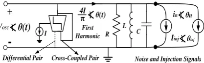
The main purpose of injection locking is to influence an oscillator with over another one. Fig. 1 is introduced as a basic model for transient behavior study or phase noise analysis in LC and Ring oscillators under external frequency injection which sums up the most important outlooks in this area throughout the literature [20]-[22]. In this figure, a conventional LC-cross-coupled oscillator equivalent circuit under external frequency injection (Iinj) is shown. Noise current source in in the model indicates the resultant white noise injected to the output node of oscillator. The cross-coupled transistor pair of the oscillator is modeled with the voltage-to-current transconductor which commutates tail current I. So, the Fourier series expansion can be used to extract the current incoming to the Tank. Only the main harmonic is sustained through the band pass filtering nature of the Tank. The dashed line in transconductor shown in the figure is related to the equivalent model for conventional differential pair (not cross-coupled) used in gain stages of ring-type oscillators.
R L
C
Iinj θinj
in θn
VOSC
θ(t)
I-+
4I θ(t)π
Differential Pair Cross-Coupled Pair First Harmonic
Noise and Injection Signals
Fig. 1. Equivalent circuit of LC or Ring oscillator including white-noise source and Injection current. Dashed line with the zero inductance L is related to one stage of a ring oscillator
Therefore, employing the dashed path, and eliminating the inductor L, one stage of a ring oscillator equivalent circuit is resulted like [22]. Thus, Fig. 1 includes all the necessary subjects for our study.
) sin(
) sin( 2
0
0 0
L inj
osc inj inj
I I Q dt
d
(1)
where ωL is the lock range. This means that, if the distance between injected and primary frequency, called detuning, is smaller than ωL, the injected frequency falls within the lock range and injection locking can occur. Note that, (1) is derived with the assumption of small detuning, ω0 – ωinj, and small injection strength, ρ =
Iinj/Iosc. This concept can be shown mathematically as below:
0 L inj 0 L
(2)An equivalent form of Adler equation has also been derived in which by using the variable substitution θ → θ
- θinj , it changes to the previous form (eqn. (1)) [11]-[15]. Both forms which can be helpful for different types of analysis will be applied in this work.
0
0
sin (
)
2
inj
inj osc
I
d
dt
Q I
(3)When dθ/dt goes to zero, locking will happen. Under this condition, equation (1) specifies that the instantaneous frequency becomes the same as the injected frequency. After locking has occurred, the compensating phase shift φss, which has a non-zero value for non-zero detuning, can be determined as below:
1 0
sin [(
)
]
ss inj L
(4)
Two useful approaches can be considered. First, the perturbation method is employed for the examination of system characteristics near the locking. It means that, by assuming θinj = ωinj t + φss in which φss is the constant phase shift because of injection signal, and θ = ωinjt +
ˆ
, where,
ˆ
is the phase small fluctuations, then substituting into equation (3), the following equation is resulted:
0ˆ
1
ˆ
ˆ
2
inj
I
d
Cos
dt
Q I
(5)Where,
0
1
2Q Cos
(6)that τθ is phase-stability time-constant of the oscillator
response to the external injection. Differential equation (5) can be solved analytically with the following answer:
ˆ ˆ 0 exp t
t
(7)
Where,
ˆ 0
is the integration constant which contains the effect of initial phase shift of injection signal on the phase fluctuations. Now, the system approaches lockingwhile
ˆ
goes to zero and the time that this event happens can be assumed as the locking time. Therefore, study of locking time can be categorized into two independent factors, which are:1) time-constant τθ that is permanent for every initial condition and determines the system agility to accept the injected signal. In fact, this factor represents the time-invariant approach (LTI model) for an oscillator. The larger the time-constant, the longer is the locking time. Therefore, with small quality factor, larger injection strength, or injecting as near as possible to the free-running frequency of oscillator, the locking time becomes shorter.
2)
ˆ 0
, which shows the initial phase difference between injection and free-running signals. In other words, the time of applying an injection signal can be important for the system stability due to time varying nature of oscillator (LTV model). However, two things are required to be considered. First, this initial condition is extracted assuming near-locking condition for oscillator, so
ˆ 0
is very small in this condition, and also in the injection instant, it can be greater in comparison with the locking instant, so the limitation of small fluctuations of phase for perturbation analysis could not be satisfied. Second, there is no information about the phase fluctuations near or far from the locking and this parameter is only a random small fluctuation. So, another analysis is necessary to find the effect of initial phase shift of injection signal. Since we are interested in a special period of time, it seems logical to use time-domain analysis which is the subject of next section.3- TIME DOMAIN ANALYSIS OF ADLER EQUATION
In previous section, a perturbation analysis shows that the initial condition of signal injection is also important in locking time study. In this section, time-domain analysis is employed to portrait this effect. Again, we return to the Adler equation (1), and using the variable substitution, u = tan(θ/2), and the trigonometric relationships below, this equation can be solved.
)) 2 ( tan 1 ( ) 2 tan( 2 )
sin(
2
(8)2
1 2
u dt du dt d
(9)
Amirkabir International Journal of Science& Research (Electrical & Electronics Engineering)
(AIJ-EEE)
A. Tofangdarzade, A. Jalali
38 Vol. 46, No. 2, Fall 2014
dt u u du dt d L L 1 2 2 sin 0 2 0 0
(10)In (10), the denominator can be solved resulting in two potential distinct roots. Variation of θ or u tends to be zero in the vicinity of both denominator roots. Then, θ goes to φss, or equivalently the parameter u goes to
tan(φss/2) in this state. Therefore, both of the roots are demonstrating the steady-state phase shift. But, what is the deference between roots? In order to reveal the discrepancy, the denominator should be changed to a perfect square form:
dt u du L L 2 0 2 0 0 ) ( 1 ) ( 2
(11)Therefore, the denominator of (11) can be separated in terms of roots. Definitely, because of real and physical nature of injection locking process, none of the roots are imaginary. This means the exponential form for system solutions. Thus, (11) can be re-written as in the following: dt u u u u du dt u du L L ) )( ( 2 ) ( ) ( 2 2 1 0 2 0 2 0 2 2 0 0
(12) where, 0 2 0 2 0 2 0 2 0 2 0 1
L L L L u u (13) and, 0 , 1 0 , 1 , 0 0 0 0 2 0 2
I L(14)
where ωI is also an important parameter in injection locked or unlocked driven oscillators, called Beat frequency. Plus sign in (14) is for low-side injection while minus sign is for high-side injection. It is enough to analyze one situation and in the opposite case, only the position of the roots is exchanged. So, without loss of generality, only the positive detuning will be studied in continue.
In the solving process, integration constant is required which demonstrates the initial phase difference between injected and free-running frequency at the time of injection, t0. Note that for t=t0 , the initial phase shift is resulted and assumed θ0 (or u0 = tan(θ0 /2)). So, we can consider integration constant in right-hand-side integral as t0, or transfer to the left-hand-side by its equivalent value in terms of parameter u through the following equation that extracted from integrating (12):
0 0 0 0 0 tan 2 1 tan 2 L I L I I t Ln
Using integration constant t0 can be useful for extracting a closed-form formula for locking time while assuming the constant θ0, has the meaningful results for understanding the locking time behavior in terms of the system roots. Now, solving the Adler equation analytically results in equation below, which shows time-varying nature of response as mentioned in [19]. In many references, the Adler equation is solved neglecting time varying treatment of the oscillator phase [2]-[3].
1 0 1
2 0 2
exp
I.
u
u
u
u
t
u
u
u
u
(15)For the positive detuning, the exponential term is growing by the time and approaches infinity independent of initial phase shift u0. So, u approaches to the smaller root, u2. Intuitively, with u0 in the vicinity of u2,the state of occurs which effectively pushes u to the root
u2. This state is equal to the Stable-point in [19] implying the minimum locking time, so smaller root is called stable root, u2 = us.
In the other hand, it is clear from right-hand-side of (15) that if the initial phase shift approaches u1, parameter u also approaches u1. But, in this case, a state of occurs. In fact, if u0 is exactly equal to the u1, parameter u will become exactly u1. But, in a practical oscillator, because of the phase noise, it is impossible reaching exactly one point. Therefore, oscillator does not reach the steady state with the phase of u1. Consequently, at first , it settles to u1, but does not sustain in this state and returns to the stable root. As a result, the time of settling becomes longer in this state. Last state is equal to the meta-stable point mentioned in reference [19] which results in the maximum locking time. Therefore, we call this root as meta-stable root, ums, to coordinate with the definitions introduced in literature.
0 0
0
0
0 0
0
tan( )
2
1 exp
(
) exp
1 exp
L I
I
L I
I
I
u
t
t
t
t
t
t
(16)In order to determine the time required for an oscillator to reach the steady state in post-injection situation, a 1% criterion within its maximum value is used.
Lock
t
t
MAX
dt
d
t
dt
d
0
100
1
)
(
100
1
)
(
(17)
Using Equation (17), it can be shown that the locking time can be estimated by:
2 2
0
0 0
0
400(
)
1
(
)
tan
2
1
tan
2
I Lock
I L I
L I
L I
I
t
Ln
Ln
(18)
Equation (18) completely analyzes the settling time containing the term which shows the effect of initial phase shift of injection signal, while, in the reference [23], the locking time formula didn’t consider the dependency of locking time to the initial injection condition. But, it has useful information about parameters of locking time. In Fig. 2, tLock versus the normalized frequency and Q is depicted neglecting the time-dependent part. This figure shows that an injection with a frequency equals to the free-running frequency results in the minimum value of tLock. Therefore, when the injection frequency distances the free-running frequency, tLock becomes longer. Likewise, the extent of the lock range is another parameter which affects the locking time, directly. Since lock range is inversely proportional to Q, for a constant Δω0, the greater the lock range, the shorter the locking time is. These results are similar to the conclusions of [21]-[22], and of perturbation theory done in section II.
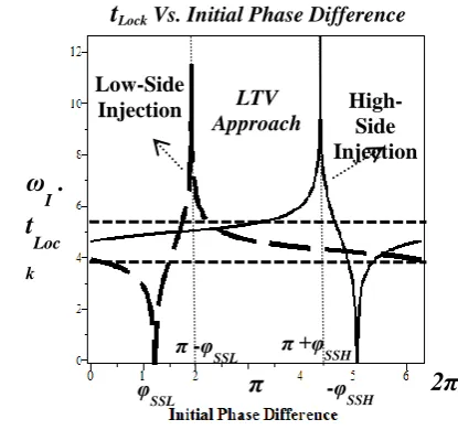
In Fig. 3, the locking time is plotted based on equation (18) which contains both LTI and LTV approaches in the case of low-side injection as well as high-side injection. A similar plot has depicted using simulations in [16] where there is not any closed-form formula for locking time, but using the abovementioned analysis in this work, equation (18) supplies a mathematical relationship to better understanding of the locking process. Locking time
in this figure is normalized by the beat frequency. So, far from roots, using LTI approach, the locking time becomes approximately 4/ωI as mentioned in [16], and [21], otherwise, it reaches zero near stable root, and approaches its maximum value in the vicinity of meta-stable root.
ωinj/ω0
Quality Factor Q
tLock
Fig. 2. tLock versus normalized frequency and quality factor Q
Fig. 3. tLock versus Initial phase difference
4- PHASE NOISE CONSIDERATIONS OF INJECTION LOCKED OSCILLATORS
In recent years, many of the works have addressed the phase noise of the oscillators. Assuming LTI process for an oscillator, some of references have described the oscillator phase noise due to the white noise and studied completely the 1/f 2 region of output spectrum [25]-[27]. Some other works used the time-varying nature of oscillatory systems, and applying Impulse-sensitivity-function approach [28], Phasor-based frequency domain methods [29]-[30], or mixing both of these methods [31] have examined the oscillator phase noise. Making decision to select one of the abovementioned methods leads to a trade-off between accuracy and intuition. Accurate methods based on LTV models need sometimes the primary simulations to extract special characteristics
LTV Approach
ω
I
.
t
Loc
k
Low-Side
Injection High-Side Injection
π
2π
φ
SSL
π -φ
SSL π +φSSH
-φ
SSH
Amirkabir International Journal of Science& Research (Electrical & Electronics Engineering)
(AIJ-EEE)
A. Tofangdarzade, A. Jalali
40 Vol. 46, No. 2, Fall 2014
of a circuit [32], or rely on the numerical methods [33]. So, they could not be a proper choice in this work to study the transient governing the phase noise. Some works have also studied the phase noise in injection-locked oscillators [34]-[35].
The method introduced by Mirzaei in [21]-[22] assumes the phase noise as an injection signal to the oscillator. Since the transient behavior of injection locked oscillator can be described using Adler differential equation, so the transient treatment of phase noise can also be studied this way easily and accurately. Only the white noise induced directly in the Tank circuit of oscillator is analyzed to expand the proposed theory. In Fig. 1, a conventional cross-coupled oscillator equivalent circuit under external frequency injection (Iinj) is shown. Noise current source in in the figure indicates the resultant white noise injected to the output node of oscillator. Assuming the noise source
in as a sinusoidal noise with the angular frequency of ω0
+ ωm, which is injected into the noiseless oscillator, the Adler equation can be rewritten as the following [21]:
0 04
2
n n n ni Sin
d
I
dt
Q
i Cos
(19)Replacing θn– θ = ωmt, and θ → ωosct +
ˆ
, (which
ˆ
can be assumed as the phase noise in this section), then substituting into (19), and knowing that noise current amplitude in comparison with oscillator output current is very small, the following equation is resulted:ˆ 0
2 4 n m
d
i Sin t
dt Q I
(20)Equation (20) simply can be integrated:
0 0 0 0ˆ
2
4
2
4
]
t n m t m n m m mi
t
Cos
t
Q
I
i
Cos
t
Cos
t
Q
I
(21)So, assuming in2/2 = 4KT/R and 4RI/π=Vosc , the phase-noise is resulted as below:
2 0 2 2 0 2ˆ 1 2
2 m osc m KTR Cos t V Q
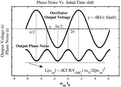
(22)The term (1+2cos2(ωmt0)) multiplied by the phase noise of oscillator is a term that shows the effect of initial phase shift or equivalently time-shift of injected noise due to time-varying nature of oscillatory system. The output voltage and its phase noise are shown in Fig. 4, and it is appeared that in the zero-crossings of output voltage, the phase noise is maximum while in the max or min points, the phase noise has its minimum value which is coincident to the results of the ISF based phase noise study in [28]
-8 -6 -4 -2 0 2 4 6
m t0
O u tp u t V o lt ag e (t ) P h as e N o is e (t )
Phase Noise Vs. Initial Time shift
L[
m] = (KT/RVOSC) (0/2Qm) 2 Oscillator
Output Voltage
/2
3/2 2
Output Phase Noise
y = 4RI/ Sin()
Fig. 4. Phase noise of oscillators as a function of the noise injection time
Now, the phase noise is analyzed again with the existence of another injection signal with amplitude of Iinj and phase of θinj as can be seen in Fig. 1. For this purpose, the noise current in is assumed to be an injection noise signal to the oscillator in the angular frequency of
ω0+ωm, so Adler equation can be rearranged as below to demonstrate the instantaneous phase of the oscillator:
0 0 4 2inj inj n n
inj inj n n
I Sin i Sin
d
I
dt Q I Cos i Cos
(23)Assuming the amplitudes of injection signal and noise current are small in comparison with oscillator current, equation (23) changes to:
0 0
2 4 inj inj n n
d
I Sin i Sin
dt Q I
(24)Applying perturbation analysis using near-locking condition, in addition, assuming θn – θ = ωmt, the following equation is resulted:
0 0
ˆ ˆ
2 4 2 4
inj n
m
I i
d
Cos Sin t
dt Q I Q I
(25)
This differential equation can be rearranged as the following which is similar to the response of first-order circuit to the sinusoidal voltage or current excitation:
0 0
ˆ 1 ˆ
1
,
2 4 2 4
n m
inj n
n
d
a Sin t
dt
I i
Cos a
Q I Q I
(26)
2 2
ˆ ˆ 0 exp
1 1
m n
n
m m
m m
t t
a a
Sin t Cos t
(27)
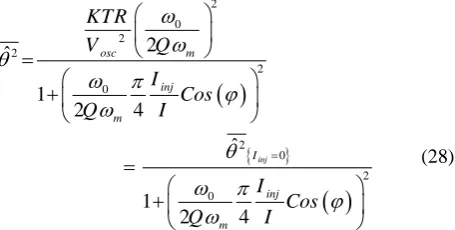
It is evident from (27) that the initial condition of injection does not affect the phase fluctuations after stability of oscillator. In other words, the period that the phase-noise needs to reach steady-state is the same as the period that required for oscillator signal to reach stability. The smaller the time-constant τ, the more agile the system is. Approximately, after a time period 4τ, phase noise approaches to its final value which can be calculated as the following:
20 2 2
2
0
2 0
2
0
2 ˆ
1
2 4
ˆ
1
2 4
inj
osc m
inj
m
I
inj
m
KTR
V Q
I Cos
Q I
I Cos
Q I
(28)
In equation (28), the effects of external injection on phase noise can be found, but, the effect of the time of noise injection could not be shown, because all the initial conditions are exponentially damped and are not effective in the steady-state solution. In next section, this study will be verified using simulations for both LC and Ring oscillators. Letting Iinj=0 results in the same equation for phase noise with [25] model or [21] analysis of stand-alone oscillator phase noise formula. The results also match the phase noise formula extracted in [34] which has assumed the locked oscillator similar to first-order PLL. As it is found from (28), every attempt to shorten the time constant τ, leads to the final phase noise reduction which means increasing injection strength ρ, or injecting as near as possible to the oscillator free-running frequency, decreases the phase noise. However, the quality factor Q plays double role. Hence, with smaller Q, the internal phase noise of oscillator increases, but, considering the denominator of (28), the phase noise reduction also increases. In other words, smaller Q means greater lock range and this phenomenon facilitates the locking of injection signal, and since the injection locking makes the oscillator phase noise superior, therefore, the smaller Q attempts to reduce the phase noise. Consequently, decreasing Q in injection-locked oscillator leads to phase noise increase but not with the similar order that a stand-alone oscillator may suffer from smaller Q. In fact, some of phase noise reduction is compensated through accelerating the injection locking because of greater lock range, and also reduces the phase noise.
5- SIMULATION RESULTS
To examine the transient behavior studied in the previous sections, a scenario for simulation is designed to verify the results of both LTI and LTV findings. First, an LC-cross-coupled oscillator is simulated to demonstrate the accuracy of locking time formula.
A typical 3.65 GHz LC oscillator has been simulated in a CMOS-180n technology Using Hspice. The injected current level is approximately 3.24 dB below the oscillator current level and the lock range of this oscillator is 605 MHz. After 80 ns, the oscillator reaches an initial stable state. Then, a signal is injected into the original oscillator with a frequency of 4.1 GHz with the initial phase shift of 1800, the simulated locking time is about 9.05 ns, while Equation (18) predicts a locking time of 9.40 ns, as shown in Fig. 5.
In order to measure the locking time from the simulations, a method similar to the phase detection in PLLs is used. The phase difference of the injected signal (as the reference) and the output signal is converted to amplitude variations via a phase detector. Now, the rate of change in the resultant amplitude is measured at the instant the injected signal is applied (300 ns), and then it is used to find the time matching the 1% criterion, i.e. the locking time.
Then, to study the locking time dependency to the initial injection phase, we employ two types of LC cross-coupled oscillators shown in Fig. 6, and a conventional four-stage-ring oscillator. Advanced Design System (ADS) tools are used for simulations in the following circuits. To simulate the circuits of the paper using ADS, the technology file of TSMC 180 nm is used. Locking time can be found using time domain simulations tools of the software. It should be noted that, the LC oscillator is designed in one stage, and, Ring oscillator is a four-stage differential oscillator. in the ring oscillator with the even number of stages, the inversion in wiring is necessary to correct functionality of the circuit.
Amirkabir International Journal of Science& Research (Electrical & Electronics Engineering)
(AIJ-EEE)
A. Tofangdarzade, A. Jalali
42 Vol. 46, No. 2, Fall 2014
VDD
inj V
.5 mA 10 nH
10 nH .1 pF .1 pF OUT
Fig. 6. Free-running LC oscillator under injection
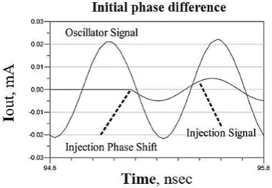
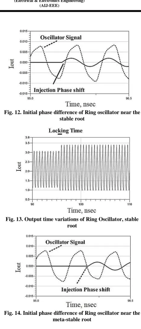
In LC-Oscillator, the free-running frequency is about 1.985 GHz, Q = 7.9, ωL = 157.8 MHz, injection frequency is 50 MHz higher than oscillator frequency. Stable root is tan(φss/2) = -19.480, then meta-stable root is 199.480. In Fig. 7, signal injection with the initial phase difference near the stable root is depicted, while, the resulted output momentary variations is shown in Fig. 8. This case is related to the minimum locking time which is clear in the simulation results. In the other hand, signal injection with the initial phase difference in the vicinity of meta-stable root is depicted in Fig. 9, while, the resulted output momentary variations is shown in Fig. 10. This case is related to the maximum locking time which is clear in the figures as it is mentioned in previous sections. Finally, the time of injection is not important in the amount of phase noise which is shown in Fig. 11, and unchanged for both the initial phase shifts used in the simulation scenario, as well as all possible initial phase differences.
A similar approach is used to examine the time dependent nature of transient response in a 4-stage ring oscillator. The free-running frequency of 1.754 GHz oscillator with the output current of 8 mA becomes injection locked by the current signal with the amplitude of 2 mA with injection frequency of 6 MHz higher than the carrier frequency.
Fig. 7. Initial phase difference of LC oscillator near the smaller root
Fig. 8. Output time variations of LC Oscillator, smaller root
Fig. 9. Initial phase difference of LC oscillator near the meta-stable root
Fig. 10. Output time variations of LC Oscillator, meta-stable root
Fig. 11. Phase noise of LC oscillator under external
injection Offset Frequency, Hz
P.
N
.,
d
B
c/
Hz
Fig. 12. Initial phase difference of Ring oscillator near the stable root
Fig. 13. Output time variations of Ring Oscillator, stable root
Fig. 14. Initial phase difference of Ring oscillator near the meta-stable root
Fig. 15. Output time variations of Ring Oscillator, meta-stable root
The results for locking time in Ring oscillators are similar to the LC counterparts, as seen in Figs. 12-15.
6- CONCLUSION
In this paper, a theoretical study is proposed to describe the transient behavior in both LC and Ring oscillators under the external frequency injection. In fact, a time-domain solution to Adler’s equation is presented for obtaining the locking time taking into account the time-varying nature of oscillators. It is shown that, an oscillator reshapes its output signal after being injection locked based on two roots which are called stable and meta-stable roots. Moreover, the effect of initial phase shift in the locking time is completely formulized. Then, this analysis is expanded to study the transient response and its specifications in Ring oscillators. The results show that, similar to the LC oscillators, there are two roots which shape the transient form of output response, in addition, the initial phase shift is also the most effective factor in oscillator settling time. Next, the phase noise of the oscillator under frequency injection is examined. Then, a mathematical approach is introduced to justify why initial phase shift is not able to change the phase noise of injection locked oscillator. Circuit simulations are employed to verify the expressed locking time equation and proposed transient analysis. The results have good agreement with the theory.
REFERENCES
[1] Adler, R., “A study of locking phenomena in oscillators”, Proc. IEEE, 61, 1380–1385, 1973.
[2] Kurokawa, K., “Injection locking of microwave solid-state oscillators”, Proc. IEEE, 61, 1336-1410, 1973.
[3] Paciorek, L. j., “Injection locking of oscillators”, Proc. IEEE, 53, 1723-1727, 1965.
[4] Razavi, B., “A study of injection locking and pulling in oscillators”, IEEE J. Solid-state circuits, 39, 1415-1424, 2004.
[5] Maffezzoni, P., “Analysis of Oscillator Injection Locking Through Phase-Domain Impulse-Response”, IEEE Trans. Circuits Syst. I, Reg. Papers, 55, 1297-1305, 2008.
[6] Tong, H., Cheng, S., Karsilayn, A. I., and Martinez, J. S., “An injection-Locked Frequency Divider With Multiple Highly Nonlinear Injection Stages and Large Division Ratios”, IEEE Trans. Circuits Syst. II, Exp. Briefs, 54, 313-317, 2007
[7] Rategh, H. R., and Lee, T. H., “Super Harmonic Injection-Locked Frequency Dividers”, IEEE J. Solid-state circuits. 34, 813-821, 1999.
51, 1989-1993, 2003.
Amirkabir International Journal of Science& Research (Electrical & Electronics Engineering)
(AIJ-EEE)
A. Tofangdarzade, A. Jalali
44 Vol. 46, No. 2, Fall 2014
dividers”, IEEE J. Solid-state circuits, 38, 1015-1027, 2003.
[9] Kamogawa, K., Tokumitsu, T., and Aikawa, A., “Injection-locked oscillator chain: A possible solution to millimeter-wave MMIC synthesizers”, IEEE Trans. Microwave Theory Tech., 45, 1578-1584, 1997.
[10] Lyles, U., Copani, T., Bakkaloglu, B., and Kiaei, S., “An Injection- Locked Frequency-Tracking Σ∆ Direct Digital Frequency Synthesizer”, IEEE Trans. Circuits Syst. II, Exp. Briefs, 54, 402-406, 2007.
[11] Chang, H., “Stability Analysis of Self-Injection-Locked oscillators”, IEEE Trans. Microwave Theory Tech.,
[12] Chang, H., “Phase Noise in Self-Injection-Locked Oscillators, Theory and Experiment”, IEEE Trans. Microwave Theory Tech., 51, 1994-1999, 2003.
[13] Chang, H., Cao, X., Mishra, U., and York, R., “Phase noise in coupled oscillators: Theory and experiment”, IEEE Trans. Microwave Theory Tech., vol. 45, pp.604 -615, 1997.
[14] Chang, H., Cao, X., Vaughan, M., Mishra, U., and York, R., “Phase noise in externally injection-locked oscillator arrays”, IEEE Trans. Microwave Theory Tech., vol. 45, pp.2035 -2042, 1997.
[15] Maffezzoni, P., D'Amore, D., “Phase-Noise Reduction in Oscillators via Small-Signal Injection”, IEEE Transactions on Circuits and Systems I: Regular Papers, Volume: 58, Issue: 10, 2498 - 2507, Oct. 2011.
[16] Harjani, R., Lanka, N., and Patnaik, S., “Fast hopping injection locked frequency generation for UWB”, Proc. IEEE Int. Conf. Ultra-WideBand, pp.502 -507, 2007.
[17] Lanka, N., Patnaik, S., and Harjani, R., “Sub-10 ns frequency hopping synthesizer based on injection-locking”, Proc. 38th European Microwave Conf., pp.1581 -1584, 2008.
[18] Lanka, N., Patnaik, S., and Harjani, R., “Frequency-hopped quadrature frequency synthesizer in 0.13 μm technology”, IEEE J. SolidState Circuits, vol. 46, no. 5, pp.2021 -2032, 2011.
[19] Lanka, N., Patnaik, S., and Harjani, R., “Understanding the transient behavior of injection locked LC oscillators”, Proc. IEEE 2007 Custom Integrated Circuits Conf. (CICC), pp.TP-291 -TP-294, 2007.
[20] Mirzaei, A., Heidari, M., and Abidi, A., “Analysis of oscillators locked by large injection
signals: Generalized Adler's equation and geometrical interpretation”, Proc. IEEE Custom Integrated Circuits Conf. (CICC), pp.737 -740, 2006.
[21] Mirzaei, A., Heidari, M., Bagheri, R., Chehrazi, S., and Abidi, A., “The quadrature LC oscillator: A complete portrait based on injection locking”, IEEE Journal of Solid-State Circuits, vol. 42, pp. 1916-1932, 2007.
[22] Mirzaei, A., Heidari, M., Bagheri, R., Chehrazi, S., and Abidi, A., “Multi-phase injection widens lock range of ring-oscillator-based frequency dividers”, IEEE J. Solid-State Circuits, vol. 43, no. 3, pp.656 -671, 2008.
[23] Saniei, N., Tofangdarzade, A., and Ng, W. T., “Locking Time of Oscillators under External Frequency Injection”, in Proc. IEEE ICEE, 18th Irainian Conference on Electrical Engineering, pp. 391-396, 2010.
[24] Gangasani, G., and Kinget, P., “A time-domain model for predicting the injection locking bandwidth of non-harmonic oscillators”, IEEE Trans. Circuits Syst. II, Exp. Briefs, 53, 1035-1038, 2006.
[25] Leeson, D., “A simple model of feedback oscillator noise spectrum”, Proc. IEEE, vol. 54, no. 2, pp.329 -330, 1966.
[26] Razavi, B., “A study of phase noise in CMOS oscillators”, IEEE J. Solid-State Circuits, vol. 31, no. 3, pp.331-343,1996.
[27] Everard, J., Xu, M., Bale, S., “A Simplified phase noise model for negative-resistance oscillators and a comparison with feedback oscillator models”, IEEE Trans. On Ultrusonics, Ferroelectrics and frequency control. Vo. 59, No. 3, pp. 382-390, 2012.
[28] Hajimiri, A., and Lee, T., “A general theory of phase noise in electrical oscillators”, IEEE J. Solid-State Circuits, vol. 33, no. 2, pp.179 -194, 1998.
[29] Samori, C., Lacaita, A., Villa, F., and Zappa, F., “Spectrum folding and phase noise in LC tuned oscillators”, IEEE Trans. Circuits Syst. II, Analog Digit. Signal Process., vol. 45, no. 7, pp.781 -790, 1998.
[30] Rael, J. and Abidi, A., “Physical processes of phase noise in differential LC oscillators”, Proc. IEEE Custom Integr. Circuits Conf., pp.569 -572, 2000.
Papers, Volume.57, No. 6, pp. 1187-1203, 2012.
[32] Lee, T., and Hajimiri, A., “Oscillator phase noise: A tutorial”, IEEE J. Solid-State Circuits, vol. 35, no. 3, pp.326 -336, 2000.
[33] Demir, A., Mehrotra, A., Roychowdhury, J., “Phase Noise in oscillators: A unifying theory and numerical methods for characterization”, IEEE Transactions on Circuits and Systems I Fundam. Theory Appl., Volume.47, No. 5, pp. 655-647, 2000
[34] Kalia, S., Elbadry, M., Sadhu, B., Patnaik, S., Qiu, J., Harjani, R., “A simple, unified phase noise model for injection-locked oscillators”, Radio Frequency Integrated Circuits Symposium (RFIC), IEEE, 1 – 4, 2011.