Progressive Collapse Analysis of a Regular Structure
Ashna T E
1, Nivya John
21M.Tech student, Department of Civil Engineering, Indira Gandhi Institute of Engineering and Technology for
women, Kerala,India
2Assistant Professor,Department of Civil Engineering, Indira Gandhi Institute of Engineering and Technology
for women, Kerala,India
I.INTRODUCTION
Progressive collapse is one of the most important types of building failures, most often leading to costly damages, multiple injuries, and possible loss of life. Factors such as construction errors, miscommunication, poor inspections, or design faults contribute to these progressive collapses, which have leads to many changes in building codes throughout the world. In US, the General Services Administration (GSA) provide a comprehensive guidelines and procedures for progressive collapse. The GSA criterion contains the threat independent approach for the progressive collapse. Progressive collapse analysis is important for building structures to provide aeconomic and safe design against progressive collapse. The General Services Administration (GSA) of the United States defines this phenomenon as „a situation where local failure of a primary structural component leads to the collapse of adjoining members which, in turn, leads to additional collapse. Hence, the total damage is disproportionate to the original cause‟.Progressive collapse, as defined by ASCE Standard 7-05 is―the spread of an initial local failure from element to element resulting, eventually, in the collapse of an entire structure or a disproportionately large part of it‖ (ASCE 2005). The disproportionality refers to the situation in which failure of one member causes a failure, with a magnitude disproportionate to the initial event.It is a dynamic process, usually accompanied by large deformations, in which the residual structure continually seeks alternative load paths in order to survive. One of the important characteristics of progressive collapse is that the final damage is not proportional to the initial damage.
Progressive collapse of a structure takes place when the structure has changed its loading pattern or boundary conditions changed such that structural elements are loaded beyond their ultimate capacities and fail. Once a column is damaged due to accidental loads like fire, impact loading and blast loading, the building‟s weight (gravity load) transfers to the neighboring columns in the structure. It is a process in which elements of the structural system which is taken the desired gravity load distributes the gravity load to prevent the loss of critical element like column.
II.GSA LIMIT FOR ACCEPTANCE
The GSA describes the use of the DCR (Demand- Capacity Ratio), the ratio of the member force and the member strength, as a reference to define the failure of main or important structural members by the linear analysis method.
DCR = Q UD/ Q CE Where, Q UD
= demand determined in component (moment, axial force, shear, and possible combined forces)
Abstract—
Progressive collapse of buildingsare generally triggered by a local failure due to accidental actions, followed by subsequent chain effect of the structures which may result in wide range failure or even collapse of the entire buildings. To study the effect of failure of load carrying elements i.e. columns on the entire structure; 10 storey moment resistant regular RC building is considered. The buildings are modelled and analyzed for progressive collapse using the structural analysis and design software SAP2000. The frame is subjected to loading as described by General Services Administration (GSA) guideline for carrying out linear static analysis.Linear static and nonlinear static analysis is used to evaluate the potential for progressive collapse of RC buildings.The results include the variation of bending moment of beams and evaluation of demand capacity ratios (DCR), hinge properties and % load attempt.Q
CE = Expected ultimate, un-factored capacity of the component (moment, axial force, shear and possible combined forces)
The allowable limit of DCR values for primary and secondary structural elements are:
DCR< 2.0 (Typical structural configurations)
DCR< 1.5 (A-typical structural configurations)
For static analysis purposes the following vertical load shall be applied downward to the structure under investigation:
Load = 2(DL + 0.25LL)
III.BUILDING CONFIGURATION
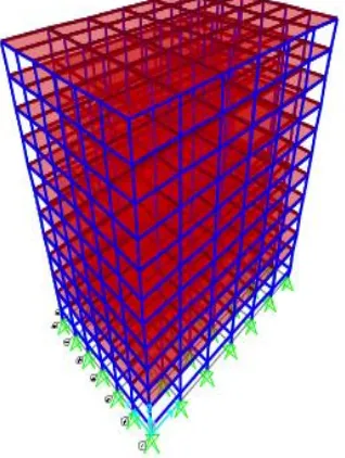
A 10 storey reinforced concrete residential building of an importance factor 1 (IS code 1893-2002) was selected for performing progressive collapse analysis as per GSA guidelines. Bay size is taken as 6m in one direction and 4m in other direction. Building size in plan is 36m x 24m. Height of base to plinth is taken as 1.5m, Plinth to ground floor as 3.5 m, which is considered as hollow plinth and height of typical floor as 3m. The walls having 230mm thickness are assumed on all thebeams.Beam size: 300mm × 600mm,Column size: 550mm × 550mm and Slab thickness: 150mm which is considered as a shell element are considered for the building. Reinforced concrete design is carried out and percentage steel is provided accordingly. Steel design for this building is governed by the earthquake load combination envelope. Figure below shows typical floor planand 3D view ofregular building.
Figure 1: Typical floor plan of regular building and column removal scenarios
IV.PROGRESSIVE COLLAPSE ANALYSIS
Progressive collapse analysis is performed by instantly removing one or several columns and analyzing the building‟s remaining capability to absorb the damage. The key issue in progressive collapse is in understanding that it is a dynamic event, and that the motion is initiated by a release of internal energy due to the instantaneous loss of a structural member. This member loss disturbs the initial load equilibrium of external loads and internal forces, and the structure then vibrates until a new equilibrium position is found or until the structure collapses. Load case defined for linear static analysis and nonlinear static analysis are same, which is 2 (DL + 0.25 LL), Where DL= Dead Load and LL = Live Load. Four column removal cases for progressive collapse analysis are considered as shown in Figure1.
A. Linear Static Analysis
GSA guideline has provided following stepwise procedure to carry out linear static analysis.
Step 1: Prepare three dimensional model of structure and perform concrete design and determine the reinforcement to be provided in members.
Step 2: Based on the reinforcement provided, calculate the capacity of the member in flexure, “strength increase factor” is considered during progressive collapse.
Step 3: Column loss scenario are created by removing ground floor column from the specified location one at a time as mentioned in GSA guidelines.
Step 4: static linear analysis is performed and the demand for the specific column removal case are determined.
Step 5: Calculate the “demand to capacity ratio (DCR)” and evaluate the results as per the acceptance criteria
provided in GSA guidelines.
The performance of structure is evaluated by demand to capacity ratios (DCR), which should not exceed 2 for regular structures and 1.5 for irregular structures or else they are considered as severely damaged or failed. GSA has defined DCR as below.
DCR = Demand / Capacity
B. Non-Linear Static Analysis
GSA guideline has provided following stepwise procedure to carry out Non-linear static analysis.
Step 1: Prepare three dimensional model of structure and perform concrete design and determine the reinforcement to be provided in members.
Step 2: Define and assign plastic hinges to beams and columns.
Step 3: Define the load combination as per GSA and define non-linear case.
Step 4: Remove the column and perform the static non-linear analysis.
Step 5: Observe the hinge formation pattern for failure.
Load case defined for static nonlinear analysis is same as static linear analysis, which is 2 (DL + 0.25 LL), Where DL= Dead Load and LL = Live Load.
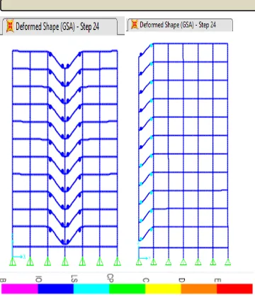
Figure 4: Hinge formation for Non-linear static analysis
V. CALCULATION OF DCR (DEMAND CAPACITYRATIO)
Column damage scenario is created by removing the external Long bay CR 1 and Linear Static Analysis is performed. After performing the progressive collapse analysis, flexure demand of the beams are found. Figure shows the bending moment and shear force diagram of before column removal condition and after column removal condition for static linear analysis. These analyses should be carried out for all four column removal cases.
DCR for Flexure = Demand Moments / Flexure Capacity of Member
The bending moment diagrams and value of DCRalong the height in horizontal andtransverse direction frame is shown in following figures.
Figure5: Bending moment diagram for column removal in long bay.
PERCENTAGE GSA LOAD ATTEMPT
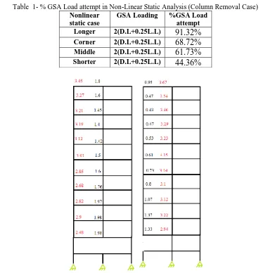
Table 1- % GSA Load attempt in Non-Linear Static Analysis (Column Removal Case)
Nonlinear static case
GSA Loading %GSA Load attempt Longer 2(D.L+0.25L.L)
91.32%
Corner 2(D.L+0.25L.L)68.72%
Middle 2(D.L+0.25L.L)61.73%
Shorter 2(D.L+0.25L.L)44.36%
Figure 6: DCR values of beamsfor column removal case in long bay and short bay.
VI. RESULTS AND DISCUSSION
In this studylinear static and non-linear static analysis procedures are carried out for progressive collapse analysis of 10-storey moment resistant RC building. DCR are found out for beams and they are highly stressed nearby columns at all storeys for four column removal cases. It is observed that DCR in flexure in beam exceeds permissible limit of 2 in all column removal cases of building but the severity varies from each column removal cases.DCR calculated in flexure for beams by linear static analysis is higher on left and right side of column removal points.
Nonlinear static analysis is carried out to understand the hinge formations at yield and at collapse.Nonlinear static analysis gives maximum collapse load for all the column removal cases. In Nonlinear analysis structure is considered to have enough resistance against progressive collapse if the percentage load carried by the structure after loss of column exceeds 50%.
REFERENCES
[1]. General Services Administration (GSA), (2003), Progressive collapse analysis and design guidelines for new federal office buildings and major modernization projects, GSA.
[2]. SAP 2000 Advanced structural analysis program, Version 15. Computers and Structures, Inc. (CSI). Berkeley, CA, U.S.A.
[3]. ShalvaMarjanishvili and Elizabeth Agnew, “Comparison of Various Procedures for Progressive Collapse Analysis”, Journal of Performance of Constructed Facilities, ASCE, Vol. 20 : 365-374, November 2006. [4]. UweStarossek, “Typology of Progressive Collapse, Engineering Structures”, Elsevier Journal, Vol. 29:
2302-2307, 2007.
[5]. D.A Nethercot, “ Design of building structures to improve their resistance to progressive collapse”, Procedia Engineering14(2011)1-13.
[6]. Hongyu Wang, Youp Su, QingshenZeng, “Design methods of RC framed structures to resist progressive collapse in Civil Engineering”, Systems Engineering Procedia 1 (201 1) 48–54.