An Efficient Dual Edge Triggered Sense Amplifier
Flip-Flop (DETSAFF) with Current Steering
Logic Application
Savita Pandey1 and Padmini Sahu2
1M. Tech Student Department of Electronics and Communication,
Dr. C. V. Raman University, Kota, Bilaspur, INDIA.
email: [email protected]
2Assistant Professor,Department of Electronics and Communication, Dr. C. V. Raman University, Kota, Bilaspur, INDIA.
(Received on: June 2, 2016)
ABSTRACT
This paper presents a new improved Power Efficient Dual Edge Triggered Sense Amplifier Flip-Flop (DET-SAFF) with Current steering logic incorporated in it make it more Power and delay efficient. Power dissipation in power efficient flip flop is very less as compare to normal flip flops. The Dual Edge Triggered flip-flops responses to both positive and negative edge of clock, hence this flip-flop can significantly reduce the clock related power as well as delay and hence is a power and delay efficient flip-flop. To reduce this delay and power dissipation further Current Steering (CS) mechanism is incorporated with DET-SAFF. Proposed logic is developed in CMOS .18μm Technology and simulated with Virtuso in Cadence design environment. Experimental results shows delay and power reduction of 21% and 99% of those of previous DET-SAFF.
Keywords: Current Steering Logic, Dual Edge Triggering, Conditional Precharging.
I. INTRODUCTION
of today’s digital system reduction in power dissipate, to is must, specifically in clock distribution networks and flip-flops. At the same time due to tight timing budget at high frequency operation, the latency of the flip-flops should be minimized.
In dual-edge triggering, the flip-flop is capable of sampling data on both rising and falling edges of the clock so that only half the clock frequency is needed to obtain the same data throughput of single edge-triggered flip-flops (SETFFs)2. Hence dual-edge triggering can
significantly reduce the power consumption in the clock distribution network. DET-SAFF also minimizes the latency by making use of a fast symmetrical latch3.
To improve the performance further we have modified the DET-SAFF by adding Current-Steering logic into it. A pair of complimentary transistors is added in parallel to DET-SAFF in order to get constant current operation. Pair of complimentary transistors provides additional paths for the d-c bias current to flow, hence DET-SAFF do not draw any appreciable current in its static state, facilitating constant-current operation. A P-channel transistor sources a constant-current to DET-SAFF.
Rest of the paper is organized in the following manner. In Section II, the recently published power efficient dual-edge triggered sense amplifier flip-flops (DET-SAFFs) is reviewed.
Section III presents the structure and operating principle of the proposed CS-DETSAFF. In Section IV, CS-DET-SAFF is compared with already designed DET-SAFF. Finally, we draw our conclusion in Section V. At last Section VI contains References.
II. REVIEW OF POWER EFFICIENT DET-SAFF
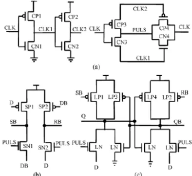
Fig. 1 represents the schematic diagram of the power efficient DET-SAFF3. It consists
of three stages: the pulse generating stage, the sensing stage and the latching stage. The dual edge triggered pulse generator produces a brief pulse signal (PULS) synchronized at the rising and falling clock edges.
In the sensing stage as soon as D is low, SB will be set to high, and if D is high, RB will be set to high. Therefore, the conditional precharging technique is applied in the sensing stage of DET-SAFF, to avoid redundant transitions at major internal nodes. Conditional precharging is based on creating two narrow transparency windows during which the logic level of the input D can be transferred to the output4. Two input controlled pMOS transistors,
SP1 and SP2, are embedded in the precharge paths of nodes SB and RB, respectively. In this case, if D remains high for n cycles, SB may only be discharged in the first cycle. For the following (n-1) cycles, SB will be floating when PULS is low or fed to the low state DB when PULS is high. As for RB, it only needs to be precharged in the first cycle and remains at its high state for the remaining cycles. Since the precharging activity is conditionally controlled, the critical pull down path of SB and RB is simplified, consisting of only one signal transistor. This helps to reduce the discharging time significantly. As such, the resulting sensing stage possesses low-power and high-speed features. To further improve the operating speed, a fast symmetric latch is developed, which makes use of SB and RB to pull up the output nodes. But the pull down path is modified. It composes a PULS-controlled nMOS pass transistor, through which D (DB) is directly fed to the Q (QB) node. This topology significantly speeds up the high-to-low output transition because the output latch immediately captures the input value once the PULS signal is generated. On the other hand, the low-to-high latency will also be improved. This is because the output node will not only be charged by the pull-up transistors, LP1 and LP2, but also the pass transistors, LN1 and LN2. Note that the pass transistors cannot fully charge a node to high, but it can assist with the pull-up transition. The four inner transistors, LP3, LP4, LN3, and LN4, are of minimum sizes, serving the purpose of maintaining the output state when the flip-flop is opaque. For the proposed DETSAFF and previously mentioned dual edge designs, such as the SCDFF and DSPFF, the power saving techniques are only applicable for the latch part of the flip-flops. As the switching activity of the clock signal is 1, the pulse generator will always be operating even when the input invokes no output changes. These unnecessary transitions cause a lot of power to be wasted, especially at low input switching activities.
III. IMPLEMENTATION OF PROPOSED CURRENT STEERING DET-SAFF
Proposed Current-Steering DET-SAFF is shown in Fig. 2. The CS-DETSAFF is obtained by a simple current-steering modification to the standard DET-SAFF. Here Drain terminal of M1 is connected to the supply input of DET-SAFF to sources a constant-current to DET-SAFF. M2 and M3 forms the complementary transistor pair to provides additional paths for the d-c bias current to flow, hence DET-SAFF do not draw any appreciable current in its static state, facilitating constant-current operation.
Fig. 2 Proposed Current Steering DET-SAFF
IV. PERFORMANCE ANALYSIS
For this analysis, single poly, 0.18 micron CMOS technology is used. Transistor sizes are selected to be compatible of the technology. For this comparative study, transistors sizes in both flip-flops were kept of the comparable dimensions. Both configurations are circuit simulated with Virtuso in Cadence design environment. Data and clock rise/fall times of 1ns are used. In addition, the DET-SAFF and CS-DET-SAFF are simulated at room temperature, 1.8V input supply voltage and no load conditions.
4.1 Comparison in terms of Propagation delay
Propagation delay is calculated as average of data rise and fall time as given below:
tPd = (tPHL + tPLH) / 2
Where tPHL is the time required in high to low transition and tPLH is the time required in low to
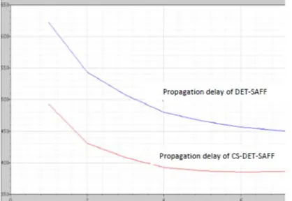
high transition. In Fig. 3 propagation delay is plotted as a function of different value of source current I. To vary the source current W/L ratio of M1 is varied. In Table 1 propagation delay of DET-SAFF and proposed CS-DET-SAFF are compared with varying source current value.
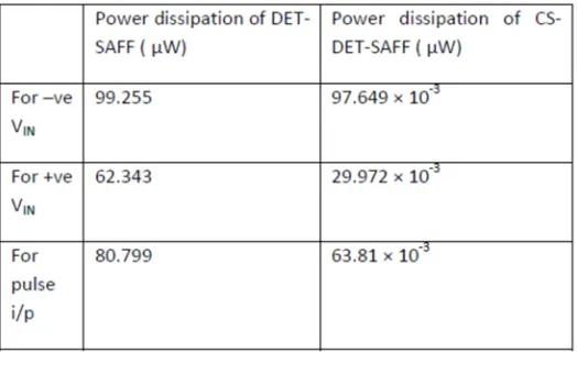
This can be clearly observed that by using Current Steering logic propagation delay of DET-SAFF can be reduced significantly upto 21%. In Table 2 Power Dissipation of both flip-flop are listed for positive and negative transition of input signal. We can conclude that after combining Current-Steering logic with conventional DET-SAFF, power dissipation reduces to a great extent.
Table 1: Comparison of Propagation delay for different value of Steering current
4.2 Comparison in terms of Power Dissipation
Power dissipation from the range of μW reduces upto nW, hence we can say a reduction of 99% can be achieved in power Dissipation by using Current-Steering logic.
V. CONCLUSION
In this paper already designed DET-SAFF is modified by adding Current-Steering logic. We have done the comparison of both flip-flop in terms of propagation delay and power dissipation. As per the analysis done in this paper CS-DET-SAFF is found to have the better performance then DET-SAFF. While increasing the source current IS continuously, percentage reduction in tPD does not keep track of. Hence the design can be optimized for W/L ratio of M1 as 2. This is the preliminary analysis and it can be extend further for different parameters. But the reduction in power dissipation is 99% which is of great amount and can be utilized to reduce the power dissipation drastically. Simultaneously propagation delay is also reducing by 21%.
VI. REFERENCES
1. R.P. Llopis and M. Sachdev, “Low Power, Testable Dual Edge Triggered Flip- Flops”,
International Symposium on Low Power Electronics and Design, pp.341-5 (1996).
2. Borivoje Nikolic, Vladimir Stojanovic´,Wenyan Jia James Kar-Shing Chiu, and Michael
Ming-Tak Leung “Improved Sense-Amplifier-Based Flip-Flop Design and Measure-ments”, IEEEJournal of Solid-State Circuits, Vol.35, pp. 877 NO. 6, JUNE (2000).
3. Myint Wai Phyu, Kangkang Fu, Wang Ling Goh, and Kiat-Seng Yeo, “Power- Efficient Explicit-Pulsed Dual-Edge Triggered Sense-Amplifier Flip-Flops”, IEEE Transactions on
Very Large Scale Integration (VLSI) Systems, Vol. 19, NO. 1, pp 1-4 January (2011).