R E S E A R C H A R T I C L E
Open Access
Some remarks on surface conditions of solid
body plunging into water with particle method
Masao Yokoyama
1*, Yoshihiro Kubota
2, Kenji Kikuchi
3, Genki Yagawa
4and Osamu Mochizuki
3* Correspondence:masao. [email protected] 1School of Information Science,
Meisei University, 2-1-1 Hodokubo, Hino, Tokyo 191-8506, Japan Full list of author information is available at the end of the article
Abstract
Background:The water splash patterns strongly depend on the surface conditions of the solid object. The present paper discusses the influence of the surface conditions of the solids falling into the water on the formation of the splashes, employing the experimental method with the high speed video camera and the numerical approach by the particle method.
Methods:We propose two engineering models for calculating the Navier–Stokes flows to distinguish the different surface conditions of the solids falling into the water. One is to add the attractive or repulsive force between the water and the surfaces of the solids, and the other is to consider the swelling ratio as the slip condition, which causes the different wall shear stresses at the interfaces between the solids and the water.
Results:The above models are successfully employed to study the effects of the differences of the surface conditions of the falling objects on the splash formations.
Conclusions:We have successfully calculated the splashes caused by the different surface conditions of spheres using the MPS method.
Keywords:Splash; Surface condition; Slip; Swelling ratio; Particle method; MPS method
Background
Fluid Structure Interaction (FSI) is one of the most important themes in the computa-tional mechanics and many related studies have been performed in the wide fields such as structures, vehicles, medicine and biomechanics (Idelsohn et al. [1], Saksono and Perić[2], Angeles et al. [3]).
In the fields of biology and biomechanics, the studies of an aneurysm model by the groups of Takizawa et al. [4], an aneurysm or arteriosclerosis by Borghi et al. [5] and Khanafer et al. [6] and an interfere between blood and deformed vessel by Tallec et al. [7], Gerbeau et al. [8] and Yokoyama and Mochizuki [9] have been performed among others. Regarding the relation with the bionics, there are some interesting researches of flow dynamics caused by creature [10-12].
Creatures living in water such as frog or fish have a slimy mucus skin, where the principal ingredient of the mucus is a hydrogel known as mucin [13]. Kikuchi et al. [14] investigated the flow near the hydrogel surface as a hydrophilic material, where they studied the slippery flow on the hydrogel surface and determined the relation
between the strength of the hydrophilicity of hydrogel and the slip velocity on the hydrogel surface. One of the topics on the Fluid Structure Interaction related above is the mechanics of splash caused by creatures living in water. Manservisi et al. [15] studies the interaction between a droplet and the surface of a wall and numerically simulated the spreading of a single droplet impacting over horizontal dry surfaces. Some focused on the contact angle of a droplet on a solid surface [16,17], studying the surface tension related with the multiphase flow [18,19]. Rebouillat et al. [20] and Idelsohn et al. [21] calculated the sloshing of a liquid filled partially in a container as problems of solid and fluid inter-action. They used the Finite Element Method (FEM) to solve the flow with free surface with large deformation and many droplets. Alam et al. [22] indicated that the surface tension of a splash becomes prominent with small-scale phenomena.
The milk crown formed by a droplet falling into milk was studied by several researchers [23,24]. The splash by splining sphere was studied by Truscott and Techet [25]. Kubota et al. [26] experimentally observed different splash patterns due to the different impact speed of a solid sphere impinging on the surface of water. Bussmann et al. [27] studied the formation of the finger at the edge of water film. Akers et al. [28] studied the influence of the non-Newtonian fluid on the splash formation, focusing on the property of water. Duez et al. [29] reported the relation between the splash formation and the sound generation, studying the effect of the hydrophobic or hydrophilic surface of the body on the mechanism of the splash. Some studies were reported on the splash and the droplet dealing with the free surface flow employing the particle methods [30-33].
However, most of the above researches, assuming the non-slip condition at the solid–fluid interface, have ignored the effects of the surface properties of the solid on the results.
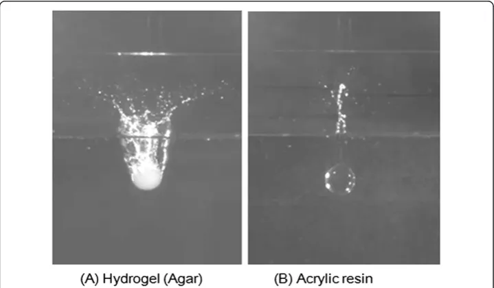
The need to consider the surface properties in the splash formation can be seen in the experimental results as shown in Figure 1, where Figure 1(A) shows the crown-type splash generated by a hydrophilic object (hydrogel) and Figure 1(B), on the other hand, the column-type splash generated by an object of the weaker hydrophilicity (acrylic resin). The comparison of these figures shows that the splash patterns strongly depend on the
surface conditions of the solid object. It is noted that the fact that the forms of splash caused by a solid sphere with the same weight and the same diameter differ according to the surface condition is not known in general.
In the present paper, a model for calculating the flow on the special boundary condi-tion such a slip on biological surface or an electrical attractive/repulsive force of resin is proposed and applied it to the splash simulation.
Methods
Experimental observation
An experiment on the splash generated by a diving sphere with different surface condi-tions is performed to observe the influence of different surface condicondi-tions on the splash formation, where we use the diving sphere made of agar as the hydrophilic material. The agar is a kind of hydrogel like gelatin, and known to be easy to control its water content and to create arbitrary shape. For example, Eddington et al. [34] reported the use of the hydrogel as the valve for flow control of a microchannel, and Beebe et al. [35] discussed the effectiveness of hydrogel structure for flow control on micro fluidic channels.
The test condition is as follows: the radius of a sphere Ris 10 mm, the initial height
h is 50R, and the impact velocity of the sphere at the water surfaceViis 2.4 m/s. The impact velocity is determined according to the conservation of energy, because the air drag is negligible for the range of heights in this study. The dynamic views of the splash are recorded by using a high speed CMOS camera (Vision Research Inc., Phantom v7.1), where the camera is set as 4000 frames per second so that precision timing between consecutive images is 0.25 ms.
The experimental results of a splash formed by a sphere impinging on water surface are shown in Figure 1, comparing the primary splash formed by a hydrogel sphere (Figure 1(A)) with that by an acrylic sphere (Figure 1(B)). The primary splash means the splash, which rises first after an object plunging. The primary splash formed in the case of the hydrogel is a kind of the crown-type. On the other hand, the acrylic sphere makes the column type primary splash. The splashes are considered to be formed by the dynamics of the film-flow [26], which is a thin water flow around a sphere surface and generated immediately after the sphere impacts the water surface. The difference between the formation processes of Figures 1(A) and (B) is due to the difference of the film separation from the sphere surface.
When the film is separated from the sphere surface, a crown-type splash is formed. The above film separation is presumably caused by the increase in the film velocity accord-ing to the hydrophilic property of the solid wall and the attractive or repulsive force such as the electrostatic force between the solid wall and the water. This experimental observation suggests that the numerical simulation should take into consideration the various surface conditions as the interaction between the object and the water.
Governing equations and MPS method
The governing equation of the present flow is the incompressible Navier–Stokes equation as follows,
Du→ Dt ¼F−
1
ρ∇Pþν∇2u
→ ð
whereuis the velocity vector of fluid,ρis the density of fluid,Pis the pressure,νis the kinematic viscosity of fluid andFis the external force including the gravity.
Employed in the present paper is the Moving Particle Semi-implicit (MPS) method, which is one of the particle methods. Assuming two particles iandj, where there exist, respectively, pressurepiandpj. The gradient of pressure at the pointiis written as [30]
∇P¼ d n0
X
j≠i
pj−pi
r →
j−r
→
i
2 r
→
j−r
→
i
κ →rj−→ri
2 6 4 3 7
5 ð2Þ
wheredis the constant value, which is equal to the dimension of space to be analyzed andn0is called the particle number density. The Laplacian of velocity at xthe pointiis written as [30]
∇2u→¼ 2d
λn0
X
i≠j
u →
j−u
→
i
κ →rj−→ri
h i
ð3Þ
where λ is a parameter, which is introduced in order to make statistical distribution coincided with an analytic solution [28], andκis the weight function assumed as follows,
κð Þ ¼r re
r−1 ð0≤r≤reÞ 0 ðre≤rÞ
(
ð4Þ
Here,ris the distance between two particles andreis the cut-off radius. The algorism of MPS method takes the following steps:
i) The tentative velocityu−is calculated at the explicit stage with the Navier–Stokes equation (1),
ii) The Poison’s equation is solved at the implicit calculation stage to solve the pressurep. Then, the velocityu* is modified withpsolved above in order that the particle number density within a domain is conserved. Finally,u* is added tou−to obtain the target velocityuatt.
iii) The time step is updated ast=t+dt, wheredtis set 0.001 sec in the present paper.
Swelling ratio and slip ratio on hydro-gel surface
We discuss here how we introduce the influence of slip in the horizontal direction on the hydro-gel wall into the calculation, which is a heuristic approach.
Figure 2 shows the velocity distributions of water flow near the surface of the acrylic resin versus that of the agar, whereδis the height of water flow anduis the velocity of water [14]. Here,τ being the wall shear stress under the no-slip condition andτ’that under the slip condition, the slip ratioαis defined as follows,
α¼τ′=τ ð5Þ
Figure 3 shows the experimental relations between the swelling ratio S and the slip ratio αfor the agar-gel and the carrageenan-gel, respectively, where the swelling ratioS
is defined as follows [36],
S¼ mwaterþmgel
where mwater is the mass of water andmgel that of the solid-gel. S increases with the
amount of water contained in the solid-gel. The agar employed in this study is a kind of hydrogel, which is easy in handling and controlling its shape and the degree of the swelling. Figure3suggests thatαdecreases with the increase ofS, or can be expressed as
α¼1−βS ð7Þ
whereβis estimated to be 1.2 × 10⁻³in the case of the agar. It is summarized that largerS gives more slip on the surface.
In this paper, the above relation between the increase of the swelling ratio and the reduction of the wall friction from our experiment is taken into consideration near the wall in the viscous term of the Navier–Stokes equation in a heuristic manner. Since the shear force acting between the wall and the fluid is directly related with the viscosity term of Eq. (3), we modify the term as
∇2u→¼ 2d
λn0
X
i≠j
u →
j−u
→
i
κH →rj−r
→
i
h i
ð8Þ Figure 2Schematic views (Left) and experimental results (Right) of flow profiles near no-slip wall (acrylic resin) and slippery wall (hydrogel) [14].
with
κHð Þ ¼r ακð Þr ð9Þ
where index idenotes the water particle near hydro-gel wall andj the surface particle of hydro-gel wall. Namely, α is set effective only near the hydrogel wall, because the effect of slip is available near this area. The effective length of the above reduced weight function near the wall is assumed to berein this study, and set to be 2.1l0, wherel0is the
initial distance between the particles.
Summarizing the above procedure, i) selectSaccording to the hydrophilicity of the solid object, ii) estimateαusing Eq. (7), and iii) applyαto the weight function of viscous term of Navier–Stokes equation for the calculation of shear force near the hydrogel wall using by Eqs. (8) and (9).
Attractive and repulsive forces due to electrostatic effect
In order to simulate the column-type splash, which occurs in the case of acrylic resin sphere, a model of the external force F is discussed here, which is the attractive or repulsive electrostatic force on the interface between water and the wall. Here, we propose a heuristic model of the force acting between water molecules.
The attractive or repulsive force between water and the wall is modeled as an electro-static force [37] in an intuitive and engineering manner. Namely,Fin Eq. (1) is assumed to consist of the gravitygand the electrostatic forceTEas
F¼gþTE ð10Þ
whereTEis the attractive or repulsive force between the particlesiandj, which is defined as
TE;ij¼CE;ij
dϕijð Þr
dr ð11Þ
with
CE;ij¼ ≠
0 ði¼water particle and j¼particle at the wallÞ;or vice versa:Þ
¼0 ðotherwiseÞ
ð12Þ and
ϕijð Þ ¼r
1 4πε0
qiqj
rij ð
13Þ
whereqiandqjare the electric charges andrijis the distance between the particleiandj. In the present study, we assume the case of water, namely, the electric charge qiand
qj= 1.6 × 10⁻¹⁹ [C] [38], and the vacuous dielectric constant ε0= 8.854 × 10⁻¹² [F/m]. The effective range from the wall ofTEis assumed to be equal to bere, which is 2.1l0.
Results and discussion Condition for simulation
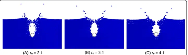
uniformly arranged in the lattice pattern and the initial distance between particlesl0is set 4 × 10⁻³m after some test. The cut-off radiusreis set to be 3.1 [30]. Because these values,
l0andre, give influence on the result, we compare the dependency ofl0andreto confirm the consistency and the convergence on the solutions in what follows.
Figure 4 shows the comparison of the crown-type splash patterns with different values ofre. The patterns of splash are almost the same betweenre= 3.1 and 4.1, then we set re= 3.1 in this paper. Figure 5, on the other hand, shows the snapshots of the crown-type splash with different values ofl0. Since the simulation results withl0= 2 × 10⁻³m and
l0= 4 × 10⁻³m are similar and compared well with the experimental result, we have decided to employl0= 4 × 10⁻³m in the present simulation.
Both the width and the depth of the water tank are 20R, which are set to be sufficiently large so that the effects of the size of these are negligible. The boundary condition of the tank’s wall is no-slip condition with 3 lattices of solid particles. The regular time step of this calculation is set to be 1 m sec, but it is controlled automatically according to the Courant conditions.
The simulated pattern of the collapse of the water column is compared with the ex-perimental result [39], confirming that its behavior is similar to that of the experimen-tal result. The sphere is assumed as a rigid body, which sinks due to the gravity and the buoyancy, but the rotation of the sphere is not considered as its effect on the solution could be very small. The surface tension is not considered either in the present calculation, which will be an issue to be discussed in the future study.
Selection ofCEabout acrylic resin
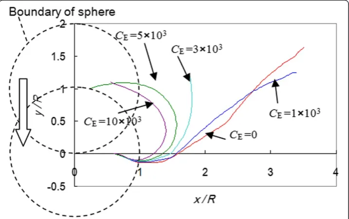
As the behavior of the splash directly depends onCE, the influence of the parameter on the formation of the splash is discussed here.
Figure 6 shows the path lines of a particle, where the tip of primary splash is plotted for the various values of CE in the case of a sphere made of the acrylic resin. It is seen from the figure that the particle, creating the film, moves upward along the surface of the sphere when the value ofCEis 3000 or over. On the other hand, when the value of
CEis smaller than this value, no film-flow appears and the exfoliation of water particles causes the crown-type splash, which is not observed in our experiment with the acrylic resin. Thus, we presume that there works a kind of electrostatic attractive force between the sphere made of the acrylic resin and the water.
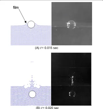
Figure 7 compares the results of the simulation in the case ofCE=5000 with the experimental results. Figure 7(A) shows the film flow rises up along the sphere at
t= 0.015 sec.
As shown in the left hand side of Figure 7(B), the primary splash by the numerical simulation at t= 0.020 sec is column-like, which is similar to the experimental result shown in the right hand side of the same figure. In the case of the column-type splash caused by the acrylic resin, the water flow does not exfoliate and the film flow rising up along the surface of sphere, which is considered to create the column-type splash. Thus, it seems appropriate to set the value ofCEto be 5000 in the case of the acrylic resin.
Although the unphysical numerical oscillation of pressure has been reported with the use of the MPS [40,41], this is found very small as far as the present simulation is concerned with any particle arrangement tested. The reason may be due to the fact that the present splash simulation is related with the behavior of the free surface and the droplet in the air and the time duration is rather short.
Effect of slip ratioαabout hydrogel
As we have discussed in Subsection 3.2, the effect of the slip ratioαon the flow around a hydrogel sphere could be taken care with Eq. (8). The comparison of the simulation result with S= 100 and the experimental one is shown in Figure 8, where the effect of
Figure 5Effect of value ofl0on crown-type splash.t= 0.03 sec andS= 100.
the attractive force discussed in the previous Subsection is not considered and the radius of sphereRis 10 mm and the initial heighthis 50Rin the both simulation and experiment. The width and the height of the splash and the fusiform air cavity are compared well between the simulation and the experiment as shown in Figure 8(A). The hourglass cavity is also simulated well as shown in Figure 8(B).
Figure 9 shows the crown-type splash and the path trajectories of particles for the dif-ferent swelling ratios. The dotted solid lines are the path trajectories of particles when
S is 50 orα= 0.94, whereas the dotted lines those whenS is 350 or α= 0.7. It is seen from the figure that the splash is wider with larger value ofSorα, or the velocity of the water near the wall is larger with the swelling ratio, which causes the earlier exfoliation, creating the wider primary splash.
Behavior of primary splash and flow pattern around sphere of hydro-gel
It is known difficult to observe experimentally which water particles originally stored in a tank cause the primary splash. Since the seed particles in the water are mixed with the air
Figure 8Comparison between simulation and experiment for hydrogel sphere (S= 100).
bubbles of the splash, it is almost impossible to trace the movement of them in an experi-mental environment such as PTV.
Figure 10 shows the path lines of some ten representative particles, which are origin-ally located at the surface or near the surface of water att= 0, when the falling object touches the surface of the water. This figure indicates that the water particles, which are originally located near the surface of the water and under the falling sphere, become the primary splash and after exfoliating from the surface of the sphere, form the tip droplet of the crown-type splash.
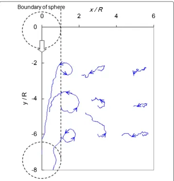
The flow induced by the crown-type splash of the hydrogel sphere is shown in Figure 11, where the path lines of representative particles are depicted betweent= 0 to 0.5 sec. while the sphere sinks in a water tank after plunging to the surface of the water. The arrows of the path lines indicate the direction of the moving particles. It is seen from the figure that the particles turn around and return to their initial positions and the loci of the particles located near the contact point draw a larger circle compared with those of the particles far from the contact point.
Conclusions
Proposed in the present paper is a new method to calculate the formation of a splash induced by a spherical object diving into water. Considering the difference of surface condition, we calculate the splash generated with a sphere by the MPS method, where the attractive force is applied to the particles located at the interface between the falling object and the water, and the swelling ratio is introduced to simulate a slip condition.
The numerical results of a diving sphere made of the acrylic resin or made of the hydrogel are in good agreement with the splash forms by the experiments. Due to the effect of the attractive force between the wall and the water, it is seen that the water film climbs along the surface of the acrylic resin sphere.
Using the slip ratio according to the magnitude of the swelling, which is the ratio of the total mass to that of the agar, the formation process of the water splash is investi-gated, finding that the hydrophilicity affects the shape of the crown during the water
splash phenomenon and the velocity of the water near the wall is larger with the swelling ratio, which causes the earlier exfoliation, creating the wider primary splash.
The simulation result shows that the particles of the water under and near the loca-tion, where the sphere plunged, become the droplets of the primary splash and that the particles of the water near a sinking sphere move around their initial positions in a circular manner.
Competing interests
The authors declare that they have no competing interests.
Authors’contribution
MY and GY are among the simulation team. YK, KK and OM are members of the experimental team. All authors have read and approved the final manuscript.
Acknowledgement
This research was supported by the MEXT supported Program for the Strategic Research Foundation at Private Universities, 2012–2017 and the WCU (World Class University) Program through the Korea Science and Engineering Foundation funded by the Ministry of Education, Science and Technology (R33-2008-000-10027-0).
Author details
1
School of Information Science, Meisei University, 2-1-1 Hodokubo, Hino, Tokyo 191-8506, Japan.2Center for Biomedical Engineering Research, Toyo University, 2100 Kujirai, Kawagoe, Saitama 350-8585, Japan.3Faculty of Science
and Engineering, Toyo University, 2100 Kujirai, Kawagoe, Saitama 350-8585, Japan.4Center for Computational Mechanics Research, Toyo University, 2100 Kujirai, Kawagoe, Saitama 350-8585, Japan.
Received: 16 September 2013 Accepted: 12 March 2014 Published: 4 April 2014
References
1. Idelsohn SR, Marti J, Souto-Iglesias A, Oñate E (2008) Interaction between an elastic structure and free-surface flows: experimental versus numerical comparisons using the PFEM. Comput Mech 43–1:125–132
2. Saksono PH, PerićD (2006) On finite element modelling of surface tension Variational formulation and applications–Part I: Quasistatic problems. Comput Mech 38–3:265–281
3. Angeles J, Thomson M (1989) Profile determination of a drop of liquid under surface tension, gravity and centrifugal forces. Comput Mech 4–5:29–344
4. Takizawa K, Bazilevs Y, Tezduyar TE (2012) Space-time and ALE-VNS Techniques for patient-specific cardiovascular fluid–structure interaction modeling. Arch Comput Methods Eng 19:171–225
5. Borghi A, Wood NB, Mohiaddin RH, Xu XY (2008) Fluid–solid interaction simulation of flow and stress pattern in thoracoabdominal aneurysms: A patient-specific study. J Fluids Struct 24:270–280
6. Khanafer KM, Bull JL, Berguer R (2009) Fluid–structure interaction of turbulent pulsatile flow within a flexible wall axisymmetric aortic aneurysm model. Eur J Mech-B/Fluids 28:88–102
7. Tallec PL, Gerbeau JF, Hauret P, Vidrascu M (2005) Fluid structure interaction problems in large deformation. C R Mecanique 333:910–922
8. Gerbeau JF, Lelièvre T (2009) Generalized Navier boundary condition and geometric conservation law for surface tension. Comput Methods Appl Mech Eng 198:644–656
9. Yokoyama M, Mochizuki O (2009) Deformation of a fluid-filled compliant cylinder in a uniform flow. J Fluids Struct 25:1049–1064
10. Yabe T, Chinda K, Hiraishi T (2007) Computation of surface tension and contact angle and its application to water strider. Comput Fluids 36:184–190
11. Takizawa K, Yabe T, Tsugawa Y, Tezduyar TE, Mizoe H (2007) Computation of free-surface flows and fluid–object interactions with the CIP method based on adaptive meshless soroban grids. Comput Mech 40:167–183 12. Zhu Q, Wolfgang MJ, Yue DKP, Triantafyllou MS (2002) Three-dimensional flow structures and vorticity control in
fish-like swimming. J Fluid Mech 468:1–28
13. Ling SC, Ling TY (1974) Anomalous drag-reducing phenomenon at a water/fish-mucus or polymer interface. J Fluid Mech 65:499–512
14. Kikuchi K, Mochizuki O (2010) A flow on a hydrogel surface mimicked a living cell. Proceeding of The 21st International Symposium on Transport Phenomena. Kaohsiung City, Taiwan (CD-ROM)
15. Manservisi S, Scardovelli R (2009) A variational approach to the contact angle dynamics of spreading droplets. Comput Fluids 38:406–424
16. Tanaka Y, Washio Y, Yoshino M, Hirata T (2011) Numerical simulation of dynamic behavior of droplet on solid surface by the two-phase lattice Boltzmann method. Comput Fluids 40:68–78
17. Muradoglu M, Tasoglu S (2010) A front-tracking method for computational modeling of impact and spreading of viscous droplets on solid walls. Comput Fluids 39:615–625
18. Liu J, Koshizuka S, Oka Y (2005) A hybrid particle-mesh method for viscous, incompressible, multiphase flows. J Comput Phys 202:65–93
19. Caboussat A (2006) A numerical method for the simulation of free surface flows with surface tension. Comput Fluids 35:1205–1216
20. Rebouillat S, Liksonov D (2010) Fluid–structure interaction in partially filled liquid containers: A comparative review of numerical approaches. Comput Fluids 39:739–746
21. Idelsohn SR, Onate E, Pin FD (2003) A Lagrangian meshless finite element method applied to fluid structure interaction problems. Comput Struct 81:655–671
22. Alam A, Kai H, Suzuki H (2007) Two-dimensional numerical simulation of water splash phenomena with and without surface tension. J Mar Sci Technol 12:59–71
23. Worthington AM (1882) On Impact with a Liquid Surface. Proc R Soc Lond A Math Phys Sci 34:217–230 24. Krechetnikov R, Homsy GM (2009) Crown-forming instability phenomena in the drop splash problem. J Colloid
Interface Sci 331:555–559
25. Truscott TT, Techet AH (2009) Water-entry of Spinning Spheres. J Fluid Mech 625:135–165
26. Kubota Y, Mochizuki O (2009) Splash Formation by a Spherical Object Plunging into Water. J Vis 12:339–345 27. Bussmann M, Chandra S, Mostaghimia J (2000) Modeling the splash of a droplet impacting a solid surface. Phys
Fluids 12:3121–3132
28. Akers B, Belmonte A (2006) Impact dynamics of a solid sphere falling into a viscoelastic micellar fluid. Non-Newtonian Fluid Mech 135:97–108
29. Duez CY, Clanet C, Bocquet L (2007) Making a splash with water repellency. Nat Phys 3:180–183
30. Harada T, Suzuki Y, Koshizuka S, Arakawa T, Shoji S (2006) Simulation of Droplet Generation in Micro Flow Using MPS Method. JSME Int J Series B 49:731–736
31. Xie H, Koshizuka S, Oka Y (2004) Numerical Simulation of Liquid Drop Deposition in Annular-Mist Flow Regime of Boiling Water Reactor. J Nucl Sci Technol 41:569–578
32. Nomura K, Koshizuka S, Oka Y, Obata H (2001) Numerical Analysis of Droplet Breakup Behavior using Particle Method. J Nucl Sci Technol 38:1057–1064
33. Wang W, Huang Y, Grujicic M, Chrisey DB (2008) Study of Impact-Induced Mechanical Effects in Cell Direct Writing Using Smooth Particle Hydrodynamic Method. J Manuf Sci Eng 130:021012-1-10
35. Beebe DJ, Moore JS, Bauer JM, Yu Q, Liu RH, Devadoss C, Jo BH (2000) Functional hydrogel structures for autonomous flow control inside microfluidic channels. Nature 404:588–590
36. Alupeia IC, Marcel Popa M, Hamcerencu M, Abadiec MJM (2002) Super absorbant hydrogels based on xanthan and poly(vinyl alcohol): 1. The study of the swelling properties. Eur Polym J 38:2313–2320
37. Li S, Liu WK (2002) Meshfree and particle methods and their applications. Appl Mech Rev 55:1–34 38. Japan Society of Mechanical Engineers (2006) JSME Mechanical Engineers' Handbookα6 Computational
Mechanics. JSME, Tokyo, Japan pp 100–101, in Japanese
39. Martin JC, Moyce W (1952) An experimental study of the collapse of liquid columns on a rigid horizontal plane. Phil Trans Royal Soc 244:312–324
40. Kondo M, Koshizuka S (2011) Improvement of stability in moving particle semi-implicit method. Int J Numer Methods Fluids 65:638–654
41. Khayyer A, Gotoh H (2011) Enhancement of stability and accuracy of the moving particle semi-implicit method. J Comput Phys 230:3093–3118
doi:10.1186/2213-7467-1-9
Cite this article as:Yokoyamaet al.:Some remarks on surface conditions of solid body plunging into water with particle method.Advanced Modeling and Simulation in Engineering Sciences20141:9.
Submit your manuscript to a
journal and benefi t from:
7Convenient online submission
7Rigorous peer review
7Immediate publication on acceptance
7Open access: articles freely available online
7High visibility within the fi eld
7Retaining the copyright to your article
![Figure 2 Schematic views (Left) and experimental results (Right) of flow profiles near no-slip wall(acrylic resin) and slippery wall (hydrogel) [14].](https://thumb-us.123doks.com/thumbv2/123dok_us/9587255.1941362/5.595.120.478.459.716/figure-schematic-experimental-results-profiles-acrylic-slippery-hydrogel.webp)