Strojniški vestnik - Journal o f Mechanical Engineering 53(2007)2, 66-77 UDK - UDC 678.033:519.61/.64
Izvirni znanstveni članek - Original scientific paper (1.01)
Modeliranje sestavov kovine in elastomerov z uporabo postopka
končnih elementov
Modelling Metal-Elastomer Composite Structures Using a Finite-Element-Method
Approach
Sergio E. Floody1 - Jorge P. Arenas2 - José J. de Espindola3
( ‘Technical University o f Chile; 2Austral University o f Chile; 3Federal University o f Santa Caterina, Brasil)
Sestavi kovine in elastomerov so pomembno orodje za zmanjšanje mehanskih nihanj. Pri upogibu nihajoči sestav lahko dušimo z dodatkom primerne plasti dušilnega materiala, na primer elastomero, kjer j e plast izpostavljena ciklični deformaciji in na ta način tudi izgubi energije. Vendar pa prisotnost elastomero pomeni, da je sestav odvisen od frekvence, zaradi tega težko natančno napovedujemo, saj je težko izračunati rešitev ustreznega problema lastnih vrednosti. V prispevku j e predstavljena metodologija za modeliranje sestavov kovine in elastomerov z uporabo metode končnih elementov. V nadaljevanju j e obravnavana računska metoda določitve približne rešitve frekvenčno odvisnega problema lastnih vrednosti. Številčne rezultate vztrajnosti smo primerjali z rezultati preizkusa običajnega “sendvič” sestava grede. Metodo smo razširili na model in tako optimirali Stockbridgove dušilnike, ki so uporabljeni za dušenje zračnih nihanj dejanskega električnega daljnovoda. Namesto uglasitve dušilnika na neko določeno frekvenco, smo z uporabo genetskih algoritmov določili ciljno fukcijo in optimirali fizikalne izmere dušilnika. S takim postopkom smo analizirali celoten problem brez uporabe modalnega pristopa napetost-energija, kar pomeni, da ta tako modeliranje zadosti načelu vzorčnosti. Metoda j e uporabna kot orodje za načrtovanje in modeliranje sestavov kovine in elastomerov.
O 2007 Strojniški vestnik. Vse pravice pridržane.
(Ključne besede: kompoziti kovine - elastomeri, modeliranje strukture, metode končnih elementov, dušilniki vibracij)
Metal-elastomer composite structures are an important tool fo r the reduction o f mechanical vibra tions. A structure that vibrates in flexure can be damped by the appropriate addition o f a layer o f damping material, fo r example, an elastomer, where the layer undergoes cyclic strain and thereby dissipates energy. However, the presence o f the elastomer means that the structure is frequency dependent, which is a difficult case fo r obtaining accurate predictions since the solution o f the corresponding eigenvalue problem is hard to compute. In this paper a methodology fo r modelling metal-elastomer composite structures using a finite-element approach is presented. In addition, a calculation scheme to approximate the solution o f the fre quency-dependent eigenvalue problem is discussed. The numerical results fo r the inertness were compared with the experimental results fo r a classic composite sandwich beam. The method is extended to model and optimise Stockbridge absorbers used to suppress the aeolian vibrations o f an actual electrical transmis sion line. Instead o f tuning the absorber to some particular frequency, an objective function is defined and the physical dimensions o f the absorber are optimised by means o f a genetic algorithm. In this approach, the complete problem is analysed without using the modal strain-energy approach, implying that this model ling satisfies the causality principle. The method appears to be useful as a tool fo r designing and modelling metal-elastomer composite structures.
© 2007 Journal o f M echanical Engineering. All rights reserved.
(Keywords: metal elastomer composite, structure modelling, finite element methods, Stockbridge dumpers)
Metal-elastomer composite structures are an im portant tool for the reduction o f mechanical vibra
0 INTRODUCTION tions. A structure that vibrates in flexure can be
energy. Since the first successful modelling o f a metal-elastomer composite presented by Ross et al. [1], considerable attention has been paid to the pre diction o f the dynamic behaviour o f such structures. For many years, the finite element method has been used for modelling structures, and several o f its ap plications have been shown to be quite accurate. Soni [2] has presented a finite element analysis of viscoelastically damped sandwich beams, which uses a combination o f shell elements and three di mensional solids for the viscoelastic part. Another approach is to use shell elements with spring ele ments to model the elastomer [3]. This methodology has been shown to increase the speed o f the calcu lations o f the stiffness and mass matrices. Lumsdaine et al. [4] have reported a method using multi-layer elements, which has been proven to be very accu rate. Although the modelling using three dimensional solid elements is the most complete alternative to solve this kind o f problem, sometimes the computa tional cost o f formulating and solving the equations can become prohibitive.
The viscoelastic materials o f greatest practi cal interest for damping applications are plastics and elastomers. An elastomer is a soft substance that exhibits thermo-viscoelastic behaviour. Viscoelastic materials possess both elastic and viscous proper ties. For a purely elastic material, all the energy stored in a sample during loading is returned when the load is removed. Furthermore, the displacement o f the sample responds immediately, and in-phase, to the cyclic load. Conversely, for a purely viscous mate rial, no energy is returned after the load is removed. The input stress is lost to pure damping as the vi bration energy is transferred to internal heat energy. All the materials that do not fall into one o f the above extreme classifications are called viscoelastic mate rials. Some o f the energy stored in a viscoelastic system is recovered upon removal o f the load, and the remaining energy is dissipated by the material in the form o f heat.
In a metal-viscoelastic-metal structure, the bending o f the composite produces not only bend ing and extensional strains in all three layers, but also shears, primarily o f the middle (viscoelastic) layer. The shear-strain energy storage tends to dominate the damping action o f the constrained viscoelastic lay ers. Many practical applications operate on the prin ciple o f constrained layer damping. The shear forces in the constrained viscoelastic layer cause the en ergy o f the vibration to be converted into heat.
Undamped metal structures normally have a very low loss factor, typically in the range 0.001 to 0.01. Using a viscoelastic layer can increase this loss factor. This means that the amplitude o f the reso nant vibration when the structure is subjected to structure-borne sound or vibration will be much lower than for an undamped structure. A reduced ampli tude o f vibration means less radiation o f sound, and also a reduced risk o f fatigue failure [5].
A characteristic o f viscoelastic materials is that their Young’s modulus is a complex quantity, having both a real and imaginary component. Fur thermore, this complex modulus varies as a function o f many parameters, the most important o f which are the frequency and temperature o f a given applica tion. Consequently, this results in a corresponding eigenvalue problem in which the stiffness matrix depends on both the frequency and the tempera ture. The moduli typically take on relatively high values at low temperatures and/or high frequencies but take on comparatively small values at high tem peratures and/or low frequencies. It is therefore necessary to establish an accurate understanding o f the influence o f these parameters in order to de sign effective damping treatments.
In general, the vibration analysis o f a system that is frequency independent can be accurately achieved by classical techniques. It is much more dif ficult to obtain accurate predictions when the equa tions o f motion are frequency dependent. This is be cause the solution o f the corresponding eigenvalue problem is difficult to compute. Methods based on the modal strain energy have been used to approxi mate the solution o f the problem [2]. However, they are not accurate when the frequency and temperature ranges are increased, and when they include the tran sition region, where the variations of the dissipation and the stiffness o f the viscoelastic material are quite pronounced. The greatest loss factors occur in the transition region at intermediate frequencies and tem peratures. On the other hand, some o f the assump tions used by these methods do not fit the principle o f causality for physical systems [6],
1THEORY
The theory o f finite elem ent methods has been clearly presented by several authors ([7] to [9]), so it will not be repeated here. However, a method to avoid inverting matrices o f a large size will be discussed in this section, since it is quite useful to speed up the numerical solution.
As a result o f the modelling using finite ele ments o f a metal-elastomer structure, a frequency- dependent equation o f motion is obtained. The equa tions o f m otion as a function o f frequency for a forced multi-degree-of-ffeedom system and its as sociated eigenvalue problem can be written as:
[ - n2M + K ( n ,r ) ] q ( f i ,r ) = f(n ) 0 ), and
K ( n ,r ) ( p ( n ,r ) = a (fi,r )M < p (n ,r ) (2), where Q is the angular frequency, T is a fixed tem perature, M is the mass matrix, K (Q ,7) is the stiff ness matrix, q(Q,7) is the modal displacement vector, f(Q) is the vector o f external forces, cp( Q ,7) is an eigenvector associated w ith the vibration modes, and o(Q,T) is an eigenvalue associated with a natu ral frequency.
In general, a direct solution o f Eq. (2) will in volve an expensive and inefficient method because of the large size o f the matrices. Therefore, a proposed algorithm to simplify the task can be summarized as: 1) Solve the eigenvalue problem o f order n for an arbitrary fixed frequency Q 0, and for a value o f tem perature T, given by:
K ( n0,r )(p (n0, r ) = a ( n0,r)M (p (Q0, r ) (3)
Now, the modal matrix d>0 has the following properties:
® orM 0 0 =I„ (4),
and
<S>T0K ( n 0,T)<t>0 = X0 (5),
where the superscript T denotes the transpose, I n is the rvxn identity matrix, and =diag(cr) is a diago nal matrix o f eigenvalues.
2) Let ó f be an nx fi truncated m atrix o f the n eigenvectors associated with the m inor eigenvalues ( « < « ) . For a frequency Q ^ Q (), the following prod uct is calculated:
ò 0r K ( n , r ) è 0 = i : ( n , r ) (6),
where the matrix Z(Q,7) is not necessarily diagonal, but it is an fix fi matrix. Then, the new eigenvalue problem can be stated as:
s ( n , 7 ’)»|/(£2,r) = /i(n ,7 ’) i|/( n ,r ) (7), 'Fr ( n , r ) > p ( n ,r ) = iÄ (8), and
' p r ( n , r ) 2 ( n , T ) ' P ( n , r ) = A ( n , r ) ( 9 ) ,
where M i\T ) and V|/(Q,7) are the eigenvalue and eigenvector, respectively, I■ is the fix fi identity m a trix , lP ( Q ,r ) is a m o d al ‘m a trix , and A (Q ,7)=tr(l.(Q ,7)) is a trace matrix o f eigenvalues. The new eigenvalue problem is still frequency de pendent, but it is a problem o f smaller size and con sequently requires less computation time.
3) Consider the following transformation o f coordi nates:
q ( n ,r ) = ® 0r ( n , r ) (10), and
r( n ,7 ,) = Y ( n , r ) p ( n , r ) ( n ) .
Substituting Eq. (10) and (11) into Eq. (1), and pre-multiplying by [fl>0f'(fi,7 ’)] gives
[ -
q2
i, + A(n,r)]p(Q,r) = [ è 0v (n ,r )]rf(n) (12).
Thus, the nodal displacement vector is given by:
q (fi, T) = 0>0<F (a, T) [-fi2I . + A (fi, T)J ‘ [ 0 0<P (fi, T) J f(fi) (13) . Therefore, the receptance matrix is obtained from Eq. (13) as:
a ( f i,r ) = è 0' F ( f i ,r ) [ - n 2i . + A (n ,7’)]"1 [ è 0T ( n ,r ) ] 7' (14) . Defining the matrix product S (fi,7’) = <t>04'(Q,7’),E q. (14) can be re-written as:
a (Q,t) = s ( n , r ) [ - n % + a(ci,t)]"‘ s r (q,t) ( i5), where X(Q,7) = A(Q,7) for all Q and T. Consequently, the inertness matrix is:
-n
2
a(n,r)=-fi
2
s(n,r)[-n
2
i.+A(fi,r)]"'sr(D,r)
(16). Then, the corresponding elem ents o f the receptance matrix a(Q ,7 ) are:
« , ( a r ) =^ Sik(n,T)sJk(n,T)
where s is an element of the matrix S(Q,7), and = o-/Q,7).
Therefore, the h x h matrix E(Q,7) can be as sumed to be a projection o f the stiffness matrix into an approximated subspace o f the space formed by the real eigenvectors. So the quality o f the approxi mation depends on the subspace, or span {<por.. tp0h}. An important detail for stating the problem o f Eq. (1) is the construction o f the stiffness matrix K(Q,7). This construction can be done by using the finite element method for each frequency. If K(Q, 7) is a matrix o f large size, it can be computed for sev eral frequencies by means o f a Taylor series expan sion in the neighbourhood o f a transition frequency Q ( as:
K( T> , 7 > f j K— (18),
where
K <->(n,r) = ^ p ^ ! (19).
It is then relatively easy to compute the de rivatives K("°(E!,,7) since only the elementary stiff ness matrices o f the viscoelastic part are frequency dependent, w hile the derivatives o f the stiffness matrices o f the metal part are not. The use ofM=3 for the series expansions shows that the results are quite exact for a narrow frequency band in the neighbour hood o f a transition frequency.
2 RESULTS
2.1 Composite Sandwich-Beam
The first example o f the application o f the theory presented above is a simple clamped-free composite sandwich beam. This kind o f structure is commonly used as a study object. The sandwich beam is made o f two metal layers o f steel 1020 and a viscoelastic core m ade o f DYAD 601 m aterial (Soundcoat Co.). The viscoelastic core was attached in between the metal layers by means o f an
epoxic-stru c tu ra l ad h esiv e. The p ro p e rtie s o f th is viscoelastic material were presented in reference [10]. The beam was 211.85 mm long and 11.97 mm wide. The thickness o f each metal layer was 2.14 mm and the thickness o f the viscoelastic core was 0.5 mm. All the dimensions o f the sandwich composite beam are in accordance to the requirements o f the ASTM E 756-98 standard [11],
The composite sandwich beam was divided into 114 two-dimensional Lagrangian solid elements on a plane state o f stress. Along the beam 19 ele ments were selected at equal intervals and each layer was divided into two elements, resulting in a total o f 507 nodes, having two degrees o f freedom at each node, so «=1014 for this application. The above pa rameters o f the structure were selected because they assured the determination o f the first four modes and the modal damping produced by the shear de formation o f the core.
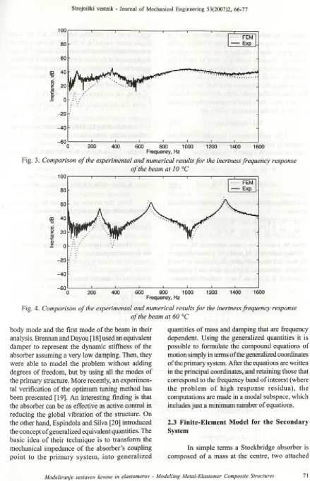
An experimental set-up was devised to per form a dynamic test to measure the frequency re sponse of the beam. The beam was excited using a magnetic actuator (B&K MM0002). The signal fed to the actuator was a chirp excitation between 0 to 1600 Hz, i.e., a sine wave o f linearly increasing fre quency, and amplified by a power amplifier (B&K 2706). The response o f the beam was measured by a small accelerometer (B&K 4375). The signals were analysed using a two-channel FFT analyser (HP 3567A). The experimental set-up was placed inside a chamber in which the temperature could be control led in the range between -3 0 and 60°C. The preci sion o f the chamber was ±1°C. The excitation was applied at 59.64 mm from the clamped edge, which corresponds to node 143 in the finite element mesh, and the response was measured at 37.95 mm from the clamped edge, which corresponds to node 91 in the finite element mesh (see Fig. 1).
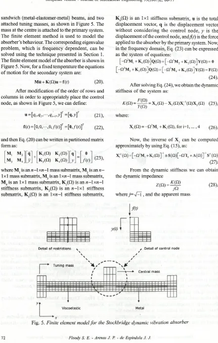
Computation o f the inertness was developed for different temperatures ranging between -3 0 and 60°C, and they were compared with the results ob tained experimentally. In the computation h =50 was used for the theory presented in Section 1. Figures 2
Response (9 1 ) Excitation (1 4 3 )
to 4 show the results o f the inertness for three differ ent temperatures.
From the results the effect on the natural fre quencies caused by the increase in stiffness o f the elastomer in the transition region (-10°C < T< 20°C) can be seen. In fact, in this region, the value o f the fourth natural frequency increased so much that it fell out o f the frequency range o f the measurement. There is rea sonable agreement between the numerical and experi mental results for the inertness frequency responses presented in Figures 2 to 4, although it is observed that the numerical results seem to underpredict the natural frequencies when compared with those obtained from the experimental set-up. The differences are on aver age about 6%. Nevertheless, the differences between the numerical and experimental approaches can be due to imperfections in the experimental fixture, the small size o f the structure under test, the contribution o f the off-resonant modes, and the measurement uncertainty produced by the environment inside the chamber. The effect o f the chamber should be more pronounced in the transition region, where small variations o f tem perature will cause large variations on the elastic prop erties o f the elastomer. The value o f the humidity inside the chamber was not accurately controlled during the experiment. This fact was reflected as noise in the meas ured inertness frequency-response curves, as seen in Figures 2 to 4.
2.2 Stockbridge Dynamic Vibration Absorber
In this section the theory will be applied to a m ore complicated case, i.e., a Stockbridge dynamic
vibration absorber. The vibration absorber will be viscoelastically m odified in order to increase the dissipation o f vibrational energy.
A dynamic vibration absorber, also called a v ib ra tio n n e u tra liz e r, is a dev ice o r stru ctu re (secondary system ) th at is attached to another device (primary system) to reduce vibration levels. It acts on the primary system by applying reaction forces and dissipating vibration energy. Vortex- induced or aeolian vibrations o f overhead electrical transmission lines, also referred to as conductors, are very common and can lead to fatigue damage. T hese v ib ratio n s are u su ally caused by w inds ranging in velocity from 1 to 7 m/s and can occur at frequencies from 3 to 150 Hz with peak-to-peak displacem ent amplitudes o f up to one conductor diameter. In conventional transmission line systems, one or more Stockbridge absorbers may be attached to a conductor in an effort to suppress the aeolian vibrations ([12] and [13]).
The classic theory introduced by den Hartog [14] for a viscous vibration absorber, called MCK, and th eir extensions to a viscoelastic absorber, presented by Snowdon [15], are difficult to apply. This is because for complex mechanical systems many modes can contribute to the total response of the primary system. Interesting methods to optimise dynamic vibration absorbers have been presented by Brennan and co-workers ([16] to [19]). Kidner and Brennan [17] used a multi-degree-of-freedom beam neutralizer with piezoceramic patches as active elements, and they analysed the improvement on the performance o f the absorber considering the rigid
100 80 60 m 40
■o
0)
c 20
<0 r 5
— 0
-2 0
-40 -60
0 200 400 600 800 1000 1200 1400 1600
Frequency, Hz
Fig. 3. Comparison o f the experimental and numerical results fo r the inertness frequency response o f the beam at 10 °C
Fig. 4. Comparison o f the experimental and numerical results fo r the inertness frequency response o f the beam at 60 °C
body mode and the first mode o f the beam in their analysis. Brennan and Dayou [ 18] used an equivalent damper to represent the dynamic stiffness o f the absorber assuming a very low damping. Then, they were able to m odel the problem without adding degrees o f freedom, but by using all the modes o f the primary structure. More recently, an experimen tal verification o f the optimum tuning method has been presented [19]. An interesting finding is that the absorber can be as effective as active control in reducing the global vibration o f the structure. On the other hand, Espindola and Silva [20] introduced the concept o f generalized equivalent quantities. The basic idea o f their technique is to transform the mechanical impedance o f the absorber’s coupling p o in t to the p rim ary system , into generalized
quantities o f mass and damping that are frequency dependent. Using the generalized quantities it is possible to formulate the compound equations of motion simply in terms o f the generalized coordinates o f the primary system. After the equations are written in the principal coordinates, and retaining those that correspond to the frequency band o f interest (where th e p ro b le m o f hig h re sp o n se re sid u a ), the computations are made in a modal subspace, which includes just a minimum number o f equations.
2.3 Finite-E lem ent Model for the Secondary System
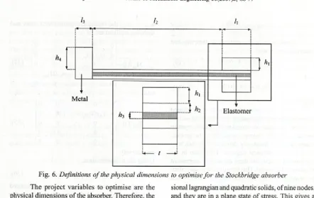
sandwich (metal-elastomer-metal) beams, and two attached tuning masses, as shown in Figure 5. The mass at the centre is attached to the primary system. The finite elem ent m ethod is used to m odel the absorber’s behaviour. The corresponding eigenvalue problem , w hich is frequency dependent, can be solved using the technique presented in Section 1. The finite element model o f the absorber is shown in Figure 5. Now, for a fixed temperature the equations o f m otion for the secondary system are:
Mii + K(Q)u = f(0 (20).
A fter modification o f the order o f rows and columns in order to appropriately place the control node, as shown in Figure 5, we can define:
« = (21),
f (0 = [0, o, • • •, 0, / ( o f = [o, /(O f
(22),
and then Eq. (20) can be written in partitioned matrix form as:
M, M 2‘ q
_i_ "K,(fi) k2(Q)_ q 0 m3 m4_ y . k3(0 ) k4(£1). y .
where Mj is an «-1 xn-1 mass submatrix, M2 is an n- 1X1 mass submatrix, M3 is an 1 x « - l mass submatrix,
m4 is an l x l mass submatrix, K ,(Q ) is an n - lx n - 1 stiffness subm atrix, K2(Q) is an « - l x l stiffness submatrix, is an l x « - l stiffness submatrix,
K4(Q) is an l x l stiffness submatrix, u is the total displacement vector, q is the displacement vector w ithout consid erin g the control node, y is the displacement o f the control node, and/(f) is the force applied to the absorber by the primary system. Now, in the frequency domain, Eq. (23) can be expressed as the system o f equations:
[ - n 2M, + K, (Q)] Q(Q) + [ - n 2M 2 + K 2 (£2)] Y(Q) = 0
[ - n 2M 3+k3 (n>] Q (Q )+ [ -q2m4+k4 (Q)] Y (n )=f(£2)
(24). After solving Eq. (24), we obtain the dynamic stiffness o f the system as:
* ( « ) = = X<(n ) " X3 ( W (0)X2 (£1) (25),
where:
X,.(£2) = - £ 2 2M , + K ,.( Q ) , f o r i = l ...4 ( 2 6 ) .
Now, the inverse o f X | can be com puted approximately by using Eq. ( 15), as:
X“1 (Q) = + K,(£2)]"' s S(£2)[-£2% + A(Q)] ' Sr (£2) (27). From the dynamic stiffness we can obtain the dynamic impedance
Z(£2) = ® (28),
J& where j ~ 4- \ , and the apparent mass
f it)
s
\
M ( f i ) =K ( fi)
- f i
2
(29).Consequently, the equivalent damping and equivalent mass are
ce,(n)=9?{z(n)}
po)
and
meq(n)=m{M(ci)} (31))
respectively.
Then, the model o f the absorber is replaced by an equivalent mechanical system composed o f an equivalent mass connected to the primary system and an equivalent damper connected to the ground, where both are frequency dependent. In this way there are new physical degrees o f freedom in the mechanical system, but there are no new degrees o f freedom in the model. This formulation is equivalent to the simple model o f a Stockbridge absorber, which makes use o f the Euler-Lagrange equations.
2.4 Optimisation of the Stockbridge Absorber
Now, the secondary system (Stockbridge absorber) is attached to a primary system (electrical transmission line) resulting in a compound system. In order to optimise the physical dimensions o f the absorber, an objective function has to be proposed. Here, the objective function will be defined from the maximum absolute values o f the principal coordinate functions o f the compound system. Assuming that the prim ary system has a very low and alm ost co n stan t h y steretic dam ping, the equations o f m otion for the prim ary system in the frequency domain are:
[ - f i 2M p, + K „ ] q pr(fi) = f(fi) (32), where Mpr is the mass matrix o f the primary system, K is the complex stiffness matrix o f the primary sy stem , q (Q ) is th e d isp la c e m e n t v e c to r o f generalized coordinates, and f(Q) is the force vector. U sing the theory o f the equivalent generalized q u an tities [20], the com pound system can be modelled as:
[ - f i 2 [ M pr + (fi)] + yfiC e, (fi) +
Kpr ] qpr
(fi) = f (fi) (33), where M (Q) is the equivalent mass matrix and C e (Q) is the equivalent damping matrix.I f p absorbers are attached to the primary system, at the generalized physical coordinates qkl,
qkV ... , qtp, the equivalent generalized mass and damping matrices are:
M T f i ) =
0 0
0 " % ( %
0 0 0 0 0 0 and 0 0 0 0 0 0 (ft)* 0 0 0 (34), C„(fi) = 0 0 0 0 0 0 0 0 0 respectively.
Using the transformation:
0 0
0 0
0 0
( f t ) * 0
0 0
(35),
q „ ( « ) = < iV M Q) (36)> where O is the matrix of the eigenvectors associated with the eigenvalues o f the primary system in the frequency band o f interest, and p;„ is the vector of the principal coordinates of the primary system, Eq. (33) can be written as:
[ - f i 2 [I + M ,(fi)] + yfiC,(fi) + E„
]ppr
(fi) = n(fi) (37), where M , ( Q ) = 0 ^ ( Q ) 0 pr, C ,(Q )= ® /C/Q)<b ,n(Q)=<J> rf(Q), and I = 0 TC O =tr(cr) is a trace m atrix o f eigenvalues o f the prim ary system . Consequently:
ppr (fi) = [ - f i2 [I + M , (fi)] + ja C A (fi) + J ' n(fi)
(38) , and the receptance matrix can be calculated by:
«(fi) = «V [ - ^ 2 [I + M , (fi)] + y fiC , (fi) + £ pr J ' < (39) . Then, in order to solve the optim isation problem it is possible to define an objective function / as the modulus o f a vector formed by the maximum a b so lu te v a lu e s o f the g e n e ra liz e d p rin c ip a l coordinates o f the primary system [20], This can be expressed by the equation:
|p;r(x,fi)|| (40),
where Q, and Q, are the lower and upper limits of the frequency band o f interest, respectively, x is a design vector o f project variables to optimise, and z'=l,..., N, where N is the total number o f degrees of freedom o f the primary system.
/0 0
=h li l,
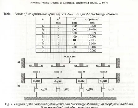
Fig. 6. Definitions o f the physical dimensions to optimise fo r the Stockbridge absorber The project variables to optim ise are the
physical dimensions o f the absorber. Therefore, the design vector is defined as:
X =[A
,i2f A A ’K K ’t f
(41),where the elements o f x are the physical dimensions shown in Fig. 6. The constraint functions are defined for each element o f x as:
x - < Xl<xf (42),
where xf- and x f are the lower and upper limits for each element, respectively. For the force vector, a unit force at each excitation point o f the primary system can be used, i.e., f=[l, 1,..., 1,1 ]
T.
A numerical example was performed for a real com pound system . A total o f four Stockbridge absorbers were attached to the primary system. In this exam ple o f a Stockbridge absorber the two sandwich beams are designed from two metal layers o f steel 1020 and a viscoelastic core DYAD 601 (Soundcoat Co.). The finite element model o f the absorber is shown in Fig. 5. The beams were divided into 114 elements. For the length and thickness o f the core, 19 and 2 elements were used, respectively. T his c h o ic e w as fo u n d a p p ro p ria te fo r b o th , rep resen tin g e ffic ie n tly the in tern al sh ear and determining the first four modes in the frequency band used. The mass at the centre was divided into 32 elements and the tuning masses were divided into 24 elem en ts each. T h is choice is b e cau se the mechanical purposes o f the masses do not require high discretization. All the elements are two-dimen
sional lagrangian and quadratic solids, o f nine nodes, and they are in a plane state o f stress. This gives a total o f 308 elements, 1319 nodes, and a total o f «=2638 degrees o f freedom. For simplicity, the temperature is assumed to be a constant.
T he p rim ary system co n sid ered w as an ACRS partridge cable, 30.2 m long, clamped at both extremes and subjected to a tension o f 9000 N. The cable was divided into 81 equally spaced elements. The central masses o f the absorbers were attached at nodes 5, 35, 46, and 76 o f the cable. These positions were selected in order to be far from the nodes o f the cable, allowing the absorbers to control a large number o f modes o f the primary structure. Figure 7 shows the physical model o f the compound system and its corresponding generalized equivalent quantities model.
Table 1. Results o f the optimisation o f the physical dimensions fo r the Stockbridge absorbers
Xi xi optimised
mm mm mm
h 0 200 10.321
h 0 1000 210.002
h 0 200 30.024
hx 0 100 10.096
h2 0 10 2.013
h 0 5 2.000
h4 0 400 30.102
t - - 10.000
ACSR Cable
Node 5 Node 35 Node 46 Node 76
Fig. 7. Diagram o f the compound system (cable plus Stockbridge absorbers): a) the physical model and b) its generalized equivalent quantities model
were explained in detail in the literature [21] to [23]. The numerical results o f the optimisation process are presented in Table 1.
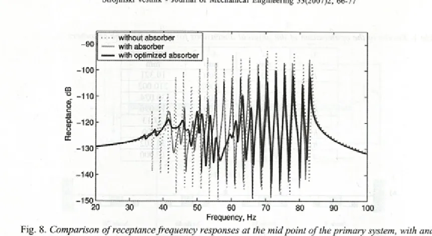
Figure 8 shows the results o f the receptance at the mid point o f the cable, when no absorber is attached, and when the absorbers are attached to the cable before and after the optimisation process. It can be seen that after their dim ensions were optimised, the Stockbridge absorbers reduced the vibration level o f the cable in a very effective way. M ost o f the peak values o f the receptance frequency response were attenuated and for the peak value at around 60 Hz an attenuation o f 30 dB was achieved after the optimisation.
3 CONCLUSIONS
The modelling o f a metal-elastomer compos ite structure based on a finite element method has been presented. In addition, a methodology to re duce the computation time when dealing with fre quency dependent matrices has proven to give good approximate results. It has to be noted that the pre cision o f the approximation presented in Section 1
—150*--- '---1--- '— —4— I---!— ' ...
1---20 30 40 50 60 70 80 90 100
Frequency, Hz
Fig. 8. Comparison o f receptance frequency responses at the mid point o f the primary system, with and without an optimised Stockbridge absorber
theory could be extended to other kinds o f absorb ers. M oreover, the use o f generalized equivalent quantities allows one to define an objective func tion o f the maximum absolute values o f the principal coordinates o f the primary structure. This objective function is independent o f the geometry o f the pri mary system and it is dependent on its modal param eters. The application o f the method to Stockbridge absorbers used to suppress the aeolian vibrations o f a real electrical transmission line shows that the
reduction in the response o f up to eleven modes is achieved after the dimensions o f the absorbers are o p tim is e d u sin g a g e n e tic alg o rith m . T he optimisation process can be quite slow when com pared to other techniques reported in the literature [18] and [19]; however, the results presented in this work seem to be encouraging. Further work will be conducted regarding the computational costs and detuning o f the absorber due to the presence o f tem perature changes in the elastomer layer.
4 REFERENCES
[1] Ross D., E.E. Ungar, E.M. Kerwin Jr. (1959) Damping o f plate flexural vibrations by means o f viscoelastic laminate structural damping, in Structural Damping, ASME, New York, pp. 49-88.
[2] Soni, M.L. ( 1980) Finite element analysis o f viscoelastically damped sandwich structures, in Proc. o f 51st Shock and Vibration Symposium, San Diego, pp. 97-109.
[3] Mignery, L. (1995) Vibration analysis o f metal/polymer/metal components, in Proc. o f ASME Design Engineering Technical Conferences, Voi. 3 (C), Boston, pp. 23-33.
[4] Lumsdaine, A., R. A. Scott ( 1995) Shape optimisation o f unconstrained beam and plate damping layers, in Proc. o f ASME Design Engineering Technical Conferences, Voi. 3 (C), Boston, pp. 15-22.
[5] Ungar, E.E. (1998) Vibration isolation and damping, Chapter 55 in Flandbook o f Acoustics (Edited by M. J. Crocker), John Wiley and Sons, New York.
[6] Crandall, S.H. ( 1991 ) The hysteretic damping model in vibration theory. Proc. o f the Institute ofMechani cal Engineers, Part C, Journal o f Mechanical Engineering Science 205(1), pp. 23-28.
[7] Hughes, T J.R . (2000) The finite element method, Dover, N ew York. [8] Bathe, K.J. (1995) Finite elements procedures, Prentice-Hall, N ew York.
[9] Petyt, M. (1990) Introduction to finite element vibration analysis, Cambridge University Press, Cam bridge.
[11] ASTM E 756-98 (1998) Standard test method for measuring vibration-damping properties o f materials, ASTM, New York.
[12] Vecchiarelli, J., I.G. Currie, D. G. Havard (2000) Computational analysis of aeolian conductor vibration with a Stockbridge-type damper. J. o f Fluids and Structures 14(4), pp. 489-509.
[13] Richardson, A.S. (1996) Performance requirements for vibration dampers. Electric Power Systems Re search 36(1), pp. 21-28.
[14] den Hartog, J.P. (1956) Mechanical vibrations, McGraw-Hill, New York, 1956.
[15] Snowdon, J.C. (1966) Vibration o f cantilever beams to which dynamic absorbers are attached. J. o f the Acoust. Soc. Am. 39(5), pp. 878-886.
[16] Brennan, M.J. (1998) Control o f flexural waves on a beam using a tunable vibration neutraliser. J. Sound andVib. 222(3), pp. 389-407.
[17] Kidner, M., M.J. Brennan (1999) Improving the performance o f a vibration neutraliser by actively remov ing damping. J. Sound and Vib. 221(4), pp. 587-606.
[18] Brennan, M.J., J. Dayou (2000) Global control of vibration using a tunable vibration neutralizer. J. Sound and Vib. 232(3), pp. 585-600.
[19] Dayou, J., M.J. Brennan (2003) Experimental verification o f the optimal tuning o f a tunable vibration neutralizer for global vibration control. Appi. Acoustics 64(3), pp. 311-323.
[20] Espindola, J.J., H.P. Silva (1992) Modal reduction o f vibrations by dynamic neutralizers: a general ap proach, in Proc. Tenth International Modal Analysis Conference, San Diego, pp. 1367-1373.
[21] Espindola, J.J., S.E. Floody (2001) Optimal design o f Stockbridge dynamic vibration neutralizer viscoelastically modified applying the finite element method, in Proc. 9th International Symposium on Dynamic Problems o f Mechanics, Florianópolis, pp. 507-513.
[22] Rechenberg, I. (1993) Evolutionsstrategie: Optimierung technischer Systeme nach Prinzipien der biologischen Evolution (Evolution strategy: optimization of technical systems by means o f principles o f biological evolution), Fromman-Holzboog, Stuttgart.
[23] Hung, S.L., H. Adeli ( 1994) A parallel genetic/neural network learning algorithm for MIMD shared memory machines. IEEE Transactions Neural Networks 5(6), pp. 900-909.
[24] Espindola, J.J., C.A. Bavastri (1999) Optimum conceptual design o f viscoelastic dynamic vibration neu tralizer for low frequency complex structures, in Proc. Int. Symposium on Dynamic Problems in Me chanic andMechatronic, Günzburg, pp. 251— 259.
[25] Lanczos, C. ( 1950) An iteration method for the solution o f the eigenvalue problem of linear differential and integral operators. Journal o f Research o f the National Bureau o f Standards 45(4), pp. 255-281.
Authors’ Addresses: Prof. Dr. Sergio E. Floody Univ. Tecnològica de Chile Brown Norte 290
Santiago, Chile
1
Prof. Dr. Jorge P. Arenas Institute o f Acoustics Univ. Austral de Chile PO Box 567, Valdivia, Chile [email protected]
S e d :
Sprejeto: 25102006 Accepted:
Prof. Dr. José J. de Espindola Dept. Mechanical Engineering Univ. Federal de Santa Caterina Florianópolis, SC 80040-900, Brasil espindol@mbox 1 .ufsc.br