© Strojniški vestnik 45C199931,25-34- © Journal of Mechanical Engineering 45C1 9 9 9 3 1 ,2 5 -3 4
ISSN 0 0 3 9 -2 4 8 0 ISSN 0 0 3 9 -2 4 S 0
UDK 62 -25 :62 1 .2 2 4 .6 :5 3 2 .5 7 UDC 62-25:621 .2 2 4 .6 :5 3 2 .5 7
Pregledni znanstveni članek C1 .023 Review scientific paper C1 .023
Vpliv sekundarnega toka na obratovalna
karakteristiko radialnega rotorja normalne
širine
Influence of Secondary Flow on the Operating Characteristics of a Radial Impeller with Normal Width
Andrej Predin
V članku so podani rezultati eksperimentalne analize vpliva dodanega sekundarnega toka na vstopu v radialni rotor normalne širine. Sekundarni tok j e dodajan skozi vodilnik, ki se končuje s kolobarjasto rego ob pokrovni steni rotorja. V kolobarjastem vodilniku so vzdolžno nameščene vodilne lopatice, ki zagotavljajo osno simetrični nevrtinčni sekundami tok na vstopu v rotor. Izvedeno j e atmosfersko (neprisilno) polnjenje s spiralnim vodilnikom, nameščenim pred kolobarjastim vodilnikom. Po eksperimentalnih rezultatih lahko sklepamo, da dodani sekundarni tok ugodno vpliva na obratovalne karakteristike radialnega rotorja normalne širine (13 < nq < 35), ker poveča stabilni del obratovanja proti manjšim obratovalnim pretokom (poveča se možnost širše regulacije), pri
tem pa se še nekoliko izboljša skupni izkoristek, predvsem v področju manjših, podoptimalnih pretokov. © 1999 Strojniški vestnik. Vse pravice pridržane.
(Ključne besede: rotorji radialni, tok sekundarni, karakteristike obratovalne, analize eksperimentalne)
In the paper an analysis o f the experimental results o f a secondary flow addition at the radial impeller entrance (normal width impeller) is given. The secondary flow is added through the guide system, which ends with the circle-ring at the impeller front shroud. The guide vanes are set in the circle-ring guide system in the direction o f the intake pipe axis. The guide-vanes assure the axi-symmetrical non-whirl secondary flow at the impeller intake. The atmospheric (non-forced) secondary flow loading is performed with the volute guide system placed at the entrance o f the circle-ring guide system. Based on the experimental results, it can be concluded that the suitable secondary flow favourably influences the operating characteristic o f the impeller (13 < nq < 35) width. The stable operating area increases in the direction o f the small operating capacities (thus giving the possibility o f wider pump control). At the same time the overall efficiency is increased, especially in the area o f small,suboptimum capacities.
© 1999 Journal of Mechanical Engineering. All rights reserved.
(Keywords: radial impellers, secondary flow, operating characteristics, experimental results)
O UVOD 0 INTRODUCTION
Radialni rotorji normalnih širin s specifičnimi števili vrtljajev med 20 in 35 min'1 imajo nestabilno obratovalno karakteristiko. To dejstvo omejuje uporabo takšnih rotoijev glede dosegajočih pretokov, predvsem z vidika manjše možnosti stabilnega obratovanja v širšem področju pretokov, ki jih dosega tak rotor. Nestabilni del leži v področju majhnih obratovalnih pretokov, kjer je tudi skupni izkoristek razmeroma slab. Znano je, da se pri takšnih rotorjih izkoristek znatno zmanjšuje od optim alnega tako v področje večjih (nadoptimalnih) kakor tudi v področje manjših (pod optimalnih) pretokov. Zato so z obratovalnega vidika zanimivi vsi ukrepi, ki bi ob minimalni spremembi geo m etrije (m ajhni stro šk i), raz širili področje obratovalnih pretokov, pri katerih bi izkoristek bil še zadovoljiv.
1 RAZVOJ DODAJANJA SEKUNDARNEGA TOKA
Prvi je vpliv dodanega sekundarnega toka proučeval Eck [ 1 ], vendar predvsem na radialnih rotorjih povečane oz. velike širine, pri čemer je dodajal tudi do tri sekundarne tokove, tudi ob pestai steni rotorja in v sredini vstopne širine rotorja. Vodilo mu je bilo predvsem doseganje mejnih obratovalnih zmogljivosti, tako po pretoku (Qmak,) kakor tudi po dosegajočih energijskih oziroma tlačnih razlikah (Ap mah), manj pa s strani razširitve ugodnega obratovalnega območja. Znana sta dva načina dodajanja sekundarnega toka, in sicer:
a) prisilna polnitev z dovajanjem sekundarnega toka na vstop rotorja oz. rotorskih lopatic ob pokrovni steni iz tlačnega cevovoda ali z drugim virom (dodatni ventilator - manj ugodno zaradi večjih izgub dodatnega pogona) in
b) prosta polnitev - dodajanje sekundarnega toka s p ro stim v sesav an jem pri tlak u o k o lice - atmosferskem tlaku (konkretno uporabljeno pri pričujočem testiranju).
Glede skupnega izkoristka celotnega sistema ima druga varianta b) prednost pred prvo a), v primerjavi naj večjih - mejnih zmogljivosti pa je v prednosti druga varianta. Tako se je treba tudi v tem primeru ustrezno odločiti, kaj želimo dosegati s konkretnim sistemom.
2 SPLOŠNE KARAKTERISTIKE TESTNEGA SISTEMA
Sistem obsega štiri osnovne sklope; pogonski, m o d eln i, sklop o ziro m a sistem za d ovajanje sekundarnega toka in dotočni sklop. Poenostavljeni model z radialnim rotorjem («,= 24 m in 1) je podrobneje predstavljen v prispevku [2].
2.1 Karakteristike sklopa sekundarnega toka
Sistem za dovajanje sekundarnega toka na vstopu v rotor ob pokrovni steni je sestavljen iz kolobarjastega vodilnika z dvajsetimi osno simetrično postavljenimi vodilnimi lopaticami v njem, ki se končuje v obliki kolobarjaste reže širine s = 0,003 m in iz spiralnega vodilnika, ki usm erja sekundarni tok v kolobarjasti vodilnik iz radialne v aksialno smer (sl. 1).Vodilne lopatice v kolobarjastem vodilniku so namenjene za osno simetrično usmerjanje toka na vstopu v rotor (preprečevanje vrtinčnosti toka), ker se dodani sekundami tok preusmerja iz spiralnega vodilnika v kolobaijasti, pri čemer se spremeni smer toka iz radialne v aksialno smer.
1 DEVELOPMENT OF THE SECONDARY FLOW ADDITION METHOD
The first person who studied the influence of the secondary flow addition was Eck [1], but his stud ies were primarily based on impellers o f large width. He then added up to three secondary flows: at the im peller hub, at the middle of the impeller width, and at the impeller front shroud. His purpose was to find a way o f increasing the maximal impeller performance in order to increase maximal operating capacities (Qmax) and/or maximal energy or pressure differences (Apmax), and less directed towards increasing the area of the suit able operating capacities. Two different principles for secondary flow addition are already known:
a) forced loading, supplying the secondary flow at the impeller entrance at the front shroud from the dis charge pipe or by other sources (an additional fan - is less suitable, because additional energy losses occur) and
b) atmospheric or non-forced loading with the second ary flow supplied by free suction from the surround ing ambient at atmospheric pressure (as used in our investigation).
Regarding the overall efficiency o f the whole testing system, the second option b) is more advanta geous than the first one a). However, when maximal capacities or maximal pressure differences are the goal, variant a) is preferable. Therefore, the decision, as to which option is optimal must made from case to case.
2 GENERAL CHARACTERISTICS OF THE TESTING SYSTEM
The testing system includes four basic parts: driving part, impeller fan-model, the system for the sec ondary flow addition, and the main intake pipe system (part). The simplified fan model has the radial impeller («, = 24 rpm), and has already been presented in [2],
2.1 Characteristics of the secondary-flow system
The system for the secondary flow addition to the impeller intake diameter at the impeller front shroud is composed o f the circle-ring guide pipe with twenty guide-vanes placed in axial-symmetric direc tion. The circle gap width o f the circle-ring guide pipe is ^ = 0.003 m. The spiral guide volute guides the sec ondary flow from the radial to the axial direction at the entrance o f the circle-ring guide pipe (Fig. 1). The guide vanes in the guide-ring guide the flow in the axial direction (attempting to prevent the flow vor tex), since the entrance flow from the spiral guide vo lute has a radial direction and has to be directed into the axial direction.
2.2 Karakteristike radialnega rotorja 2.2 The radial impeller characteristic
Rotor je izveden v radialni obliki z enajstimi (zr= 11) nazaj ukrivljenim i rotorskim i lopaticami
The fan-model has a radial im peller with eleven back-curved (zr= 11) cylindrically shaped (in
I gnnpäBy Mižečo 1
Sl. 1. Sklop za dovajanje sekundarnega toka na vstopu v rotor ob pokrovni steni Fig. 1. Secondary flow addition system at the impeller entrance at the front shroud
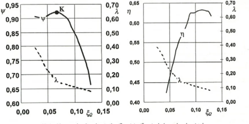
valjaste oblike (prostorsko enkrat ukrivljene lopatice) konstantne širine (bi = bi = 0,05 m). Vstopni in izstopni kot lopatic sta ßi = 23° oziroma [h = 25°. Razmerje premerov je D2/D1 = 0,6/0,36 = 1,66. Proračunska točka rotoija je pri n = 1800 m in1 in pretoku QpKr= 0,65 m3/s. O bratovalna karakteristika rotorja je podana v brezdimenzijski obliki in je nestabilne oblike (sl. 2). Brezdimenzijski koeficient - tlačno število je določeno z:
¥ =
kjer so: Ap - izmerjena tlačna razlika, ki jo rotor dosega, p - gostota toka in U2 - obodna hitrost na rotorjevem izstopnem premeru D2. Brezdimenzijski koeficient - specifični pretok je določen z:
S
fl =
kjer je Q - izmerjeni obratovalni pretok, n - vrtilna hitrost (število vrtlj aj ev na sekundo) in Eh-izstopni premer rotorj a.
Izkoristki so določani po:
space once curved) blades with a constant width (bi = fo = 0.05 m). The intake and exit blade angles, respec tively, are ßi = 23° and ßi = 25°. The impeller calcula tion point (operating point) is at « = 1800 rpm and at
Qcai = 0.65 m3/s. The operating characteristic (head- capacity curve), given in non-dimensional form, is pre sented in Figure 2. As shown, it is non-stable. The non- dimensional coefficient - pressure number is given by:
2 A p
— T (1).
p u2
where Ap is the measured pressure difference achieved by the impeller, p is the density, and U2 is the circumfer ential velocity at the impeller exit diameter Di. The non- dimensional coefficient - specific capacity is given by:
%
(2 )’nD2
where Q is the measured operating capacity, n the im peller speed (rps) and Di is the impeller exit diameter.
The impeller efficiency is determined by:
7] =
2
m M
(3),
kjer je M moment na gredi rotorja. Največji izmerjeni izkoristek znaša rj = 0,62 pri pretoku <^e= 0,118. Kritična točka, ki loči stabilni del od nestabilnega leži pri pretoku č,Q= 0,089, kjer znaša doseženo tlačno število yf= 0,860 (točka K, sl. 2 a).
where M is the impeller shaft torque. The maximal measured efficiency is r\ = 0.62 at the specific capacity £q= 0.118. The critical point that separates the stable and non-stable operat ing area (capacity-head curve) is at 0.089, where the pressure coefficient is y/= 0.860 (point K, Fig. 2 a).
2.2 Karakteristike radialnega rotorja z dodanim sekundarnim tokom
Iz posnete karakteristike - dušilne
krivulje (sl. 3 levo) je razvidna sprememba oblike . Kritična točka K (sl. 3 levo) seje pomaknila v področje manjših pretokov, konkretno na <^o,k,sst = 0,66. S tem se je območje stabilnega dela obratovalne karakteristike
( A^q= At,Q ,K - A t ß . m a f l )povečalo iz A ^q.bst = 0,041, pri
2.3 The impeller characteristic with added second ary flow
From the measured «jjg-yr characteristic capac ity-head curve (Fig. 3 left), the shape change is evident. The critical point K (Fig. 3 left) is toward smaller ca pacities (in our case to £q,k,sf = 0.660). With this criti cal point movement the stable characteristic is enlarged (A%q = A - A%Qjm) from A^q.wsf = 0.041 (no added
33-1 1____
Sl. 2. Obratovalna karakteristika (ŠQ-y ) in
Fig. 2. Capacity-Head and Capacity-Efficiency curve (t; -7])
obratovanju brez dodanega sekundarnega toka, na A^o.sst = 0,064, pri obratovanju z dodanim sekundarnim tokom , k ar k o n k retn o pom en i 56,1% relativ n o povečanje intervala. Z dodajanjem sekundarnega toka seje povečalo tudi maksimalno tlačno število (v kritični točki) iz t//k,BST = 0,86 in i//k.,sst = 0,923 , oz. za 7,3 %. Z uvedbo razmemika pretokov:
secondary flow) to A^q.sf = 0.064 when the fan oper ates with added secondary flow. In our case the stable part of the characteristic was increased by 56 % rela tively. By adding the secondary flow the maximal pres sure number (at the critical point) was increased from
i//k,wsF= 0.86 to y/k,sF= 0.923. This is a 7.3 % increase. By introducing the capacity ratio in the form of:
kjer sta qs - pretok dodanega sekundarnega toka in Qm -glavni pretok po osnovnem dovodnem cevovodu (po sesalnem cevovodu) lahko določimo delež dodanega sekundarnega toka v skupnem pretoku. Iz razmemika pretokov (sl. 3) je razvidno, da pri majhnih pretokih poteka 38% celotnega pretoka Q = Qm + qs kot dodani sekundami tok, pri naj večjih pretokih pa le še samo okrog 7%.
(5),
where qs is the capacity o f the added secondary flow and Q is the main capacity from the intake pipe sys tem (suction pipe system) the portion of the added sec
ondary flow in the common capacity Qc ~ Qm + qs can
therefore be determined. As it is clear from the capac ity ratio curve (Fig. 3), this portion is 38% at low oper ating capacities and is only 7% at high operating ca pacities.
SI. 3. Obratovalna karakteristika (ŠQ-V) in (Šg-T]), dodan sekundami tok Fig. 3. Capacity-Head (ŠQ-y ) and Capacity-Efficiency curve (£ß-rj), added secondary flow
2.4 Primerjava karakterističnih krivulj %Q-y /in £,Q-rj pri obratovanju brez in z dodanim sekundarnim tokom
Iz primerjave karakterističnih krivulj (%q-i/z) pri
obratovanju brez in z dodanim sekundarnim tokom (sl. 4 levo) je razvidno povečevanje tlačnega števila yt proti kritični točki K v stabilnem obratovalnem delu krivulje. V povprečju je doseženo tlačno število t/rpri obratovanju na stabilnem delu karakteristične krivulje (%Q-y/)z dodanim sekundarnim tokom na vstopu v rotor, večje za 5,3 % oz. višje od tlačnega števila kakor pri obratovanju brez dodanega sekundarnega toka. Največje povečevanje tlačnega števila je doseženo prav v kritični točki Kssr, in sicer približno 7%. Na celotnem področju obratovalni pretokov, pri obratovanju s sekundarnim tokom, je doseženo najmanj 4% večje tlačno število, glede na obratovanje brez dodanega sekundarnega toka. Na podlagi tega lahko sklepamo, da dodajanje sekundarnega toka na vstopu v rotor ugodno vpliva na celotno obratovalno karakteristiko (tž,<g - y/).
Iz primerjave krivulj izkoristkov (sl. 4 desno) m ed obratovanjem v obeh režim ih je razvidno povečanje izkoristka predvsem v področju stabilnega obratovanja. Povečanje izkoristka pri obratovanju z dodanim sekundarnim tokom je med 20,3% pri najmanjših pretokih in 1,9% pri največjih pretokih. Veliko povečanje izkoristka v področju m ajhnih
pretokov je relativ n o , ker pri m ajhnih
številih(vrednostih) odstopanja hitro naraščajo. Realno lahko podamo povečanje skupnega izkoristka na področju stabilnega obratovanja, in sicer konkretno med 9,7%, v kritični točki, in 1,9% pri največjem pretoku, povprečno torej okrog 7%. V točki optim alnega obratovanja, kjer je izkoristek največji, znaša povečanje izkoristka 3,2% pri obratovanju z dodanim sekundarnim
2.4 Comparison of the characteristic curves § -i// and Šq-t] by impeller operating with and with out added secondary flow.
By comparison of the characteristic curves (<Sjg- I//), at operating without and with added secondary flow (Fig. 4 left), it is evident that the pressure number y/has been increased from the critical point K in the stable operating area. The average value of the pressure num ber y/, at stable operating characteristic curve (%Q-y/) part by operating with added secondary flow, has been increased up to 5.3% relative to the pressure coeffi cient by operating without added secondary flow. In our case the higher-pressure coefficient increase, up to 7%, is achieved at the critical point Ksst. In the whole area o f operating capacities, at impeller operating with added secondary flow, the pressure number was in creased up to 4% relative to the operating, without an added secondary flow. From this fact the suitable sec ondary flow influence on the impeller operating char acteristics (%q- yf) could be concluded.
From the efficiency curves (Fig. 4 right), it is evident, with both operating regimes, that the efficiency increases with the added secondary flow, especially at the stable operating part. With secondary flow added, the efficiency o f the fan is increased up to 20.3% at minimal capacities, and up to 1.9% at maximal capaci ties. The higher efficiency increase is achieved in the area o f smaller capacities, but this increase is relative because o f the small efficiency values. The real effi ciency increase has been achieved in the area of the stable impeller operation between the critical point of capacity, where the efficiency increases up to 9.7%, and at the maximal capacities where the efficiency increases up to 7%. The overall efficiency at the optimal impel ler-operating regime (at best efficiency point - BEP) by
0,04 0,08 0,12 e 0,16 ^o
0,04 0,08 0,12 e 0,16
SI. 4. Primerjava karakteristik -yf) in (t;Q-r\), brez in z dodanim sekundarnim tokom
3 PREDLOG FIZIKALNE RAZLOGE POVEČANJA IZKORISTKA IN STABILNEGA
DELA KARAKTERISTIKE
3 PROPOSED PHYSICAL EXPLANATION OF THE INCREASED EFFICIENCY AND STABLE
OPERATING AREA
Glede na priporočila [1], da so priporočene hitrosti dodanega sekundarnega toka do dva in polkrat večje (cs = 2,5 cv), je mogoče, da se celotne pretočne hitrosti, vsaj ob pokrovni steni rotorja povečajo. S tem pa se doseže boljša polnitev rotorja po celotni širini. Ker sta po Eulerjevi glavni enačbi odločilni obodni hitrosti « 2 in m, ki pa sta ob konstantni vrtilni frekvenci
rotorja konstantni, ter absolutni hitrosti toka na izstopu in vstopu v rotor v obodni smeri C2„ , c\u za doseganje
energijske razlike
According to the [1] recommendation, the ve locities for the secondary flow should be 2.5 times higher than entrance velocities (c, = 2.5c ), the common veloci ties should increase least near by the front shroud. With this increase of velocity the increase of the resultant ve locity could be expected to be least near by the front shroud. In the Euler’s main equation the circumferential velocities Mi and M2 are constant at the impeller constant speed. The
absolute flow velocities in circumferential direction ci« and a,, have a high impact in achieving the energy difference.
(
6
) Y, = u 2c 2u- u {c hje potrebno natančneje preučiti prav absolutni obodni hitrosti toka na vstopu in izstopu iz rotorja. Absolutne hitrosti v obodni smeri na izstopu iz rotorja je moč dokaj preprosto izm eriti z uporabo sonde z vročo nitko oziroma anemomentrijske metode. Na vstopu v rotor, tu d i zarad i d o d atn eg a sistem a za d o v ajan ja sekundarnega toka, pa so meritve z anemometrijsko metodo zelo omejene, praktično neizvedljive (mogoča bi bila uporaba laserske anemometrijske metode). Zato sm o se lo tili d o lo čan ja teh h itro sti z u porabo anem om etra z ravnimi lopaticam i na razdalji treh vstopnih premerov cevovoda od samega vstopa v rotor [3]. Ob upoštevanju dejstva, da se dodaja sekundami tok ob stenah vstopnega cevovoda oz. po notranjem obsegu tega lahko pričakujem o, da se bo vstopna vrtinčnost toka umirila. Sekundami tok je usmerjan na vstop z vodilnimi lopaticami (sl. 1) in je zato tudi v v e lik i m eri v rtin čn o n e v tralen glede na p retok sekundarnega toka ali glavnega pretoka skozi sesalni cevovod.
3.1 Izstopne hitrosti toka v smeri širine rotorja
Izstopne hitrosti tekočinskega toka na izstopu iz ro to rja so m erjene v sm eri širin e ro to rja z enokanalnim anemometrijskim sistemom DISA 55M01 s sondo z vročo nitko. Sonda, DISA 55P11, je bila postavljena v tok po navideznih tokovnicah T1-T10 v smeri širine rotorja od pokrovne proti stojinski steni rotorja, na merilnem premem Dim = 0,614 m skozi merilno izvrtino. Te so označene kot merilne točke (MT) in so razvrščene s kotnim odmikom dveh stopinj po merilnem premem (sl. 5).
Iz izmeijene absolutne hitrosti toka v obodni smeri d u, so določene absolutne hitrosti toka v obodni smeri 1 C2u na rotoijevem izstopnem premem D2 ob upoštevanju i zakona o potencialnem vrtincu oz. konkretno po zvezi:
I
I
2 2"
2
i
i oziroma:
Considering that fact, the absolute flow velocities at im peller entrance and exit must be explicitly studied. The absolute flow velocities at the impeller exit could be sim ply measured using the anemometer method with hot wire probe. Because of the limited measuring space and the place for the system to adding secondary flow at the impeller entrance is needed, measurement of the entrance flow velocity using a hot-wire anemometer is difficult, practically impossible. The laser-anemometer method is therefore recommended. This problem was the main rea son for introducing another method to measure the abso lute flow velocity (in hoop direction) at the impeller en trance. The anemometer with straight blades in axial di rection is used. It is placed into the main suction pipe at a distance of three intake diameters from the impeller entrance [3], If the secondary flow is added near by the suction pipe boundary the intake flow whirl at the impel ler intake diameter will be reduced. The secondary flow is guided into the impeller eye by guide-vanes (Figure 1). The consequence is mainly the production o f a neu tral secondary flow whirl relative to the main flow from the main intake suction pipe.
3.1 Exit flow velocities in the direction of impeller width
The flow velocities at the impeller exit are measured in the direction of the impeller width by one channel anemometer system DISA 55M01, using a hot wire probe DISA 22P11. The hot-wire probe is placed through the hole at the front guide apparatus shroud into the flow, at apparent streamlines T l - T10, in the direction o f the impeller width, at a measuring diam eter of Dim = 0.614. The holes are marked as measuring points (MP) and they are arranged by division o f two degrees at the measuring diameter Di (Fig. 5).
Flow velocity at the impeller exit diameter D2
is determined from the absolute flow velocities in the hoop direction o u, which are then measured. Consider ing the law of the potential whirl:
•3
„ =
rcu
= konst
(7)
Fig. 5. Measuring sector at the impeller exit at the measuring diameter D
- 2 u
in so podane v brezdimenzijski obliki:
D3m
A
"3 u
or in non-dimensional form:
'2 u
(8)
(9)
v odvisnosti od širine rotorja oz. brezdimenzijskega koeficienta širine:
Šb =
kjer je bx razdalja od pokrovne stene rotorja do navidezne tokovnice (Tl do T10), na katerih so bile merjene hitrosti.
Iz rezultatov m eritev hitrosti je razvidno občutno povečan je h itro sti (tudi do 22% , pri obratovanju s pretokom Q/Qopt = 0,54) ob sprednji - pokrovni steni rotorja, kakor tudi po celotni širini rotoija pri obratovanju z dodanim sekundarnim tokom.
depending on the impeller width or non-dimensional coefficient of the impeller width:
bx
• f (10)
hi
where bx is the distance from the impeller front shroud relative to the apparent current streamline (T1 up to T10) where the velocities are measured.
From the measuring data the velocity increase is evident (up to 22% at the operating capacity ratio Q/ QoPt= 0.54). The increased velocities are evident at the front shroud as well as at the total impeller width, when the impeller operates with an added secondary flow.
%
40
30
20
10
0
-10
0 0,2 0,4 0,6 0,8 0 0,2 0,4 0,6 0,8 £b
SI. 6. Prečni hitrostni - ^cu profil pri Q/Qopt= 0,54 in n = nopt Fig. 6. Cross flow velocity - %cu profile at
Q/Qopt = 0.54 and n = nopt
SI. 7. Prečni hitrostni - E,cu profil pri Q/QoPt - 1,00 in n = nop,
Na tej osnovi lahko sklepamo na boljšo polnitev rotorja v smeri širine, kar bi lahko bil tudi razlog za povečanje izkoristka in večji doseženi energijski razliki (sl. 4). Z zvečevanjem obratovalnega pretoka do optimalnega QIQoPt= 1,00 je razlika med prečnima hitrostnima profiloma vse manjša in je pri obratovanju
s pretokom, večjim od optimalnega Q/QoVt= 1,23,
praktično najmanjša (največ do 11% ob pokrovni steni rotorja). Om enjen potek hitrosti se dobro ujem a s potekom izmeijenih karakterističnih krivulj ( 1//) pri
obeh o b ra to v a ln ih re ž im ih , ki se v p o d ro čju nadoptimalnih pretokov praktično združita.
Splošno lahko torej povzamemo, da dodani sekundami tok na vstopu v rotor ob pokrovni steni rotorja ugodno vpliva na p olnitev rotorja oz. na izkoriščenost celotne razpoložljive širine rotorja. Ker se ob izboljšani polnitvi rotorja absolutno tudi povečajo hitrosti toka, predvsem v obodni smeri, se poveča tudi dosežena energijska razlika oziroma tlačno število rotorja, tako da lahko prav tako splošno sklenemo, da dodajanje sekundarnega toka ugodno vpliva tudi na povečano doseganje energijske razlike rotorja, še prav posebej v področju manjših, podoptimalnih pretokov.
The improved impeller load in width direction is achieved when the impeller operates by an added sec ondary flow, based on increased flow velocities. This could be the reason for the increased efficiency and larger energy difference (Fig. 4). When the impeller operates with a capacity increase up to the optimal capacity Ql Qopt = 1.00, the differences between the velocity profiles at different operating regimes decrease. By operating with over optimum capacities QIQo?» = 1.23, the differences are minimal up to 11 % at front shroud. Good agreement between the measured velocity curves at both operating regimes is evident (Fig. 8). The velocity curves are prac tically identical in the area o f large operating capacities. Generally, it could be concluded that the add ing o f the secondary flow at the impeller intake, nearby the front shroud, has a positive influence on the impel ler-operating load. By better use o f the all - impeller width a larger operating load is achieved. At the same time the absolute flow velocity at the impeller exit - in the tangential direction - increases, and consequently, the pressure difference and the energy difference also increases. The added secondary flow has a beneficial effect on larger energy differences, especially at the area in suboptimum operating capacities.
%
40
30
20
10
0
-10
0 0,2 0,4 0,6 0,8
SI. 8. Prečni hitrostni - %cu profil pri Q/QoPi= 1,23 in n = nopt Fig. 8. Cross flo w velocity - č,cu profile at Q/QoPi= 1.23 and n = n„p,
4 VSTOPNE HITROSTI TOKA V OBODNI SMERI IN PREROTACIJA TOKA
4 INTAKE FLOW VELOCITIES IN CIRCUMFEREN TIAL DIRECTION AND INTAKE FLOW PRFROTÄTTON
Iz že om enjenih razlogov smo poskušali določati absolutne hitrosti toka na vstopu v rotor v obodni smeri s prerotacijo toka v vstopnem cevovodu. Obstoj prerotacije toka na vstopu v rotor je znan že precej časa. Prvi je to odkril Stewart davnega leta 1909, vendar ji takrat niso posvečali večje pozornosti. Mimogrede, še dandanes ni zadovoljive razlage, zakaj se prerotacijski tok pojavi, spremeni smer in jakost vrtenja glede na smer vrtenja rotorja. Leta 1957 je ta pojav nekoliko podrobneje opisal Stepanoff [4], in sicer z Eulerjevimi vstopnimi trikotniki ob upoštevanju zakonov potencialnega vrtinca, ni pa opisal, zakaj do tega prihaja. Po mojem mnenju je razlog prerotacije v
For the above - mentioned reasons, we try to determine the absolute flow velocities (in hoop direc tion) at im peller entrance by m easurem ent o f the prerotation flow in the intake pipe. The existence o f the prerotation flow in the impeller intake pipe is well known. Steward discovered this phenomenon in 1909, but nobody paid attention to this discovery at that time. Nowadays, we still do not have a physical explanation as to why the prerotation flow appears, and changes the direction and the strength of rotation relative to the di rection o f the impeller rotation. In 1957 this phenom ena was explained by Stepanoff [4] by using the Eulerian entrance flow velocity triangles, considering the law of potential whirl, but he did not explain the reasons for this phenomenon. In my opinion, the prerotation flow
0
0,03
0,06
0,09
0,12
^Cu
1,0
0,5
0,0
-
0,5
■
1,0
-
1,5
0
0,03
0,06
0,09
0,12
S1.9. Hitrosti toka na vstopu v rotor v obodni smeri brez dodanega sekundarnega toka (levo), z njim (desno) Fig. 9. Flow velocity in circumferential direction at impeller eye, without (left) and (right) with added
secondary flow
tem, da se tok podobno kakor tok okoli ovire, preusmeri že prej preden zadane v oviro. To pomeni, da se pri določenem obratovalnem pretoku pojavi “zamašitev” rotorskih kanalov, ki pa jo tok lahko odpravi tako, da začne prerotirati v nasprotni smeri vrtenja rotorja, s čimer se pretočna hitrost poveča (absolutno gledano) in s tem om ogoči doseganje večjih pretokov. Iz primerjave meritev (sl. 9 levo) prerotacijskih hitrosti toka na vstopu v rotor oz. koeficienta £ .je razvidno, da se prerotacija toka ustavi pri obratovanju z dodanim sekundarnim tokom v področju višjih obratovalnih pretokov, konkretno nad £,q = 0,048 (sl. 9 desno). Pri obratovanju brez dodanega sekundarnega toka, pri katerem je razvidna prerotacija toka v nasprotni smeri vrtenja rotoija (sl. 9 desno), pri pretokih, večjih o d ^ = 0,05, pa pri obratovanju z dodanim sekundarnim tokom ne prihaja. To bi lahko bil eden izmed ključnih razlogov, zakaj se dosežena energijska razlika v področju večjih o b rato v aln ih p reto k o v ne veča v p rim erjav i z obratovanjem brez dodanega sekundarnega toka.
5 SKLEPI
Dodajanje sekundarnega toka na vstopu v ro tor pomembno izboljša polnitev rotorja in s tem tudi celotni izkoristek. Ob tem razširi tudi področje stabilnega dela obratovanja rotorja, ki ima nestabilno karakteristiko, v področje manjših, podoptimalnih obratovalnih pretokov.
G lede na ugodne vplive dodanega sekundarnega toka lahko priporočimo izvedbo s prostim vsesavanjem sekundarnega toka povsod tam, kjer so potrebe po re g u la c iji o zirom a po sprem injanju trenutnega obratovalnega pretoka večje. Razširitev stabilnega dela obratovanja to omogoča v širšem
occurs in the impeller intake pipe similarly to the flow around a solid body, where the flow is diverted before it reaches the body. The flow is arranged in the direction of minimal flow resist, which means that at a certain oper ating capacity some kind of “choking” occurs in the im peller channels, and at that moment the flow at the in take pipe starts to be prerotated in the opposite direction of the impeller rotation. The flow velocity increases ab solutely, and the operating capacities are enlarged. From measuring the results of prerotation velocities at the im peller entrance, as well as from the non-dimensional co efficient i*cu (Fig. 9 left and right), it is evident that the prerotation was almost made to disappear by operating with an added secondary flow in the area o f larger oper ating capacities. In our case at %q= 0.048 (Fig. 9 right). By operating w ithout adding secondary flow, the prerotation flow becomes evident with the opposite di rection of the impeller rotation, in our case at = 0.05 and larger capacities. That could be the key reason why the energy differences do not increase by adding second ary flow in the area of larger operating capacities, in com parison with operating without adding a secondary flow.
5 CONCLUSIONS
The secondary flow addition at the impeller entrance significantly improved the impeller load and overall efficiency. At the same time the area of the stable part of the impeller operating is extended. The area of the non-stable operating characteristic is thereby de creased.
The adding of the secondary flow could be rec ommended, because of its beneficial influence when wider control - in the sense o f the frequent change of the operating capacity - is needed. It is also recom mended to use the variant insolving free suction (non- forced) of the secondary flow. The wider stable
operat-I i if i n š i O E j o t a o ž il i š o
stran 33
obsegu, kakor je to m ogoče pri obratovanju brez dodanega sekundarnega toka.
Glede na dejstvo, da se tako dosežena energijska razlika in skupni izkoristek povečata tudi pri obratovanju v optimalni obratovalni točki z dodanim sekundarnim tokom, je ta izvedba priporočljiva tudi za vse sisteme, ki trajno ali pa daljši čas neprenehoma obratujejo, saj so prihranki energije na račun povečanega izkoristka in dosežene večje energijske razlike občutna. Pri sistemih, ki obratujejo občasno, je potrebna natančnejša kalkulacija oz. primeijava večjih investicijskih stroškov ob dograditvi sistema za dovajanje sekundarnega toka s prihranki energije, doseženi med obratovanjem oziroma uporabo v času normalne dobe trajanja sistema.
V prim eru uporabe ro to rjev večjih širin (mejne izvedbe glede doseganja maksimalnih pretokov in energijskih razlik), pa bi glede na Eckove ugotovitve in na v tem prispevku pričujoča dejstva, lahko zatrdili, da je tak sistem že skorajda neobhoden oz. nujno potreben.
Zahvala
Avtor se zahvaljuje vsem, ki so sodelovali pri postavitvi merilnih pripomočkov in pri izvedbi samih meritev, ter osebju laboratorija za turbinske stroje in hidravlične sisteme na Fakulteti za strojništvo Univerze v Mariboru.
ing area provides for better control, as it is possible without the added secondary flow.
Given the achieved energy difference, as well as the overall efficiency increase with added secondary flow, this design is recommended for all systems that operate over a longer time period. The energy savings generated by the increased efficiency and achieved en ergy difference, are significant. For systems which op erate only occasionally, detailed calculations must be made between larger investment costs (for the variant, with the possibility o f adding a secondary flow), and the achieved energy savings, in order the to ensure nor mal lifetime o f the system.
For the impellers with larger width (higher per formance types for maximal capacities, as well as maxi mal achieved pressure differences) - and with the con clusions given in this article, as well as Eck’s recom mendations - it could be affirmed that the system for secondary flow addition is almost certainly necessary.
Acknowledgement
The author thanks all those who co-operated in the measurements tools mounting and during mea surements, and also the staff o f the Laboratory for tur bine machines and hydraulics systems at the Mechani cal Engineering Faculty of the University o f Maribor.
5 LITERATURA 5 REFERENCES 1
[1] Eck, B.: Ventilatoren. Springer-Verlag, Berlin/Gottingen/Heidelberg, 5. Auflage, 1972.
[2] Predin, A.: Prispevek k analizi sil na vodilni lopatici modelske reverzibilne črpalke-turbine v črpalnem obratovalnem režimu, Strojniški vestnik, št. 1-2/1997, str 33-41.
(31 Predin, A.: Prerotacijski tok v vstopnem cevovodu radialnih turbostrojev. Kuhljevi dnevi ’97, Mokrice, 25.-26. september 1997, 217-224.
[4] Stepanoff, A.J.: Centrifugal and Axial Flow Pumps, Theory, Design, and Application. 2"d Edition, Kreiger Publishing Com pany Malabar, Florida 1993.
i i i i i i i i i i i i i i i i i
Avtorjev naslov: doc. dr. Andrej Predin, dipl. inž. Fakulteta za strojništvo Univerze v Mariboru Smetanova 17 2000 Maribor
Prejeto: g41998 Received:
Author’s Address: Doc. Dr. Andrej Predin, Dipl. Ing. Faculty o f Mechanical Engineering University o f Maribor
Smetanova 17 2000 Maribor, Slovenia
Sprejeto: 27 j 1999 Accepted: