Singular Grain Boundaries in BaTiO
3with Excess TiO
2Young Kyu Cho and Duk Yong Yoon
Department of Materials Science and Engineering, Korea Advanced Institute of Science and Technology, Taejon 305-701, Korea
The shapes and structures of many randomly selected grain boundaries in BaTiO3with 0.1, 0.3 and 0.5 excess mol% of TiO2sintered at 1250C have been examined by TEM. Most of the grain boundaries have flat segments that coincide with low index planes of one of the grain pairs. These low index grain boundaries are likely to be singular. Singular boundary segments appear in a variety of shapes. In the 0.1 mol% Ti specimen, {011} boundary planes appear most frequently, while in the 0.5 mol% Ti specimen, {111} boundary planes are dominant. Some grain boundaries show fine steps with low index terraces indicating that they migrate by the lateral movement of the steps. This step growth mechanism is consistent with the observed slow growth of the matrix grains and abnormal growth of a few grains.
(Received January 23, 2004; Accepted March 26, 2004)
Keywords: BaTiO3with excess TiO2, singular grain boundary, low index crystal plane, step migration, abnormal grain growth
1. Introduction
The equilibrium shapes of crystals in vapor or liquid are often polyhedral (in particular at low temperatures) with flat surfaces,1–7) which are also called singular because they
correspond to the cups in the polar plots of the surface energy against the orientation. These singular surfaces are the crystal planes of low indices. There are also singular grain boundaries corresponding to the cusps in the polar plots of the grain boundary energy against the boundary plane orientation (or the inclination angle) and they usually appear as flat segments between grain pairs of various misorientation angles in polycrystals. The flat singular grain boundaries were often observed to be parallel to low index planes on one side and high index planes on the other. Ichinose and Ishida8)
called these ‘low index crystal plane grain boundaries’, which will be referred to, for brevity, as ‘low index grain boundaries’ in this report.
The low index grain boundaries were observed in several metals8,9) and oxides10–16) by normal or high resolution
transmission electron microscopy (TEM). But the reported results were often limited to one or two grain boundary segments and it was therefore difficult to judge the frequency of their occurrence. In polycrystalline Au, Ichinose and Ishida8) reported that about 30% of the grain boundaries observed were low index grain boundaries but the macro-scopic shapes of the boundaries were not described. In Ni,17) 316L stainless steel,18)a Ni-base superalloy,19)Si-iron20)and
alumina,16) grain boundaries with hill-and-valley (h&v)
shapes were observed. Although the segments of these boundaries were likely to be singular, the orientations of their boundary planes were not determined. In alumina doped with SiO2 and CaO, the straight grain boundaries between the
basal planes of large abnormal grains or initially single crystals and many small grains of various orientations were shown to be singular grain boundaries.16)But on the basis of
these reported results, it was difficult to understand the form and frequency of the low index grain boundaries in any of these polycrystalline materials. Recent statistical analysis of the distribution of grain boundary planes in polycrystalline MgO,21–23) SrTiO3,21,24,25) MgAl2O4,21) TiO221) and Al21)
using electron backscattered diffraction (EBSD) mapping
showed that the low index grain boundaries were the most numerous. It was thus suggested that the grain boundary energy strongly depended on the grain boundary plane and hence was correlated to the surface energy anisotropy.21–25)
The low index grain boundaries of various types have been reported in BaTiO3with excess Ti. In BaTiO3with 0.1 mol%
excess TiO2, Yamamotoet al.10,11)observed that a h&v grain
boundary had flat segments with {012} planes on one side. In another BaTiO3 with nominally 0.2 mol% excess TiO2, Lee
et al.12,13)observed singular grain boundaries and boundary segments with {111} planes on one side. In BaTiO3 with
0.5 mol% excess TiO2, Cho and Yoon26)observed that many
segments of the grain boundaries between impinging large abnormal grains were parallel to the {111} double twins in one of the grain pairs. In a specimen with 0.3 mol% excess TiO2, two h&v grain boundaries between small matrix grains
had segments lying on {111}, {011} and {012} planes in one side. Although the observations of the low index grain boundaries in BaTiO3with excess TiO2have thus been more
numerous, they have not been sufficiently extensive to judge their form and frequency. Furthermore, there are indications, as will be verified in this work, that the low index planes that form the singular grain boundaries depend on the amount of excess TiO2.
Usually, the BaTiO3specimens with excess TiO2are made
by doping BaTiO3 powder with TiO2, but the as-received
BaTiO3 powders can already contain some excess TiO2.
Therefore, the initial powder composition has to be accu-rately known or analyzed. Recently, we prepared BaTiO3
specimens with fairly accurate excess TiO2amounts of 0, 0.1,
0.3 and 0.5 mol% by chemically analyzing the initial BaTiO3
powder and also after ball-milling.26,27) When sintered at
1250 and 1300C, abnormal grain growth occurred with
excess TiO2over 0.1 mol%, but the nearly polyhedral shapes
of the abnormal grains varied with the amount of excess TiO2, indicating that the planes of the singular grain
boundaries may depend on the amount of excess TiO2.
Although the occurrence of abnormal grain growth and the previous observations of grain boundary structures indicated that many grain boundaries in these specimens were singular, their frequency and form could not be reliably envisioned. The purpose of this work is to extensively examine the grain
Special Issue on Grain Boundaries, Interfaces, Defects and Localized Quantum Structures in Ceramics
boundary structures of nearly randomly selected matrix grains with equiaxial shapes and in particular to determine the possible variation of the grain boundary planes with the amount of excess TiO2in these specimens.
2. Experimental Procedure
The same specimens prepared for our previous work on abnormal grain growth27) were examined in this work.
Commercial BaTiO3 (HPBT-1, Fuji Titanium, Kanagawa,
Japan), TiO2(Aldrich Chemical Company, Milwaukee, WI)
and BaCO3 (Aldrich Chemical Company, Milwaukee, WI)
powders of respectively 99.8, 99.9 and 99.999 wt% purities were used. The average particle size of the BaTiO3 powder
was 0.66mmand the Ba/Ti ratio was determined to be 0.997 by X-ray fluorescence (XRF) analysis using the mixtures of high purity TiO2 and BaCO3 powders as standards. Excess
amounts of TiO2 or BaCO3 powder were added to obtain
estimated net excess-Ti mole fractions of 0.1, 0.3 and 0.5. Each specimen series will be designated by these estimated net excess-Ti mole fractions and sintering time; thus, for example, the 0.3 Ti/24 h specimen for that with estimated excess 0.3 mol% Ti sintered for 24 h. The powder mixture or undoped BaTiO3powder was ball-milled in ethyl alcohol for
24 h using poly-prophylene bottle and zirconia balls. The impurities in the powders were analyzed before and after ball-milling by inductively coupled plasma method and it was verified that the zirconia pick-up was less than 4 ppm. The dried slurry was crushed in an agate bowl and sieved to 180mm. The mixed powder was slightly pressed into disks of 9 mm in diameter and 5 mm in thickness and then isostati-cally pressed under 200 MPa. The compacts were sintered at 1250C in air. The heating and cooling rates were 300C/
min. The sintered specimens were cut, polished and chemi-cally etched in a 95H2O–4HCl–1HF (vol%) solution.
The microstructures were observed by a scanning electron microscope (SEM) (SEM515, Phillips, Eindhoven, Nether-lands) and a transmission electron microscope (JEM-3010, JEOL, Tokyo, Japan) operated at 300 kV. For TEM obser-vation, the specimens were ultrasonically cut into 3 mm discs, mechanically ground to a thickness of 100mm, dimpled to a thickness of less than 10mmand finally ion-milled.
3. Results and Discussion
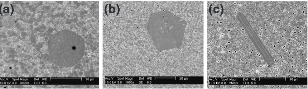
As shown earlier27)and in Fig. 1, all specimens with excess
TiO2showed abnormal grain growth. In the 0.1 Ti and 0.3 Ti
specimens, the abnormal grains had equiaxial shapes while in the 0.5 Ti specimens the abnormal grains were elongated parallel to the an [111] direction of their double twins. The matrix grains in all specimens, shown in Fig. 2 for the 0.3 Ti/ 24 h specimen as an example, grew very slowly. Between sintering for 1 and 24 h, they grew by only about 5%. Figure 2 shows typical morphologies of the matrix grains as observed by SEM at a low magnification after chemical etching. Some grain boundaries (indicated by black arrows) appeared to be straight and others (indicated by white arrows) appeared to have h&v or stepped shapes. Some appeared to be curved. The matrix grains with their low index zone axes nearly parallel to the beam direction were selected for TEM examination.
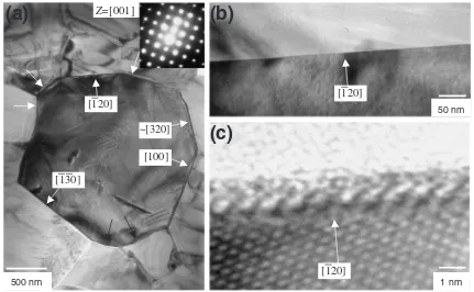
The grain boundaries of a grain with a [001] zone axis in the 0.1 Ti/10 h specimen is shown in Fig. 3(a). There are straight grain boundary segments that lie on (100) and other low index planes of the grain. The low index grain boundary that lies on (ijk) plane at one side will be designated as a (ijk) grain boundary in this report. An ð1120Þ grain boundary is shown at different magnifications to confirm its flat shape
(a)
(b)
(c)
Fig. 1 SEM microstructures of abnormal grain growth in (a) 0.1 Ti/8 h, (b) 0.3 Ti/24 h and (c) 0.5 Ti/10 h specimens.
[image:2.595.53.547.72.215.2] [image:2.595.312.542.263.447.2]even at fine scales. There were other boundary segments (indicated by white arrows) that also appeared to be straight and it is possible that they lay on the low index planes of the other surrounding grains. These flat low index grain boundaries are likely to be singular corresponding to the cusps in the polar plots of the grain boundary energy against the boundary normal (the grain boundary Wulff plot). As pointed out earlier, these grains were growing very slowly and the entire segments of theð1120Þ, (100) andð11330Þgrain boundaries in Fig. 3(a) were straight between the triple points. If these grain boundaries were rough, they would have been curved because of the size difference between the
grains. Some grain boundaries (indicated by black arrows) shown in Fig. 3(a) appeared to be curved, but they may have h&v or stepped structures at fine scales.
Figure 4 shows a grain boundary in the same specimen with a flat (101) segment that became curved near the triple junction. The high resolution image of the insert shows that the curved segment consists of (101) terraces and small steps. This observation shows that the macroscopic deviation from the low index planes produced by the constraints of the triple junctions can be accommodated by grain boundary steps. It is also possible that this curved segment is migrating by the lateral movement of the steps. Such a structure demonstrates Z=[001]
[100]
[130]
~[320] [120]
500 nm 1 nm
[120]
50 nm
(a)
(b)
(c)
[120]
Fig. 3 TEM microstructure of (a) a grain and its grain boundaries in 0.1 Ti/10 h specimen, (b) theð1120Þgrain boundary at a higher magnification and (c) its high resolution image.
1 nm 40 nm
[101] [111]
Z=[111]
[121]
[image:3.595.82.513.72.338.2] [image:3.595.91.504.396.602.2]that the singular low index grain boundary can migrate by lateral movement of grain boundary steps produced either by two dimensional nucleation as proposed by Babcock and Balluffi28)or by such defects as dislocations.29,30)In the 0.1
Ti/10 h specimen, five grains with low index zones were examined by TEM and all of them showed at least one boundary lying on the low index planes of the grains. The {011} grain boundaries and segments were most frequently observed and {001}, {012} and {013} grain boundaries were also observed.
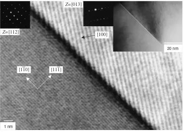
The specimens with 0.3 mol% Ti also showed a similar variety of singular grain boundaries. Figure 5 shows a grain at the center withð1111Þgrain boundary segments separated by a
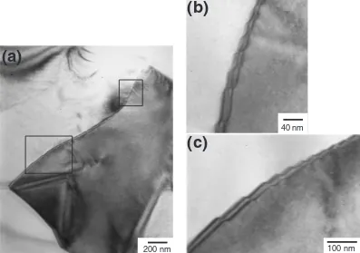
ð3111Þstep, a h&v grain boundary withð11222Þandð33111Þplanes and a ð2111Þ boundary segment. There were other flat boundaries and they may have been parallel to the low index planes of the other surrounding grains. Another ð1111Þgrain boundary that is parallel to anð1111Þplane on one side and a high index plane on the other is shown in Fig. 6. Figure 7 shows a grain boundary with a h&v shape of which both segments had low index planes on one side. A h&v grain boundary with ð0111Þandð1111Þsegments was shown in our previous report.26)Figure 8 shows an example of a boundary
with fine h&v structures that would have looked curved at lower magnifications. A grain boundary with small (210) terraces and (120) steps was also shown earlier.26) (Grain boundaries with terrace and step structures can also be considered as h&v boundaries at fine scales.). Figure 9 shows a triple junction indicated by an arrow where three apparently flat boundary segments intersect. Because these are likely to be singular, their equilibrium at the triple junction strongly depends on the boundary torque effect, which may be described by using the capillarity vectors of Hoffmann and Cahn.31,32)In the 0.3 Ti/10 h and 0.3 Ti/48 h specimens, 12
grains with low index zones were examined by TEM and all of them showed at least one boundary lying on the low index planes of the grains. The {111}, {001}, {012} and {011} grain boundaries were frequently observed, but there were also {112}, {113}, {114} and {122} grain boundaries as shown in these micrographs. Some grain boundary segments between the large abnormal grains and the matrix grains were parallel to the low index planes of the abnormal grains as shown in Fig. 10. This (120) boundary shows a periodic structure similar to that observed in a Ti-doped BaTiO3 by
Yamamoto, et al.10,11) They attributed such a boundary
Z=
[011]
[122]
[311]
[311]
[211]
[111]
[111]
[311]
[122]
200 nm
Fig. 5 TEM microstructure of a grain and its grain boundaries in 0.3 Ti/ 10 h specimen.
[111] [110]
[100] Z=[112]
Z=[013]
20 nm
1 nm
[image:4.595.320.533.71.290.2] [image:4.595.113.485.504.771.2]structure to a segregated TiO2 layer at the boundary on the
basis of electron energy loss spectroscopy.10,11)
In the 0.5 Ti/10 h specimen, 12 grains with low index zones were examined by TEM and all of them showed at least one boundary lying on the low index planes of the grains. The {111} grain boundaries were most frequently observed and the {011}, {012}, {001} and {013} grain boundaries were also frequently observed as shown in Figs. 11, 12 and 13.
There were very few boundary segments that appeared to be curved even at macroscopic scales indicating that the boundaries were strongly singular. Figure 12 shows a grain at the center with ð1111Þ boundary segments. This ð1111Þ
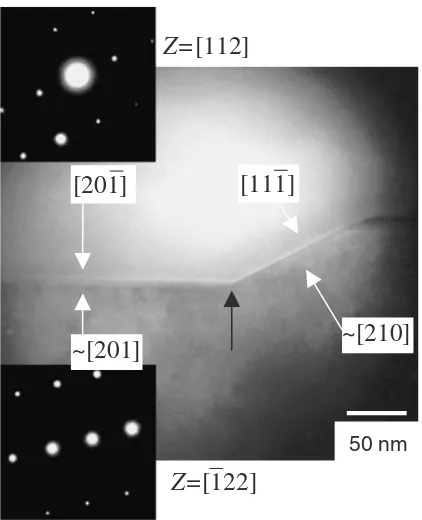
boundary also shows a periodic structure which may be produced by Ti segregation. Figure 13 shows a (201) grain boundary intersecting an (111) boundary with a sharp kink (indicated by an arrow). There were a small fraction of grain
Z=
[110]
250 nm 100 nm
[114]
[001]
[114]
[001]
[114]
[001]
(a)
(b)
Fig. 7 TEM microstructure of (a) a grain and its grain boundaries in 0.3 Ti/10 h specimen and (b) the rectangular region of (a) at a higher magnification.
(a)
(b)
(c)
100 nm 40 nm
200 nm
[image:5.595.98.499.71.311.2] [image:5.595.99.496.368.647.2]boundaries that were not parallel to any low index plane on either side as shown in the insert of Fig. 14. However, the high resolution image in Fig. 14 shows a grain boundary with fine (100) terraces and steps.
As pointed out earlier in this report, these low index grain boundaries are likely to be singular and hence thermody-namically stable. They appear so frequently in these speci-mens because they form with a variety of low index planes on one side. Because the other side can be any high index plane, these singular boundaries and segments form with any misorientation angle between the grain pairs. At the sintering temperature of 1250C, these low index grain boundaries
appeared only when there was excess Ti, but it is possible that even without excess Ti, such singular boundaries can form at low temperatures as in other pure materials such as Au,8)
100 nm
Fig. 9 TEM microstructure of three grain boundaries intersecting at a triple junction (indicated by an arrow) in 0.3 Ti/10 h specimen.
1 nm
Abnormal Grain
Matrix Grain
Z=
[001]
40 nm[120]
[image:6.595.49.290.74.217.2][120]
Fig. 10 High resolution image of the circled segment of a grain boundary between an abnormal grain and a matrix grain in 0.3 Ti/10 h specimen shown in the insert.
Z=
[122]
[011]
[210]
[201]
[image:6.595.72.525.280.482.2]200 nm
Fig. 11 TEM microstructure of a grain and its grain boundaries in 0.5 Ti/ 10 h specimen.
200 nm
(a)
(b)
(c)
1 nm
Z=[110]
[111]
[111]
50 nm
[image:6.595.306.548.531.746.2] [image:6.595.67.270.552.758.2]Mo9)and alumina.3)Such low index singular grain bounda-ries cannot be explained by the coincidence site lattice model or any present theory of grain boundary structure. While the roughening effect of temperature is qualitatively predictable, the effect of additives is not presently understood. Because the singular boundaries migrate by the lateral growth of steps that are either nucleated or produced by such defects as screw dislocations, as indicated by the step structures observed in these specimens, the matrix grains grow very slowly after sintering for 1 h while only a few grains grow abnormally to large sizes. As the excess Ti content increases from 0.1 to 0.5 mol%, the boundaries appear to become more strongly singular and hence the matrix grains grow more slowly as reported earlier.27)In the 0.5 Ti specimen, the {111} grain
boundaries appeared to be most strongly singular (with the largest step free energy) and the abnormal grains also had the largest {111} boundary area. It is likely that the nearly polyhedral shapes of the abnormal grains in the 0.1 and 0.3 Ti specimens also reflect the most strongly singular boundaries.
4. Conclusions
Previous works showed only selected examples of low index grain boundaries in Ti-excess BaTiO3. The extensive
examination of randomly selected grain boundaries in this work showed that the majority of the grain boundaries in Ti-excess BaTiO3 have various low indices on one side with
many different shapes. The dominant low index planes also vary with the excess Ti content. The {111} grain boundaries in particular appear to be the most strongly singular in the 0.5 Ti specimen while they hardly appear in the 0.1 Ti specimen. The low index singular grain boundaries also observed in many other materials cannot be satisfactorily explained by present theories of grain boundary structure. The stagnant
growth of the matrix grains during abnormal growth of a few grains is consistent with the step migration mechanism of the singular grain boundaries. A small fraction of the grain boundaries that were curved at low magnifications or did not exactly coincide with any low index plane may be rough for their particular misorientation at this sintering temperature or may have become kinetically rough because of their relatively high velocity.
Acknowledgment
This work was supported by the Korea Ministry of Education through the Brain Korea 21 project.
REFERENCES
1) J. C. Heyraud and J. J. Me`tois: J. Cryst. Growth84(1987) 503–508. 2) T. Ohachi and I. Taniguchi: J. Cryst. Grwoth65(1983) 84–88. 3) M. J. Kim and D. Y. Yoon: J. Am. Ceram. Soc.86(2003) 630–633. 4) R. Warren: J. Inst. Met.100(1972) 176–181.
5) S. Sarian and H. W. Weart: Trans. Metall. Soc. AIME233(1965) 1990–1994.
6) Y. K. Cho, D. Y. Yoon and B.-K. Kim: J. Am. Ceram. Soc.87(2004) 443–448.
7) Y. J. Park, N. M. Hwang and D. Y. Yoon: Metall. Mater. Trans.27A (1996) 2809–2819.
8) H. Ichinose and Y. Ishida: J. PhysiqueC4(1985) 39–49. 9) J.-M. Penisson: J. PhysiqueC5(1988) 87–97.
10) T. Yamamoto, Y. Ikuhara, K. Hayashi and T. Sakuma: J. Mater. Res.13 (1998) 3449–3452.
~[201]
~[210]
Z=
[112]
Z=
[122]
[111]
[201]
[image:7.595.64.275.70.330.2]50 nm
Fig. 13 TEM microstructure of a grain boundary in 0.5 Ti/10 h specimen.
1 nm
[011]
[100]
Z=
[011]
[100]
[image:7.595.317.533.72.395.2]40 nm
11) T. Yamamoto, Y. Ikuhara, K. Hayashi and T. Sakuma: Mater. Sci. Forum294–296(1999) 247–250.
12) S. B. Lee, S.-Y. Choi and D. Y. Yoon: Z. Metallkd.94(2003) 193–199. 13) S. B. Lee, W. Sigle and M. Ru¨hle: Acta Mater.50(2002) 2151–2162. 14) S.-Y. Chung and S.-J. L. Kang: Acta Mater.51(2003) 2345–2354. 15) M. A. Gu¨lgu¨n, V. Putlayev and M. Ru¨hle: J. Am. Ceram. Soc.82
(1999) 1849–1856.
16) C. W. Park, D. Y. Yoon, J. E. Blendell and C. A. Handwerker: J. Am. Ceram. Soc.86(2003) 603–611.
17) S. B. Lee, N. M. Hwang, D. Y. Yoon and M. F. Henry: Metall. Mater. Trans.31A(2000) 985–994.
18) J. S. Choi and D. Y. Yoon: ISIJ Int.41(2001) 478–483.
19) Y. K. Cho, D. Y. Yoon and M. F. Henry: Metall. Mater. Trans.32A (2001) 3077–3090.
20) J. S. Choi and D. Y. Yoon: ISIJ Int.43(2003) 245–250.
21) D. M. Saylor, B. S. El-Dasher, Y. Pang, H. M. Miller, P. Wynblatt, A. D. Rollett and G. S. Rohrer: J. Am. Ceram. Soc.87(2004) 724–726.
22) D. M. Saylor, A. Morawiec and G. S. Rohrer: Acta Mater.51(2003) 3675–3686.
23) D. M. Saylor, A. Morawiec and G. S. Rohrer: Acta Mater.51(2003) 3663–3674.
24) D. M. Saylor, B. S. El-Dasher, T. Sano and G. S. Rohrer: J. Am. Ceram. Soc.,87(2004) 670–676.
25) D. M. Saylor, B. L. Adams and G. S. Rohrer: Metall. Mater. Trans. in press.
26) Y. K. Cho and D. Y. Yoon: J. Am. Ceram. Soc.87(2004) 438–442. 27) Y. K. Cho, S.-J. L. Kang and D. Y. Yoon: J. Am. Ceram. Soc.87(2004)
119–124.